Wrist
Robert SD Campbell
John H. Harris Jr.
INTRODUCTION
Radiography remains the primary investigation for trauma of the wrist. The requirement for implementing secondary imaging modalities is dictated by clinical and x-ray findings. Computed tomography (CT) is commonly used for surgical planning of complex fractures, detecting occult fractures, and assessment of fracture union. Magnetic resonance imaging (MRI) is useful for detecting occult fractures and assessment of ligament injuries. Both CT and MRI may be combined with arthrography to improve diagnostic accuracy of ligament injury.
This chapter concentrates on interpretation of radiographic examinations of wrist trauma. The indications for CT and MRI are discussed, but a full description of the complex soft tissue anatomy and pathology is beyond the scope of this text.
RADIOLOGIC TECHNIQUE
Radiographs
The wrist includes the articulations of the distal radius and ulna, the carpus, and the carpometacarpal joints. Attending physicians should indicate precisely the anatomic area for radiologic evaluation based on the clinical history and physical examination. It is important to acquire radiographs with appropriate positioning and beam centering in order to adequately evaluate wrist trauma. Properly positioned radiographs are essential for assessing carpal relationships. The distal radioulnar joint (DRUJ) and the radiocarpal, midcarpal, and carpometacarpal (CMC) joints should be fully included on all images.
A minimum of two radiographic projections (posteroanterior [PA] and lateral) should be acquired to fully evaluate injuries of the distal radius and ulna (Fig. 10.1). It is important to remember that injuries may affect more than one anatomic area. However, it is not necessary to routinely image both the wrist and the elbow in the instance of a suspected distal radial fracture if the physical examination of the elbow is negative and when the patient is alert, responsive, and communicative. It is also not necessary to routinely obtain radiographs of the normal contralateral wrist in children simply “for comparison.” Physicians interpreting skeletal radiographs of children and adolescents should be sufficiently familiar with the appearance of normal growing bones to be able to determine normality.
The routine radiographic study of the carpus should include at least a frontal, lateral, and a PA oblique projection (Fig. 10.2A-C).1 The PA oblique is obtained by elevating the radial border of the wrist by 30 degrees. An additional PA in ulnar deviation, the scaphoid (navicular) view, should be obtained in all patients with pain in the anatomical snuffbox to optimally demonstrate the waist of scaphoid. The scaphoid view is obtained with the hand in pronation and in maximum possible ulnar deviation. The central x-ray beam is centered over
the anatomic “snuffbox” and angled approximately 10 degrees in both an ulnar and proximal direction (Fig. 10.3). The radial surface of the scaphoid is seen in greater detail and in different perspective than in the PA projection. The normal dorsal ridge appears as a localized irregularity of the radial aspect of its cortex and should not be confused as a cortical buckling or incomplete fracture. The scaphoid view is not required in infants and very young children because scaphoid fractures are rare in this age group and the scaphoid does not ossify until 6 years of age.
the anatomic “snuffbox” and angled approximately 10 degrees in both an ulnar and proximal direction (Fig. 10.3). The radial surface of the scaphoid is seen in greater detail and in different perspective than in the PA projection. The normal dorsal ridge appears as a localized irregularity of the radial aspect of its cortex and should not be confused as a cortical buckling or incomplete fracture. The scaphoid view is not required in infants and very young children because scaphoid fractures are rare in this age group and the scaphoid does not ossify until 6 years of age.
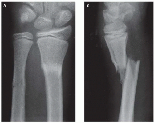 Figure 10.1. The distal radial and ulnar fractures are obvious in the frontal projection (A), but the marked displacement can only be appreciated in the lateral radiograph (B). |
Other radiographic projections have largely been abandoned in favor of CT imaging for acute trauma (Fig. 10.4). Multiple projections may be indicated for suspected carpal instability.
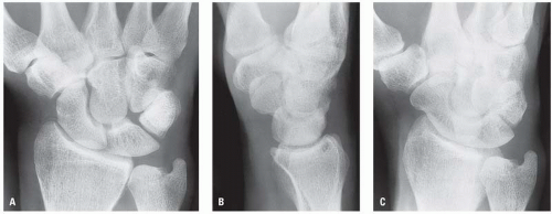 Figure 10.2. Normal adult wrist in frontal (A), lateral (B), and PA oblique projections (C). |
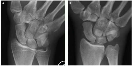 Figure 10.3. Additional radiographic projections for suspected scaphoid fracture include either a PA in ulnar deviation (A) or a PA with cranial and ulnar beam angulation (B). Both views show the long axis of the scaphoid in profile. |
Computed Tomography
High-resolution multiplanar reconstructed (MPR) images are obtained with multidetector computed tomography (MDCT), which provide specific information about fracture morphology in complex wrist fractures that assist surgical planning.2 Up to 30% of fractures are occult on plain radiographs, and MDCT has been shown to identify fractures with up to 100% sensitivity.3 This includes not only occult scaphoid fractures but also fractures of the lunate, triquetrum, capitate, and hamate, which are often poorly visualized or easily missed on radiographs.4 Caution is advised in interpreting radiographs of patients with marked osteopenia because fracture lines may be subtle.
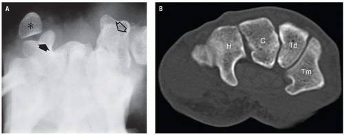 Figure 10.4. Carpal tunnel view demonstrating the pisiform (asterisk), the hook of the hamate (closed arrow), and the scaphoid bone (open arrow) (A). An axial CT image demonstrates more detail of the morphology and articulation of the carpal bones (B). H, hamate; C, capitate; Td, trapezoid; Tm, trapezium. |
CT of the wrist is performed with the patient prone and the arm outstretched above the head within the bore of the CT (the “superman” position). This may not be achievable in some trauma patients, in which case the patient is placed supine with the hand on the abdomen or by the patient’s side. However, image quality is compromised by beam-hardening effects. Alternatively, it is possible to sit the patient on a chair on the opposite side of the CT gantry with the shoulder abducted and the wrist positioned within the bore (Fig. 10.5).
Thin section volumetric scanning of the wrist (≤1 mm) is performed with a small field of view using bone algorithms that enhance bony detail. MPR images are acquired in the coronal, sagittal, and axial plane. Non-orthogonal MPR imaging in the oblique sagittal plane provides optimal visualization of the scaphoid (Fig. 10.6), which improves diagnostic accuracy and delineation of fracture patterns. The benefits of 3D MPRs of the wrist for surgical planning have not been proven.
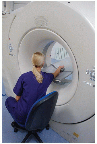 Figure 10.5. CT examinations of the wrist can be performed with the patient seated behind the gantry. This is a useful alternative to the supine position with the arm by the side to avoid beam-hardening artifact. |
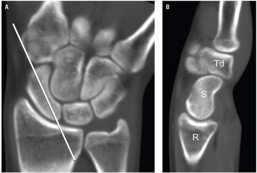 Figure 10.6. A coronal MPR CT image of the wrist (A) demonstrating the plane for obtaining an oblique sagittal long axis view of the scaphoid (B). R, radius; S, scaphoid; Td, trapezoid. |
Magnetic Resonance Imaging
MRI is indicated for evaluation of ligamentous injury and carpal instability. It may be used as an alternative to CT for early detection of occult trauma, especially in the context of scaphoid fractures.5, 6 Patient positioning is important for wrist imaging because of several potential problems. Movement artifacts may occur if the patient experiences pain or discomfort when the arm is placed above the head. With the arm by the side, the wrist lies in the periphery of the magnetic field, and field inhomogeneities may degrade image quality. Placing the hand on the abdomen results in breathing movement artifact. Phased-array wrist coils or knee coils with a 6 to 8 cm field of view provide the best image quality (Fig. 10.7). MRI of the wrist can be performed in a plaster cast, but this will limit coil selection.
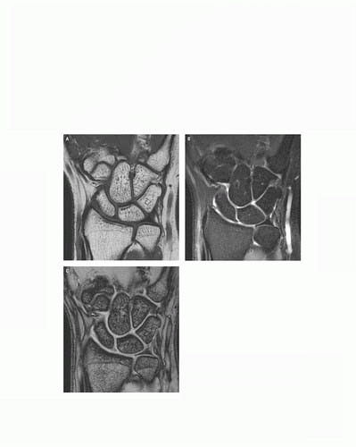 Figure 10.7. High-resolution MR images obtained on a 1.5T system with four channel wrist coil and an 8 × 8 cm field of view. The combination of a T1W sequence (A), a T2W fat saturation sequence (B) and T2* gradient echo sequence (C) provides excellent detail of bone, articular cartilage, fibrocartilage, and ligament anatomy. |
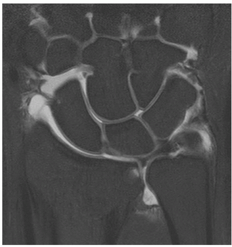 Figure 10.8. T1W fat saturation images are used to supplement other pulse sequences for MR arthrography. There is good delineation of articular cartilage in joints filled with dilute Gadolinium. |
Standard protocols for the wrist include T1W and fluid sensitive sequences such as T2W fat saturation or STIR sequences for optimal visualization of marrow edema associated with fractures and soft tissue edema in acute ligamentous injuries. A variety of gradient echo sequences can be used for cartilage imaging and delineation of small, thin ligaments. Images are obtained in coronal, sagittal, and axial planes.
Magnetic resonance (MR) (or CT) arthrography may be preferred for demonstration of the carpal ligaments and triangular fibro cartilage (TFC) in nonacute cases. Arthrography is usually performed under fluoroscopic guidance. A dilute solution of gadolinium is mixed with iodinated contrast in order to obtain images during joint injection and to identify sites of abnormal communication between joint compartments.7 T1W fat saturation sequences are used to supplement the other standard sequences in conventional MR wrist imaging (Fig. 10.8).
RADIOLOGIC ANATOMY
The radius and ulna articulate with the proximal carpal row through the radiocarpal and ulnocarpal joint. The ulnocarpal joint also contains the TFC complex. The distal radius is divided into radial and ulnar facets that articulate with the scaphoid and lunate, respectively. The articular surfaces of the ulna and radius should be approximate (Fig. 10.9), although the length of the ulna can vary in some individuals, being either longer (ulnar plus variance) or shorter (ulnar minus variance). In addition, there is an increase in ulnar plus variance in full pronation and on fist clenching, compared to forearm supination. Radiographic analysis should include an evaluation of the radial height, radial inclination, and volar tilt (Fig. 10.10). Other measurements may include the radiocarpal angle and the carpal height ratio.
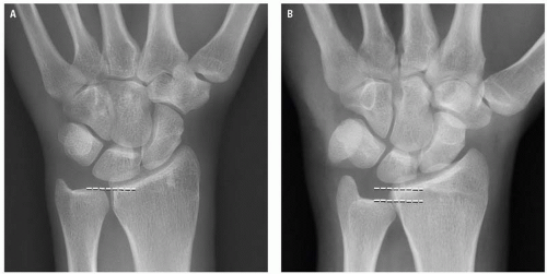 Figure 10.9. Radiographs demonstrating normal ulnar variance (A) and ulnar minus variance (B). |
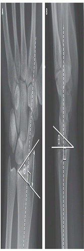 Figure 10.10. Normal wrist measurements. The radial inclination angle is subtended between a line drawn perpendicular to the long axis of the radius and a line drawn along the length of the articular surface of the radius (A). The normal radial inclination angle θ is approximately 22 degrees. The radial height (double arrow) is approximately 11 degrees. The degree of normal volar radial tilt measured on a lateral radiograph is approximately 11 degrees (B). |
The eight carpal bones are divided into two horizontal rows. The proximal row consists of the scaphoid, lunate, and triquetrum. The pisiform is a sesamoid bone formed within the tendon of the flexor carpi ulnaris and articulates with the volar aspect of the triquetrum. The proximal row of carpal bones forms the intercalated segment of the wrist. The main function of these bones is to coordinate the complex range of movements that occurs between the distal radius and the distal carpal row, thereby maintaining the stability of the wrist joint. The distal carpal row consists of the trapezium, trapezoid, capitate, and hamate. They have a more rigid configuration with less movement than the proximal row.
On a PA radiograph, the articular surfaces of the proximal and distal carpal row form continuous arcs (the arcs of Gilula) (Fig. 10.11).8 There should be no interruption of the congruity of the arcs. The width of the scapholunate space must be measured at, or distal to, its midpoint and should be equivalent to the other intercarpal joints and measure <3 mm.
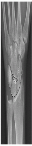 Figure 10.11. The three arcs of Gilula comprise the proximal and distal articular surfaces of the proximal carpal row and the proximal articular surfaces of the distal carpal row (broken lines). These should be continuous smooth arcs with no steps between joints. |
On a well-positioned lateral radiograph of a normal adult wrist, the axis of the distal radius, lunate, and capitate should be linear, with congruence between the articular surfaces (Fig. 10.12). The long axis of the lunate and capitate should align with an angle of 0 degree ±15 degrees. The scapholunate angle is important for assessment of carpal instability. This is the angle subtended between the long axis of the scaphoid bone and the lunate, and it should normally measure between 30 degrees and 60 degrees (Fig. 10.13).9
The carpometacarpal joints are arthrodial (gliding) diarthroses except for the fifth, which is a modified saddle joint. All metacarpal bones articulate with the distal row of carpal bones and with each adjacent metacarpal, which results in great mechanical stability. The third CMC articulation provides very little movement and is a prime stabilizing factor of the carpometacarpal joint. Greater flexibility and mobility are present at the fourth and fifth carpometacarpal joints.
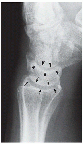 Figure 10.12. Lateral radiograph of the normal wrist. The contiguous concave surface of the distal radius and the proximal convex surface of the lunate (arrows) are normally congruous, as are the contiguous concave distal articulating surface of the lunate and the proximal convex surface of the capitate (arrowheads). Normally, a line drawn to the midsagittal plane of the carpus should bisect both the lunate and capitate bones. In this case, the capitate is rotated slightly posterior to this line. |
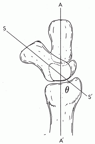 Figure 10.13. Schematic representation of the normal alignment of the distal radius, lunate, scaphoid, and capitate in lateral projection. The axis of the distal radius, lunate, and capitate should be linear. The long axis of the scaphoid bone (S-S’) should normally be at an angle of 30 to 60 degrees to the linear axis (A-A’). The scapholunate angle is indicated by θ. (From Mirvis SE, Young JWR, eds. Imaging in Trauma and Critical Care. Baltimore, MD: Lippincott Williams & Wilkins, 1992:470. Used with permission.) |
The ligaments of the wrist are complex and are interconnected in their actions. They are divided into the intrinsic and extrinsic ligaments.9 The intrinsic ligaments (scapholunate and lunotriquetral ligaments) stabilize the intercalated segments of the proximal carpal row. Each intrinsic ligament consists of three parts. There are relatively strong volar and dorsal components, with a thinner central membranous portion (Fig. 10.14). The extrinsic ligaments of the wrist are situated over both the volar and dorsal aspects of the wrist and help stabilize movement between rows (radiocarpal joint and midcarpal joint). They include the volar radioscaphocapitate and radiolunate-triquetral ligaments and the dorsal radioscaphoid, radiolunate, and radiotriquetral ligaments.10
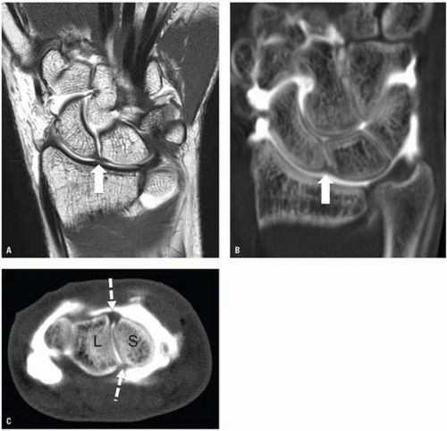 Figure 10.14. T1W image of an MR arthrogram demonstrating the normal scapholunate ligament (arrow). A three joint compartment injection has been performed, and both aspects of the ligament are outlined by contrast (A). A CT image from the same patient also clearly demonstrates the scapholunate ligament (arrow) (B). The axial CT image (C) demonstrates the dorsal and volar components of the ligament (broken arrows). L, lunate; S, scaphoid. |
RADIOLOGIC MANIFESTATIONS OF TRAUMA
Distal Radius and Ulna Fractures
Distal radial fractures are the most common fractures around the wrist. The most common mechanism of injury is a fall on the outstretched hand with the hand and wrist in dorsiflexion, which results in a variety of injuries depending on the patient’s age. This may be as a result of either a high-energy injury in young patients or low-energy injury in the older osteoporotic individual.
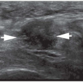
Localized soft tissue swelling about the wrist may be the most obvious radiographic finding in instances of subtle skeletal injury (Fig. 10.15). The pronator quadratus muscle is a quadrangular muscle that passes transversely from the distal radius to the distal ulna. Superficially, it is covered with a layer of loose fatty areolar tissue, which is visible as a linear area of low density on the lateral radiograph of the wrist (Fig. 10.16A). Hemorrhage beneath the pronator quadratus muscle causes muscle bulging, which either displaces or obliterates the pronator fat stripe (Fig. 10.16B).11 This is a useful sign in the presence of subtle injuries of the distal third of the radius or ulna.
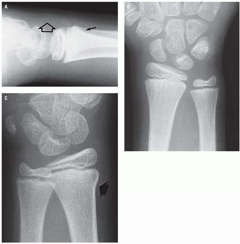 Figure 10.15. Soft tissue swelling over the dorsum of the wrist (open arrow) on the lateral projection (A) is the most prominent sign of the subtle cortical buckling fracture of the distal radius (solid arrow), which was not visible on the PA radiograph (B) but was confirmed (arrow) on the oblique projection (C). |
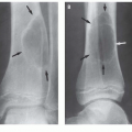
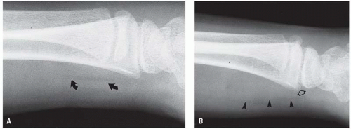 Figure 10.16. Normal pronator fat stripe (black arrows) (A). The abnormal pronator quadratus muscle sign (arrowheads) on the lateral radiograph (B) represents the hematoma associated with the minimally displaced distal radial metaphyseal fracture (open arrow). |
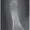
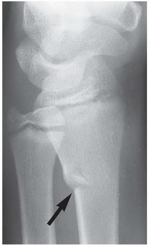 Figure 10.17. Cortical buckling or greenstick fracture (arrow) of the dorsal cortex of the distal radius. |
Distal Radial Fractures in Children
In the young child, a fall on the outstretched hand may produce a greenstick (cortical buckling) fracture of the distal radius (Fig. 10.17); a “torus” fracture, which is a circumferential impacted cortical buckling fracture (Fig. 10.18); a complete fracture of the distal third of one forearm bone with a cortical buckling fracture of the other (Fig. 10.19); or one of the Salter-Harris injuries, primarily of the distal radial physis. Colles fractures are uncommon in children (Fig. 10.20).
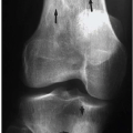
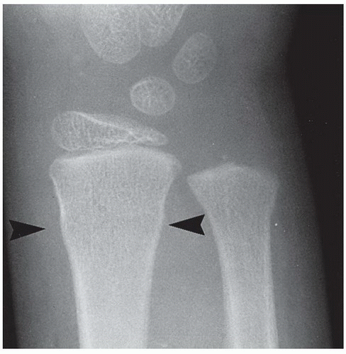 Figure 10.18. Torus fracture (arrowheads) of the distal radial metaphysis. The fracture is indicated by the very short, focal convexities of the distal cortex. No fracture line or trabecular impaction is visible. |
 Figure 10.19. Torus fracture (arrowheads) of the distal radius with a minimally displaced complete fracture of the distal ulna (arrow). |
The Salter-Harris physeal injuries of the wrist are usually of the type I or type II variety caused by the shearing or twisting mechanism of injury associated with falls on the outstretched hand. The type I injury may be very subtle (Fig. 10.21) or obvious (Fig. 10.22) as may be the type II injury (Figs. 10.23 and 10.24).
The distal radial physis fuses in the mid-to-late teens. The physeal “scar” may simulate an incomplete or minimally displaced impacted fracture (Fig. 10.25). The absence of soft tissue swelling, the smooth sclerotic margins, and the typical location should aid differentiation from a genuine fracture.
Distal Radial Fractures in Adults
A variety of different fractures of the distal radius occur dependent on the mechanism of injury.1 They may be extraarticular or intra-articular. Historically, many of these fractures have been given eponymous titles, some of which remain in common usage.
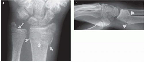 Figure 10.20. Extra-articular (Colles) distal radial fracture (arrows) in PA (A) and lateral (B) projections associated with a fracture of the base of the ulnar styloid (curved arrow, A). |
 Figure 10.21. Subtle Salter-Harris I physeal injury. On the PA radiograph (A), the distal radial physis is minimally displaced (open arrow), and a tiny metaphyseal fragment (arrow) is present along the radial aspect of the physis. The strict definition of the Salter-Harris I injury does not include a fracture. However, tiny fragments of this size in or adjacent to the physis (which may arise from either the epiphysis or metaphysis) do not fulfill the criteria of a Salter-Harris II injury. The lateral radiograph (B) shows soft tissue swelling of the dorsum of the wrist (asterisk), an absent pronator quadratus muscle shadow (open arrow), and dorsal displacement of the distal radial physis (arrow). |
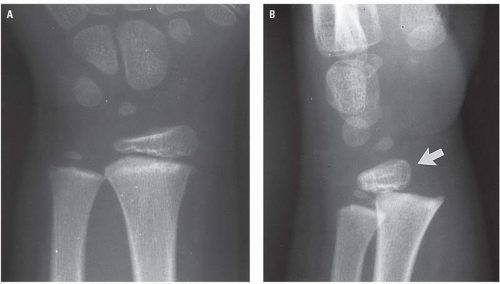 Figure 10.22. Displaced Salter-Harris type I distal radial physeal injury. On the PA projection (A), the relationship of the distal radial epiphysis to its metaphysis appears normal. On lateral projection (B), however, dorsal displacement of the distal radial epiphysis (arrow) is clearly evident. |
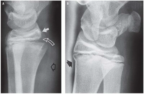 Figure 10.23. Volar bulging of the fascial plane (open arrow) covering the abnormally thickened pronator quadratus muscle shadow on the lateral projection (A) is the most prominent radiographic sign of the very subtle Salter- Harris II injury. The distal radial epiphysis (arrow) is slightly, but definitely, dorsally displaced and the volar aspect of the physis is wide (curved arrow) on the lateral (A) projection. The metaphyseal component of the type II injury (arrow) is evident on the oblique radiograph (B). |
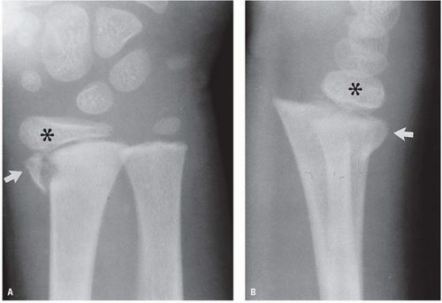 Figure 10.24. Salter-Harris type II distal radial physeal injury. The distal fragment of the Salter-Harris II consists of the distal radial epiphysis (asterisk) and a triangular metaphyseal fragment (arrow) adherent to the epiphysis through the intact physis. The distal fragment is radially displaced on the PA view (A) and dorsally displaced on the lateral (B) radiograph. |
Colles Fracture
The Colles fracture is the most common distal radial fracture. It is a transverse fracture of the distal metaphysis with dorsal angulation and dorsal and proximal displacement of the distal fragment (Figs. 10.20 and 10.26). The classic “dinner fork” deformity is typically evident on lateral radiographs (Fig. 10.26B). A Colles fracture is frequently associated with an avulsion of the base of the ulnar styloid process caused by the intact ulnar collateral ligament (Fig. 10.27). Intra- articular fracture extension is a common occurrence (Fig. 10.28). Impacted or depressed articular fragments are sometimes referred to as “die-punch” fractures.
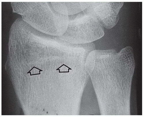 Figure 10.25. Normal appearance of the scar of the distal radial physis (open arrows). It appears as a thin sclerotic line and should not be mistaken for a fracture. |
Smith Fracture
The Smith fracture is the reverse of the Colles fracture, but it occurs less commonly. It typically results from a fall on the flexed wrist. The distal radial fragment, together with the carpus and bones of the hand, is displaced in a volar direction and rotated proximally (Figs. 10.29 and 10.30). Smith fractures may also be intra-articular or extraarticular. They are uncommon in children.
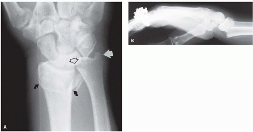 Figure 10.26. A typical Colles fracture as originally described. The PA view (A) shows the intact ulnar styloid process (arrow), radiocarpal diastasis (open arrow), and the transverse distal radial fracture (curved arrows) without intra-articular extension. In the lateral projection (B), dorsal and proximal displacement of the distal radial fragment, together with the bones of the wrist and hand, has resulted in the typical dinner fork deformity. |
 Figure 10.27. Colles fracture with characteristic distal radial fracture line and displacement of the distal radial fragment (A and B). Displacement of the ulnar styloid fragment (arrow) suggests avulsion by an intact triangular fibrocartilage. Dorsal displacement of the distal radial fragment causes disruption of the distal radioulnar joint (open arrows). |
 Figure 10.28. Severely comminuted intra-articular distal radial fracture. The widely separated, comminuted distal radial fragments (arrows) are more evident on the PA view (B) than on the lateral (A) projection. On the lateral view (A), the distal ulna (arrowheads) largely obscures one of the distal radial fragments (open arrows). |
Barton Fracture
The Barton fracture differs from the Colles and the Smith fracture in that the distal radial fracture line is obliquely, rather than transversely, oriented and is intra-articular. The oblique fracture line runs primarily in the coronal plane and may involve the either the dorsal aspect of the distal radius (Fig. 10.31) or the volar aspect (Fig. 10.32). The volar pattern fracture is most common. The fragment size may vary. The radiocarpal separation may be minimal, or there may be a complete dislocation (Fig. 10.33).
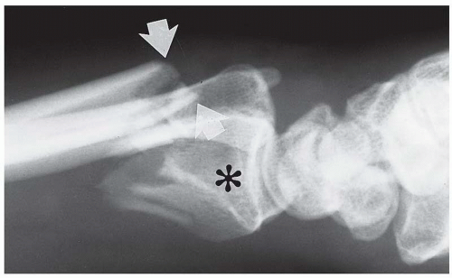 Figure 10.29. Smith fracture characterized by a transverse fracture (arrows) of the distal radius with volar and proximal displacement of the distal radial fragment (asterisk). |
Other Fracture Patterns
Related posts:
Stay updated, free articles. Join our Telegram channel

Full access? Get Clinical Tree


