Fundamentals of Ultrasound
Kenneth Kelley
John S. Rose
Aaron E. Bair
INTRODUCTION
The clinical application of ultrasound relies on a foundational understanding of the physical properties of sound waves. The better one’s understanding of the principles governing sound transmission, the more able one will be to both acquire and interpret meaningful images. This chapter will review the basics of ultrasound transmission and image acquisition, describe common artifacts, and give an overview of basic ultrasound equipment.
BASIC DEFINITIONS AND PRINCIPLES
Properties of Mechanical Waves
The practical application of ultrasound is improved by understanding some basic physical principles and definitions. Ultrasound is a form of sound energy that behaves like and follows the properties of a longitudinal mechanical wave. The “wave” is the propagation of an acoustical variable (e.g., pressure) over time; the most basic repeatable unit of a wave defines a cycle. Frequency is defined as the number of cycles per second and is measured in megahertz (MHz). Medical applications for ultrasound typically use transducers with a frequency range of 2 to 12 MHz. Wavelength is defined as the length over which one cycle occurs. A high-frequency wave has a short cycle and a short wavelength; a lower-frequency wave travels more distance per cycle, and thus has a longer wavelength. This inverse relationship between frequency and wavelength impacts the frequency chosen to image tissues at different depths. Transducers are designed to generate sound waves of different frequencies. General-purpose transducers for abdominal scans typically use 3- to 5-MHz frequencies (and long wavelengths) to penetrate and image objects between 5 and 15 cm deep. In contrast, transducers for vascular and soft tissue use frequencies between 10 and 12 MHz (higher frequencies and thus shorter wavelengths) to optimally image objects between 2 and 4 cm deep.
The manner in which ultrasound interacts with tissue is largely determined by impedance. Impedance is an inherent characteristic of each tissue, defined as the product of propagation velocity and density. In turn, propagation velocity is defined as the speed with which a wave moves and is determined by the density and stiffness of the medium traveled through (or tissue). As ultrasound interacts with tissue, its behavior is largely determined by the intrinsic impedance of each tissue, and impedance changes at tissue interfaces. Each of these definitions has significance when ultrasound interacts with tissue.
As sound waves travel through a medium, they cause molecules to vibrate. The molecules vibrate at a given frequency depending on the frequency of the sound. The sound wave then propagates through the medium (tissue) at that frequency. The frequency of these wavelengths determines how they penetrate tissue and affect image detail. The energy of a sound wave is affected by many factors. The spatial pulse length (SPL) is the basic unit of imaging. The SPL is a sound wave packet that is emitted from the transducer. Much like sonar, where the sound wave is sent out at a given frequency and then bounces off an object to locate it, diagnostic ultrasound can use sound waves to generate an anatomic picture. In essence, the sound waves “interrogate” the tissues to create an image. By adjusting various parameters of the sound wave and its production, the ultrasound wave can be used to gather information.
Sound waves are generated by piezoelectric elements in the probe. Piezoelectric elements are crystals that vibrate when alternating current is applied. Similarly, if ultrasonic waves hit these crystals, they vibrate and generate an electric current (Fig. 2.1). This characteristic enables them to act as both an emitter and receiver of sound waves and thereby function as a transducer. In medical ultrasound, piezoelectric crystals are placed in a sealed container, the “probe.” The probe houses the transducer and comes in contact with the patient.
Impedance
All mediums have an inherent impedance or resistance to the propagation of sound. As a sound wave travels through a medium of one impedance and crosses into a medium of another impedance, it encounters a change in impedance at the interface between the two media. Reflection of the sound occurs at this interface (Fig. 2.2). If the body had only one uniform density with tissues of similar or identical impedance, then no image could be generated because no reflection would occur. The amount of reflection is proportional to the difference in the acoustic impedance between the two media. The faces of ultrasound transducers are designed with material that has an impedance similar to that of epidermis to allow the signal to penetrate biological tissue. Ultrasound gel is used to prohibit air from interfering with the transmission of the signal. In general, tissues that interface with objects of high acoustic impedance, such as bone, reflect much (if not all) of the signal back to the transducer, generating a strong echogenic image. The fact that different tissues have different impedance allows detailed imaging by ultrasound.
Attenuation
As sound waves leave the transducer and propagate into biological tissue, they start to undergo a process of attenuation, the loss of amplitude and intensity. The frequency of the wave, the distance of travel (i.e., depth in tissue), as well as the angle of the ultrasound transducer will affect attenuation of sound waves. In general, high-frequency signals have a high attenuation coefficient. Thus, high-frequency waves undergo rapid attenuation; they have excellent resolution of shallow structures but limited penetration. Lower-frequency waves have less attenuation and penetrate deeper structures. Attenuation occurs through four processes: absorption, reflection, refraction, and scatter.
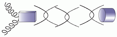 FIGURE 2.1. Piezoelectric Effect. Notice that if a current is applied to the crystal on the left, a signal is generated. As sound waves return and hit the crystal, it will vibrate and generate a current. |
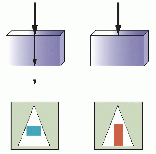 FIGURE 2.2. The illustration on the left demonstrates that as the sound waves hit an object, the impedance difference between the mediums causes a portion of the signal to return to the transducer and a portion to continue. The continuing signal is attenuated. The amount of reflected signal depends on the degree of impedance change encountered. In the illustration on the right, if the object is very dense, the entire signal is attenuated and there is acoustic silence or an anechoic signal on the monitor. The top images illustrate a sound wave striking an object. The bottom figures illustrate the image generated on the monitor. |
Absorption is the conversion of the sound wave to heat and is responsible for the majority of attenuation that takes place.
Reflection causes the signal to return to the transducer to generate an image.
Reflection occurs as a result of impedance mismatches between tissue layers. The angle of reflection is important in producing good ultrasound images. In order to ensure that the majority of sound is reflected back to the transducer and not reflected away at an angle, it is important that the transducer is perpendicular to the structure of interest (Fig. 2.3).
There are two types of reflectors: specular and diffuse. Specular reflectors are smooth, well-defined structures that are larger than the incident sound wave. Examples of specular
reflectors include bladder, diaphragm, and tendons. These structures appear hyperechoic, and they are well defined because they effectively reflect back the majority of the incident sound in a singular direction. Diffuse reflectors are usually irregular in shape, and the irregularities are of similar size to the incident sound waves, which cause reflection of the waves in multiple disorganized directions back to the transducer. This is also referred to as backscatter. Examples of diffuse reflectors are organs such as kidney, liver, and spleen.
reflectors include bladder, diaphragm, and tendons. These structures appear hyperechoic, and they are well defined because they effectively reflect back the majority of the incident sound in a singular direction. Diffuse reflectors are usually irregular in shape, and the irregularities are of similar size to the incident sound waves, which cause reflection of the waves in multiple disorganized directions back to the transducer. This is also referred to as backscatter. Examples of diffuse reflectors are organs such as kidney, liver, and spleen.
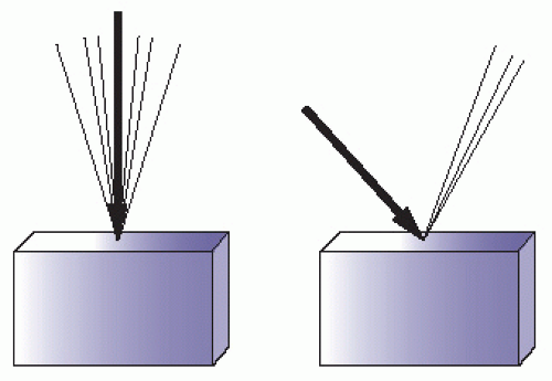 FIGURE 2.3. The figure on the left demonstrates good perpendicular scanning. The entire signal is returning to the transducer. The signal on the right is hitting the object of interest at an angle, causing poor signal return, resulting in a less sharp image. |
Refraction is the effective bending of sound waves as they travel at an oblique angle through two tissue layers with different speeds of propagation. Refraction is an inefficient use of the signal. Objects are optimally imaged when the incident beam strikes the object of interest perpendicular to it.
Scattering occurs when an incident sound wave hits an irregular surface that is similar to or smaller in size than the incident sound wave. Scattering causes chaotic reflection of sound in a multitude of directions with little useful reflection back to the transducer. Irregular, heterogeneous structures tend to create scatter. Air distorts and scatters ultrasound and prevents transmission to deeper structures (Fig. 2.4).
Resolution
Resolution refers to the ability of the sound waves to discriminate between two different objects and generate a separate image of each. There are two types of resolution. Axial resolution is the ability to resolve objects that are parallel to the ultrasound beam (Fig. 2.5A). The size of the wavelength is the major determinant of axial resolution. High-frequency waves are better able to resolve objects close together and provide good axial resolution. High-frequency waves, though, are more subject to attenuation and therefore lack tissue penetration. Lower-frequency signals have lower axial resolution, but deeper tissue penetration. The second type of resolution is lateral resolution. Lateral resolution is the ability of sound waves to discriminate between objects that are perpendicular to the ultrasound beam. Lateral resolution is a function of beam width. Beam width is a function of the focus control or focal zone of the ultrasound machine where the beam width is most narrow (Fig. 2.5B).
Interaction of Ultrasound with Tissue
Each tissue type, both normal and diseased, has a characteristic ultrasound appearance. Fluid-filled structures (blood vessels, gallbladder, bladder) typically produce anechoic (black) images. Strong reflectors, such as bone, reflect most of the signal, generating a bright white (hyperechoic) signal. If little signal penetrates beyond a strong reflector such as bone, the area immediately behind the reflector appears to be in the acoustic shadow, an acoustically silent area that will appear black. Solid organs tend to generate a gray intermediate echotexture. Solid organs that are homogeneous and fluid-filled structures allow excellent transmission of sound waves and are useful as acoustic windows; that is, they provide a “window” through which a signal can be sent to penetrate deeper and visualize other structures of interest (Figs. 2.6 and 2.7). Some tissues interfere with the transmission of sound waves. Ribs and other bony structures are sharp reflectors and are difficult to image through (Fig. 2.8). Gas scatters the signal and makes scanning of air-filled bowel loops difficult. In contrast, fluid-filled bowel loops are well visualized. In general, it is best to use acoustic windows and avoid scanning through structures that impede the transmission of sound.
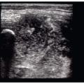
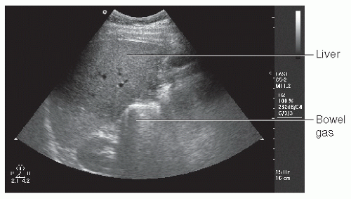 FIGURE 2.4. Solid Organs. Note the well-defined liver but poorly defined bowel gas. Bowel gas causes scattering of the signal and loss of resolution. |
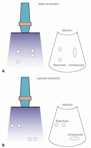 FIGURE 2.5. Examples of Axial and Lateral Resolution. Axial resolution is in line with the scanning plane (A). Lateral resolution is perpendicular to the scanning plane (B). (Redrawn from Simon B, Snoey E, eds. Ultrasound in Emergency and Ambulatory Medicine. St. Louis, MO: Mosby-Year Book; 1997.) |
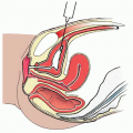
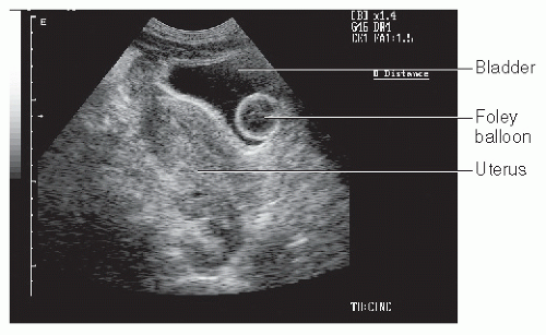 FIGURE 2.6. Acoustic Window. The bladder displaces bowel gas and provides an acoustic window to the uterus. (Note the inflated Foley balloon in the bladder.) |
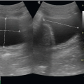
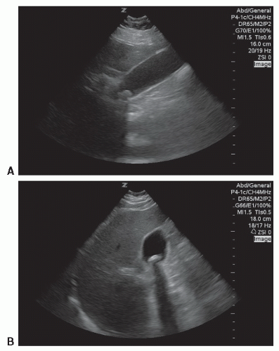 FIGURE 2.7. A: The liver is an excellent acoustic window for the fluid-filled gallbladder. B: The large gallstone creates a dark shadow. In addition, the tissue behind the gallbladder is more echogenic than surrounding tissue. This is enhancement artifact. |
ARTIFACTS
Artifacts are echo signals and images that do not accurately represent the tissue. Artifacts can cause images to appear that are not present, may fail to visualize something that is present, or may show structures at an incorrect location, size, or brightness. Artifacts are, however, predictable and useful. At times, they provide a distraction; at other times they may be used to make a diagnosis. Some artifacts are characteristic for normal tissue (A-lines in lung ultrasound); others are used to diagnose pathology (e.g., shadowing characteristic of gallstones). The following section lists commonly encountered artifacts.
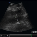
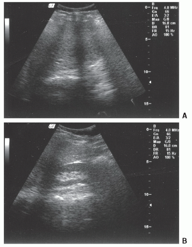 FIGURE 2.8. Ribs Cause the Complete Attenuation of Signal and Generate a Shadow. Rib shadows interfere with scanning through an intercostal approach for the liver (A). Ribs commonly interfere with imaging the kidneys (B). |
Shadowing
Shadowing is one of the most common and useful artifacts to understand in diagnostic ultrasound. Shadowing is an anechoic signal caused by failure of the sound beam to pass through an object. It is typically seen when bone is encountered. Bone is a sharp reflector that prevents the transmission of the signal beyond it. This leaves an acoustically silent space that appears black in the ultrasound image, creating a “shadow.” Shadowing beyond bone tends to be black and sharply defined, referred to as “clean” shadows. In contrast, the ultrasound may be scattered and distorted by gas, creating a gray ill-defined shadow that is referred to as “dirty” shadows. Clean shadowing is often a sign of a gallstone (Fig. 2.7); dirty shadows may indicate gas in the soft tissues in the face of a necrotizing infection.
Related posts:
Stay updated, free articles. Join our Telegram channel

Full access? Get Clinical Tree


