Outer diameter
<6 mm
Imaging fibre bundle
Single fibre diameter
<15 μm
Number of fibres
>15,000
Focus
5–30 mm
Angulation of distal end
60 ° at 30 mm from distal end
Length of the rigid part of distal end
<10 mm
Total length
∼1 m
Field of view
80 °, prograde
The companies started to work on the implementation resulting in two slightly differing realisations as outcome of this competition. The first prototype of Machida was shown to the public in summer 1966 – without working channel and limited angulation. The seventh version was finally the one to become commercially available under the name Machida One in 1967. Olympus worked in parallel and manufactured a first prototype in August 1966 under the model name Olympus No 1. During the year 1967–1968, several design modifications improved the handling and specifications remarkably. These years can be considered as the starting point of flexible fibre bronchoscopes finding their way into the pulmonary departments worldwide.
Evolution of Flexible Bronchoscope Design
A fast penetration contributed to a swift gathering of valuable early adopters’ feedback. The experience from specialised respiratory centres proved to be a solid basis for advice on how to further enhance the bronchoscope. In the following years, bronchoscopes were already available in a variation of different models (see Fig. 2.1), targeting different applications.
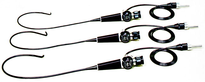
Fig. 2.1
Three early bronchoscope models with different outer diameter (Olympus)
The first bronchoscopes were based on fundamental technology available for gastroenterologists for examination of the GI tract (see Fig. 2.2). The major technical challenge was the required thinner flexible shaft of the bronchoscope. It had to accommodate a sufficient number of glass fibres to transport the light into the lumen, a high precision fibre bundle to transport the image from the distal end of the scope to the eyepiece. Via the ocular piece at the proximal end, the physician can observe the area of interest. The proximal tip of the bronchoscope can be angulated by a lever which is located at the control section – the central part of the scope the user is holding and manoeuvring the scope with. Different to GI scopes which usually allow deflection of the distal tip in all four directions (up/down, left/right), the bronchoscope can be bent only in two directions 180°and 130°, respectively. A measure to safe space, as such a strategy requires only two wires to run inside the shaft. By clockwise or counterclockwise shaft rotation, the bronchoscope tip can reach all areas of interest. A working channel, sometimes called instrument channel, provides aspiration possibilities and guides thin long instruments, so-called endotherapy devices, to, e.g. acquire specimen during the procedure, allowing subsequent histopathological examination.
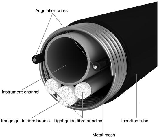
Fig. 2.2
Details of the internal arrangement of components
Imaging Fibre Bundle
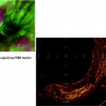
The imaging fibre bundle is a key component of a flexible fibre bronchoscope and determines the image quality. The clearer and more well defined the image quality, the more support it delivers to the diagnosis of the lesion and suggests options for further treatment planning. The challenge is that each single fibre has exactly the same dimension and is positioned at the identical position at both ends of the fibre bundle. If this is not achieved, the image quality is impaired and artefacts disturb the image (see Fig. 2.3).
Fig. 2.3
Importance of fibre bundle arrangements
Channel System Inside the Fibre Bronchoscope
For various purposes, channels are running through the bronchoscope. The first one is starting at the control section down to the distal tip. It is used for aspiration of mucous – and consequently called suction channel. A suction valve at the control section is connected via a tube to an external suction pump. By pushing this valve, the bronchoscopist can activate the suction function. Slightly deeper at the lower part of the control section, a second port is available, the so-called instrument channel port. Through a different valve at this port, endotherapy instruments can be inserted into the bronchoscope to reach the lesion of interest inside the bronchial tract. Thus allowing, e.g. to guide biopsy forceps and to retrieve specimen for further investigation. Sometimes, it is therefore also called biopsy channel. As a space-saving measure, the instrument channel joins the suction channel at the lower part of the control section.
Light Source
In addition to the bronchoscope, the user needs a light source which delivers the light along the glass fibre bundles down to the lumen of interest. The bronchoscope is connected to the device while the examiner is observing the illuminated lumen through the eyepiece (see Fig. 2.4).
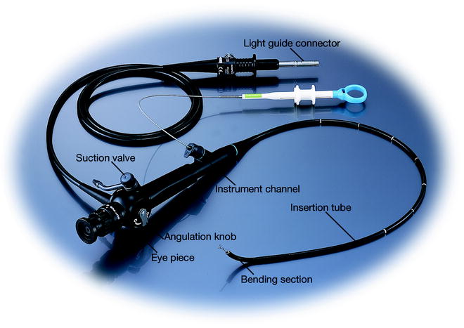
Fig. 2.4
Principle design of a fibre bronchoscope
Suction Pump
Finally, to complete the system, a pump is required which is connected to the suction channel connector. In case the examiner is activating the valve at the control section, visibility interfering mucous can be aspirated through the channel system to clear the view.
Principles of Airway Image Acquisition
Over decades, a wide range of fibre bronchoscopes have been in use in daily routine. The continuous advances in endoscopy design and especially the introduction of video technology – a key breakthrough and a quantum leap for the image quality – influenced the bronchoscope evolution (see Fig. 2.5). The core component needed is the CCD chip (charged coupled device) which delivers as a light-sensitive analogue device the image as a electrical signal and is mounted at the distal tip just behind a lens system (see Fig. 2.6).
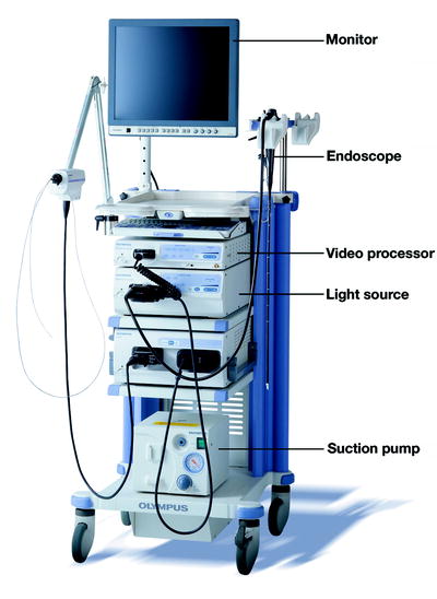
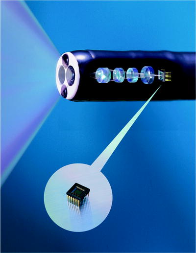
Fig. 2.5
Example of a complete modern endoscopic system
Fig. 2.6
Internal arrangements of lenses and CCD in the scope distal section
The major technical challenge was the miniaturisation of the CCD chip enough that the human anatomy can accommodate the outer shaft dimension of such a video bronchoscope. In comparison to a fibre scope, the image glass fibre bundle requires less space compared to the CCD sensor. The eyepiece though is no longer necessary. Wires deliver the electrical video signal to the light guide connector (see Fig. 2.7).
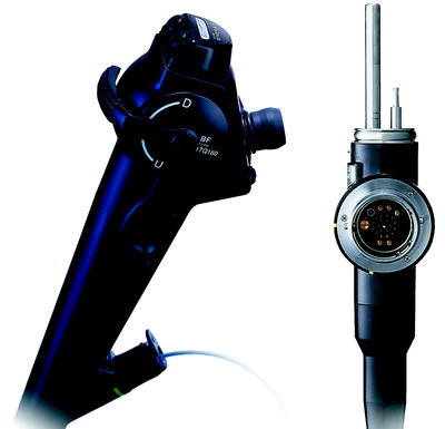
Fig. 2.7
Handle and light guide/image connector of a modern video bronchoscope
In addition to the light source, a video processing unit is now mandatory. After looping the signal through a connection to the video processor with relevant signal processing measures, the user observes the endoluminal image on a monitor linked to the video processor (see Fig. 2.8).
Fig. 2.8
System design of modern video endoscopy
Related posts:

Stay updated, free articles. Join our Telegram channel

Full access? Get Clinical Tree


