Fig. 1.1
(a) Schematic diagram showing the principle of high intensity focused ultrasound (HIFU). (b) Slice of ex-vivo bovine showing a HIFU lesion. (c) Histological section showing the sharp demarcation between ablated and unablated cells (Hematoxylin and Eosine staining). (d) Schematic diagram showing the formation of confluent regions of ablation
1.3 History of HIFU
Since this use of high intensity focused beams was first proposed in ~1942 (Lynn et al. 1942), it has been explored for a number of different potential medical applications. The aim in the 1940 and 1950s was to destroy regions of the brain selectively, in the quest for a better understanding of neurobehavior (Fry et al. 1954, 1958; Fry 1953; Fry and Fry 1960). These early efforts were hampered not only by the poor quality of the ultrasound images used for targeting, but also by the necessity of removing a portion of the skull to provide an acoustic window for the focused beam into the brain. Despite these limitations, it was possible to destroy pre-determined regions of the brains of experimental animals with good selectivity, and some human treatments of Parkinson’s disease were also carried out (Ballantine et al. 1960). The early work achieved ‘focusing’ by using several plane transducers whose beams all crossed in the same plane. The development of HIFU coincided with the introduction of the drug L-dopa. From a patient’s perspective, L-dopa proved to be a more acceptable treatment for Parkinsonism, and from a clinical viewpoint, was easier to administer.
HIFU did not really gain significant clinical acceptance until the 1990s, despite successful ophthalmological treatments before this date. The first proposal to use focused ultrasound in ophthalmology came from Lavine et al. (1952) who demonstrated cataract formation when the lens of the eye was targeted with a focused beam. Other studies demonstrated that HIFU can decrease intra-ocular pressure (Rosenberg and Purnell 1967) and produce lesions in the vitreous, lens, retina and choroid (Coleman et al. 1980, 1985a, b; Lizzi et al. 1978). The first human treatments of glaucoma, undertaken in 1982, gave encouraging results. 79 % of the patient cohort treated had a sustained lowered intra-ocular pressure after 1 year (Silverman et al. 1991). Although HIFU showed considerable promise in these, and other, ophthalmological applications, laser surgery has enjoyed wider success and application, presumably because of its apparently simpler technology and application. It is only now that the use of HIFU in the treatment of glaucoma is being revisited, with considerable success (Aptel et al. 2014).
Overview of clinical usage
The realization of the full potential of HIFU treatments is only possible now that precise targeting and good treatment follow-up techniques, (with anatomical and functional imaging), are available with modern diagnostic ultrasound scanning and magnetic resonance imaging (MRI) methodologies. The provision of real-time images with excellent spatial resolution and contrast has opened a window of opportunity for HIFU which can only be used to full advantage when the tissue volume to be destroyed can be precisely targeted. Both ultrasound and MRI have been used to guide and monitor HIFU treatments. Each method comes with its advantages and disadvantages. MRI gives anatomical images, and can provide thermometry sequences that allow the tissue temperature to be mapped, thus providing information not only about the success of ablation in the target, but also about the safety of critical regions outside this volume. While ultrasound thermometry has not yet found clinical implementation, this modality offers superior spatial and temporal resolution for imaging. Confirmation of successful ablation under ultrasound guidance relies on the appearance of bright echoes on an ultrasound scan, The ability of HIFU to ablate subcutaneous tissue volumes non-invasively has made it an attractive potential therapy for deep-seated soft tissue tumors. Malignant tumors of the liver, kidney, breast and pancreas have been successfully targeted (Al-Bataineh et al. 2012; Orsi et al. 2010; Wu et al. 2004, 2005a, b). While ultrasound does not significantly penetrate bone, many osteosarcomas break through the bone cortex, and thus are also good candidates for HIFU treatment (Li et al. 2010; Chen and Zhou 2005). The successful palliation of pain resulting from bone tumors has also been reported, with the treatment here being aimed at destroying the nerves lying on the peri-osteum (Liberman et al. 2009; Hurwitz et al. 2014). Care must be exercised to avoid bowel gas that lies in the propagation path. In some treatment orientations this gas may be successfully displaced by applying pressure from a water balloon placed against the abdomen. HIFU has proved to be an attractive technique for the treatment of uterine fibroids. These may be clearly visualized on either MR or Ultrasound images (Froeling et al. 2013; Hesley et al. 2013; Quinn et al. 2015).
Trans-rectal HIFU treatment of prostate tumors has also been widely investigated. Both benign prostate hyperplasia (BPH) and prostate cancer have been targeted (Crouzet et al. 2015; Thüroff and Chaussy 2015). Initial results from clinical trials for treatment of BPH (Gelet et al. 1993; Sullivan et al. 1997) were encouraging, with increase in flow rate and decreases in post-void residual volume. However, the long-term results of Madersbacher et al. (2000) were disappointing, with 44 % of patients requiring a salvage trans-urethral resection of the prostate (TURP) within 4 years. HIFU has thus not proved to be significantly better than the “gold standard” treatment (TURP). Treatment of cancer in the prostate presents different problems from those associated with the treatment of BPH (Crouzet et al. 2015; Thüroff and Chaussy 2015). Prostate cancer is a multi-focal disease, the foci of which are difficult to detect with diagnostic ultrasound. It is important for its control that all foci are destroyed. Initially HIFU treatments were aimed at ablation of the whole gland (Chaussy et al. 2001; Dickinson et al. 2013). More recently, there has been a move towards partial ablation, with either hemi-ablation, or focal ablations (Crouzet et al. 2014; Baco et al. 2014; Valerio et al. 2014). There is little in the way of conventional therapy to offer patients whose prostate cancer recurs after radiation therapy. High intensity focused ultrasound may be able to fulfill this role as it offers selective tissue destruction without side effect. Early trials for this application have shown encouraging results (Ahmed et al. 2012; Gelet et al. 2004).
1.4 Exposure Dosimetry
In imaging and therapies that use ionizing radiation, a distinction is clearly made between “exposure” and “dose”, with exposure for these energy forms being the amount of ionization produced in air by X- or γ-rays. The unit of exposure is the Roentgen, R. Exposure describes the amount of radiation that reaches the body, but does not describe the fraction of that incident energy that is absorbed within tissue. A second parameter is used for this, the “absorbed dose” (commonly referred to as “dose”). Dose characterizes the amount of energy deposited per kilogram and has units of the gray (Gy) and the rad, where 1 rad = 100 Gy. A weighting factor (relative biological effect, RBE) is used in an attempt to compare the biological effects of different forms of ionizing radiation. This leads to a “dose equivalent” parameter, whose units are the rem or Sievert, Sv, (1 rem = 100 Sv). These parameters are related by the equation: Dose equivalent (Sv) = dose (Gy)x RBE. X-rays, γ-rays and ß particles have an RBE of 1.0, whereas α particles have an RBE of 20.
The terms “exposure” and “dose” are used interchangeably in medical ultrasound, although a convincing case for drawing the distinction can be made. Different biological effects result from different modes of ultrasonic energy delivery. For example, two exposures that use the same total acoustic energy over an identical time span, where one is delivered in continuous mode, and the other in short pulses at low repetition rate and high amplitude may result in very different effects in tissue. The first is more likely to induce thermal effects, while the second may stimulate cavitation activity and its associated characteristic cell damage (ter Haar 2010).
Ultrasound exposures are most usually characterized in terms of the acoustic field determined under “free field conditions” in water. Here, “free field” is taken to describe the conditions in which the ultrasound beam propagates freely, without influence from boundaries or other obstacles. A full description of HIFU exposures requires knowledge of frequency, exposure time, transducer characteristics, total power, acoustic pressure and/or intensity (energy flux in Watts.cm−2) and mode of energy delivery (single shots, scanned exposures, etc.) (ter Haar et al. 2011).
In order to make the transition from exposure to dose in an ultrasound field, it is necessary to know the acoustic characteristics of the propagation medium. The parameters of most importance are the attenuation and absorption coefficients, the speed of sound and the nonlinearity parameter B/A. There are large gaps in knowledge about these parameters for both normal and malignant human tissues, although many have been tabulated (Goss et al. 1980; Duck 2013). Generally HIFU exposures are described in terms of free field water measurements, but in some cases, an attempt is made to calculate an in-situ intensity by estimating the total attenuation in the beam path. Spatial peak (focal peak) intensities and spatially averaged intensities are also sometimes quoted.
Two dose parameters related solely to thermal effects have been proposed. Sapareto and Dewey (1984) proposed a thermal dose parameter. This has been used extensively to describe hyperthermic cancer treatments. The temperature-time history for a particular tissue volume is integrated and reduced to a biologically equivalent exposure time at 43 °C, t43. This equivalent time is given by the equation:
where R is 0.5 above 43 °C and 0.25 below 42 °C, and T is the average temperature over a time Δt.
(1.1)
This has been shown to be valid up to about 50 °C, but is difficult to validate experimentally for the short times required above this temperature, since very fast heating and cooling rates are required. An alternative parameter related to the heating potential of the HIFU beam is the product of intensity and time (a measure of the total energy), but this concept has not gained widespread acceptance in the therapy ultrasound literature. Clinically, a t43 of 240 min is used as the threshold for successful thermal ablation (MacDannold et al. 2006). It is now well accepted that cavitation can enhance the heating in a HIFU field (Holt and Roy 2001; Khokhlova et al. 2006). However, there is, as yet, no validated method of quantifying cavitation activity, nor accepted method for defining “cavitation dose” (Chen et al. 2003; Hwang et al. 2006).
1.5 HIFU Treatment Delivery
The devices used to deliver HIFU clinically are broadly divided into two classes, extra-corporeal and interstitial. The basic components however, do not differ much, comprising as they do, the transducer, a signal generator, amplifier, matching circuitry to maximize the electro-acoustic efficiency, a power meter, and in some cases a method of cooling the transducer. These are connected to an operator console that allows movement and positioning of the source, and also provides a means of monitoring the treatment.
The focusing required for HIFU treatments can be achieved in a number of ways. The simplest is to use a single element transducer: most commonly, either in the form of a planar disc fronted by a lens, or shaped as a spherical bowl. Such transducers are limited in that they can only provide a fixed focus, and if clinically relevant volumes are to be treated, the whole transducer assembly must be physically moved in order to place lesions side by side (Fig. 1.1d). The more common alternative is to use multi-element transducer arrays. Electronic phasing of the signal to individual elements allows both flexibility in shaping the focal volume, and some dynamic control of its position, both axially and trans-axially (Gavrilov et al. 2000; Gavrilov and Hand 2000; Daum and Hynynen 1999). The geometry of the elements determines its capabilities. For example, if the array is comprised of concentric elements (an annular array) it is only possible to move the focus electronically to different positions along the beam axis (Hynynen et al. 1996; Dupenloup et al. 1996).
When the individual elements are placed on a spherical shell, focusing is achieved using both the transducer’s geometry, and dynamic control of phase and amplitude. For the safe application of HIFU it is important to minimize the grating lobes that can occur when elements are uniformly spaced. These, and other secondary maxima that can be present in the acoustic field, may lead to unwanted local heating in tissue away from the target volume. A number of solutions for reducing grating lobes have been suggested. In the main, these involve destroying the regular periodicity of the element spacing, and introducing randomness and sparsity into their arrangement (Hutchinson et al. 1996; Goss et al. 1996; Gavrilov et al. 1997; Filonenko et al. 2004; Hand et al. 2009). Random arrays typically allow lateral movement in the focal plane by distances of ~10 % of the geometric focal length. Pernot et al. (2003) compared the steering capabilities and appearance of side lobes at a frequency of 0.9 MHz for three sparse array geometries (hexagonal, annular and quasi-random), each with 52 % coverage of the 180 mm diameter, 120 mm geometrical focal length spherical surface on which they were mounted. They showed by simulation that the quasi-random design gave the best beam steering capability while maintaining sufficient peak pressure amplitude. Their results were validated by experiment. In Figs. 1.2, 1.3 and 1.4, field simulations for a 256 element random array are displayed, showing the influence of the beam pattern of the number of array elements (Fig. 1.2), the radius of curvature of the bowl on which they are placed (Fig. 1.3), and the drive frequency (Fig. 1.4).
Fig. 1.2
Effect of changing number of elements. 20 cm radius of curvature, 20 cm diameter, 1.7 MHz, 5 cm diameter central aperture
Fig. 1.3
Effect of changing radius of curvature (RoC). 256 elements, 20 cm diameter, 1.7 MHz, 5 cm diameter central aperture
Fig. 1.4
Effect of changing frequency. 256 elements, 20 cm radius of curvature, 20 cm diameter, 5 cm diameter central aperture
A disadvantage of the sparse array is that energy is deposited incoherently in the near field (Payne et al. 2011). This leads to a low level of heating that becomes problematic when focal lesions are to be placed side by side (to gain confluent ablation volumes) with their near fields overlapping, since the temperature may rise to biologically significant levels. This is avoided by introducing a cooling time between “shots”, but this in turn lengthens the treatment time. In order to reduce these problems, a 500 kHz flat phased array with elements space λ/2 apart has been proposed (Ellens et al. 2015). While this reduces the effects of near field heating, and avoids the problem of grating lobes, this lower frequency (necessary if the λ/2 separation is to be achieved), results in a lower spatial resolution and cavitation threshold, and increases the probability of heating post-focally. At this lower frequency, the ultrasound absorption is reduced, and more acoustic power is required to achieve the desired temperatures than for the 1–3 MHz frequency range that is more commonly used. This illustrates the necessity, common to all designs, of making trade offs and compromises Hill et al. 1994.
It is not possible here to describe in detail the many different transducer geometries available, but Table 1.1 summarizes the many different designs, their steering capabilities, and their advantages and disadvantages.
Table 1.1
Summary of available transducer geometries, their advantages and disadvantages
Transducer geometry/composition | Steering capability | Significant grating lobes? | Cover (packing fraction) | Capable of bone sparing | Application | References |
|---|---|---|---|---|---|---|
Single element Planar + lens Spherical bowl Toroid Cylinder | None, mechanical translational only | No | 100 % | No | Abdomen, breast, prostate Abdomen, breast, prostate Liver – intra-operative Ophthalmology – glaucoma | |
Multi-element Annular array | Only in axial direction | No | ≈100 % | No | Abdomen, breast | |
Multi-element Toroid array | Limited | No | ≈100 % | No | Liver – intra-operative | Vincenot et al. (2013) |
Multi-element Periodic array | Limited | Yes | High | Yes | Abdomen, breast, prostate | |
Multi-element Periodic array λ/2 spacing | Yes, limited | No | Variable | Yes | Abdomen, breast, prostate | Ellens et al. (2015) |
1.5D array | Only in lateral direction | Depends on element spacing | High (variable) | (Yes) | Abdomen, breast, prostate | |
Multi-element Aperiodic, random, sparse array | Yes ≈10 % focal length laterally | No | Reduced | Yes | Abdomen, breast, prostate, brain | |
Multi-element Randomly sized elements (including sector arrays, strip arrays) | Yes | No | Variable | (Yes) | Abdomen, breast, prostate |
When tissue targets lie behind the ribcage (such as those in liver, kidney or pancreas) or under the skull, approaches that avoid overheating the bone surface are required if an acoustic window is not to be created by surgical removal of some skull or ribs. For the rib cage, simple ray tracing may be used to “turn off” elements whose beam impinges on the bone (Civale et al. 2006) or, more sophisticatedly, time reversal or adaptive focusing techniques are used (Pernot et al. 2003; Tanter et al. 1998, 2001; Thomas and Fink 1996; Clement and Hynynen 2002a, b; Aubry et al. 2008). Using these techniques, selective regions lying behind bone can be targeted, and clinically, they have been used successfully in the treatment of essential tremor and other neurological problems (Medel et al. 2012; Martin et al. 2009; Elias et al. 2013). The ultrasound field is severely distorted in amplitude and phase by passage through the skull. Time reversal can correct the phase aberrations induced by the skull bone, and when combined with amplitude correction, is used to restore the desired focus at the brain target. The time reversal technique relies on the reciprocity property of the wave equation, and requires the presence of a sensor at the anticipated focal point in the brain to record the aberrations, which disrupt the focus. The implantation of such a sensor is clinically unrealistic, but it has been shown that it is possible to perform the required phase and amplitude corrections using either magnetic resonance (MR) or computed tomography (CT) images of the skull to model its ultrasonic properties for use in numerical modeling of the wave front distortion (Hynynen and Sun 1999; Aubry et al. 2003). This allows the propagation of a wave front emanating from a virtual point-like source in the brain (the intended “target”) through the skull to be simulated and recorded by a set of virtual receivers outside the head. This wave front can be time reversed, and emitted by a real transducer array. This, along with amplitude correction made possible by knowledge of the porosity of the bone obtained from the CT scan, results in a focused beam at the brain “target” (Aubry et al. 2003).
1.5.1 Transducer Materials
There are a number of constraints that must be considered in the design of a therapy ultrasound transducer. Apart from the obvious necessity of the ability to produce high powers at frequencies in the range 0.25–10 MHz (requiring high electro-acoustic conversion efficiency), they must be reliable, able to deliver energy in pulsed or continuous wave form, and be physically compatible with the chosen imaging methods. Compatibility with the high magnetic fields present during MR guided HIFU is clearly a technological challenge. When ultrasound is the monitoring modality of choice, a central aperture is usually required in the therapy transducer, into which an imaging probe can be inserted. There is increasingly a call for transducer elements that are dual mode, that is, are capable of operating both as therapy sources at high power, and of being used in short pulse, imaging mode (Ebbini et al. 2006; Owen et al. 2010; Mari et al. 2013; Casper et al. 2013).
Multi-element arrays are most commonly constructed in one of two ways. Individual elements can be cased in separate housings and then mounted individually on a shell of the required geometry. This allows easy replacement of failing elements and gives flexibility in their arrangement, but only allows for sparse arrays. An example of such a multi-element array is shown in Fig. 1.5. The alternative is to create an array by, for example, cutting deep grooves into a single piezo-ceramic sheet. This allows for denser packing of the elements, but can create a fragile array when larger sizes are required. Hybrid combinations of these two methods are also possible.
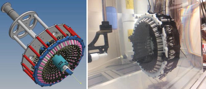
Fig. 1.5
Multi-element pseudo-random array composed of 256 individual elements mounted in 3D printed shell
With few exceptions (most notably for lithotripsy), medical ultrasound transducers are made from piezo-electric materials. Early pioneers in this area used the naturally occurring material, quartz (Fry 1953, 1977; Fry et al. 1954). Piezo-electricity was first discovered by Pierre and Jacques Curie in the 1880s, and is the name given to the property of a crystalline material that develops a charge when it is subjected to mechanical stress. The inverse effect is that when an electrical charge is applied to such a material, it will change its shape. An alternating current applied across a piezo-electric disc will cause rapid movement of its faces, creating a pressure wave in the medium in which it sits. Naturally occurring piezo-electric materials other than quartz include sucrose, tourmaline, lead titanate and dry bone.
In medical ultrasound, the most commonly used piezo-electric material is now lead zirconate titanate (Pb[ZrxTi1-x]O3, PZT). Low loss PZT ceramic is cut into discs, the thickness of which determines the resonant frequency, the higher the frequency, the thinner the disc. In order to reduce fragility it is often convenient to drive these transducers at their third harmonic. For high power applications, PZT ceramic transducers are commonly air backed, to allow cooling and to reduce damping of the pressure wave. While high-density arrays can be made from simple piezo-electric materials, they operate in a narrow bandwidth, and it is necessary to avoid cross talk between adjacent elements of the array.
An alternative to using the piezo-ceramic crystals on their own is to incorporate them into a piezo-composite structure (Chapelon et al. 2000). Here, pillars of piezo-ceramic material are embedded in a polymer. The presence of the polymer enhances the vibration in the thickness mode used to generate the ultrasound wave, and reduces cross talk between the elements. The transducer shell can be shaped, and a solid backing material can be used, rendering the transducer less fragile. A common geometry for piezo-composites used in therapy ultrasound is 1–3. This describes the continuity of the piezo-ceramic in one dimension (a pillar) and the 3D continuity of the embedding polymer.
Related posts:
 Heat-Based Tumor Ablation: Role of the Immune Response
 MRI-Guided HIFU Methods for the Ablation of Liver and Renal Cancers
 Design of Microbubbles for Gene/Drug Delivery
 Co-administration of Microbubbles and Drugs in Ultrasound-Assisted Drug Delivery: Comparison with Drug-Carrying Particles
 Stimulation of Bone Repair with Ultrasound
Stay updated, free articles. Join our Telegram channel

Full access? Get Clinical Tree


