This article explores the role of high-field (HF) MR imaging in medicine. It analyzes advantages of HF MR imaging in application to human subjects and how best they can be used to unravel the secrets of diseases, such as multiple sclerosis. Special emphasis is placed on morphologic imaging to highlight the role of soft tissue contrast, MR spectroscopy to showcase the ability of detecting biochemical information, and functional MR imaging as an emerging technology for assessing tissue function with the possibility of eventual introduction to the clinical arena. In this article, hardware issues, such as RF coils for HF systems with a static magnetic field of 3.0 T or higher are also discussed.
Since its discovery, magnetic resonance (MR) has displayed capability for noninvasively transmitting information from the internal structures of opaque objects. Introduction of gradients in the 1970s and its subsequent evolution into an imaging tool capable of revealing structure and function of biologic tissues has transformed MR imaging into an invaluable biomedical research method. En route, clinical MR imaging operating at 1.5 T has also emerged as the most powerful modality for the study of the central nervous system (CNS). In addition to visualization of morphology, it has brought medicine other potentially powerful tools: functional MR imaging (fMR imaging), spectroscopy (MRS), and diffusion tensor (DT) MR imaging. These tools have enabled MR imaging access to functional and microstructural aspects of the CNS.
Morphologic MR imaging enjoys a high signal-to-noise ratio (SNR) compared with other imaging modalities enabling it to acquire high-resolution images from the CNS. The contrast-to-noise ratio (CNR) has been primarily governed by spin relaxation of spin-lattice (T1)–type and spin-spin (T2)–type; this has bestowed on MR imaging a high CNR for soft tissues. MR imaging suffers from low pathologic specificity for many diseases. Integration of various MR modalities has been advanced as having the potential for enhancing specificity of MR imaging. The low SNR of some of these modalities (eg, MRS at 1.5 T) has prevented the potential of multimodality from being realized. At higher fields (4.0 T), MR imaging has demonstrated ability to produce robust functional and spectroscopic data to achieve such integration of techniques under one protocol. It is known that the functional manifestations of a disease could possess genuine information in the presence of a normal structural image. The same argument applies to the relationship between spectroscopic and morphologic images. As such, methods of improving quality of MR data are vigorously investigated.
This article explores the role of high-field (HF) MR imaging and ways that its advantages can best be used to unravel the secrets of diseases, such as multiple sclerosis (MS). Special emphasis is placed on morphologic imaging to highlight the role of soft tissue contrast, MRS to showcase ability of detecting biochemical information, and fMR imaging as an emerging technology for assessing tissue function with the possibility of eventual introduction to the clinical arena. In this context, HF indicates systems with a static magnetic field of 3.0 T or higher.
Physics of imaging
In all imaging techniques some form of wave, electromagnetic or sound, is used and the extent of absorption of individual atoms is manifested in an absorption or reflection map that makes up the image. A distinct aspect of these imaging methods is the characteristic time that interaction with matter takes (eg, of the order of nanoseconds in photography); these imaging techniques can produce images almost instantaneously. On the other hand, the interaction occurring between the electric field of the wave and the accelerating electrons of the subject attenuates the beam intensity, allowing an image to be formed. Because of the ability of electrons of the object to absorb the electric field oscillating at almost any frequency, the electric field strongly interacts with the tissue as it penetrates into the body. This characteristic of absorption imaging requires no preparation of the subjects, unlike MR imaging that uses radiofrequency (RF) waves that readily penetrate the biologic tissues. To achieve this, MR imaging requires a large magnet to “prime” the subject for RF absorption. On the other hand, the high energy of x-ray photons is capable of ionizing atoms and molecules while at the same time interacting strongly with the nucleus that limits the amount of waves that could be used for such imaging devices.
MR uses the magnetic field of electromagnetic waves in the RF range. RF waves have frequencies in MHz range (10 8 Hz), whereas x-rays have a frequency in AHz range (10 18 Hz). Several physical quantities are involved in interaction of electromagnetic waves with matter, some of which are vectors and others are scalar quantities. In this section and throughout this article, vector quantities are designated by boldface and scalar quantities by regular fonts. Unlike electrons, which are monopoles, magnets require a dipole (ie, a magnetic dipole moment [ μ ]) with which to interact. This dipole is provided by the spinning action of the charged particles in atoms. Electrons and protons are charged particles and they spin. Spinning action assigns an angular momentum S to each particle. Interaction of the oscillating magnetic field ( B 1 ) of an RF wave at a frequency of ω with a proton of μ magnetic moment is governed by the internal structure of the proton manifested in gyromagnetic ratio, γ, according to μ = γ S. Clearly, on exposure of matter to a strong magnetic field ( B 0 ), its protons will begin a presessional motion with a frequency known as Larmor frequency ω L = γ B 0 . Resonance condition is produced when an RF coil is tuned such that its frequency ω = ω L enables its B 1 field to couple with precessing protons and transfer energy to them. The process is known as excitation. This narrow resonance condition is what imposes a stringent demand on the design and operation of RF coils. These coils can deliver a powerful RF pulse at resonance frequency ω L to objects within a magnetic field ( B 0 ) during the transmit path and absorb energy from the B 1 field of the protons during the receive path, which constitutes the MR imaging signal.
Absorption of RF causes protons to deflect away from the parallel direction with B 0 , a process comparable to absorption of x-ray or light beam by atoms and molecules in CT and routine photography. The realignment of μ with B 0 is achieved through the mechanism of spin-lattice (T1) relaxation. T1-weighted images (T1W) produce one of the highest SNR sequences in MR imaging. Because T1 of various biologic tissues are of the order of 1 second, relaxation greatly slows down this imaging process. The need for repeated excitation of protons and detection of their emitted RF field while relaxing back to their equilibrium state makes a typical image with 256 × 256 pixels requiring roughly 256 seconds or about 4 minutes to acquire. Another important process in MR imaging is spin-spin relaxation or T2 decay. This process becomes significant because μ of individual atoms are not detectable at achievable B 0 in MR imaging scanners and that is why the sum of μ of a group of molecules within an imaginary box or voxel within the tissue is used. The net magnetic moment of this group is called magnetization vector or M . The magnitude of M depends on the extent of alignment of individual μ within the voxel. A maximum alignment is achieved in equilibrium and immediately after delivery of an RF pulse at ω L . Because of local inhomogeneities in B 0 , however, coherent precession of M about B 0 is lost over time. This loss of alignment occurs at a rate known as spin-spin relaxation or T2. T2-weighted (T2W) images in MR imaging are rich with information about local structures. The use of T1W images is another way that MR imaging can produce brain maps with distinct contrast between various tissues, which is clinically useful in MS. Many other useful contrast mechanisms are offered by MR imaging, which may be sensitive to many aspects of CNS pathology of MS. This multiple means of accessing biologic tissues during the same session makes MR imaging the ideal technique with multimodal approach to the study of a disease.
High-field MR imaging
Soon after the appearance of MR imaging scanners for medical applications, 1.5 T was recognized as the high field strength for clinical scanners. This field strength was later accepted as the standard clinical field for MR imaging scanners. Nevertheless, efforts by researchers to test the advantages and viabilities of higher fields began right away. Research scanners have always shadowed the clinical scanners keeping research field strengths higher than their clinical counterparts. During the 1980s and early 1990s, when the standard clinical filed was 1.5 T, the B 0 of research scanners stood at 3.0 T and 4.0 T. Despite their limited numbers, the researchers using 4.0 T whole-body scanners worked on many important issues, such as feasibility of imaging at HF, safety, RF coil and gradient design, and pulse sequence development, which paved the road for the development of 3.0 T scanners by major manufacturers for clinical uses.
A similar history is now unfolding for higher fields. An 8.0 T whole-body scanner was developed in the mid-1990s, which was followed by manufacturers’ development of whole-body 7.0 T scanners of today. At present, some 20 institutions around the world have received commercial 7.0 T MR imaging scanners and another 30 will be in possession of these devices within the next 5 years, raising their total to around 50. This trend is remarkable considering that only a handful of 4.0 T scanners were built in the late 1980s and 1990s as a precursor to today’s clinical 3.0 T scanners. A flurry of HF technology development has erupted in which, for a large part, efforts have been focused on the understanding of problems of MR imaging at high fields. These researchers have produced many innovative solutions to many challenges of HF imaging. These challenges include magnet design, safety, RF coils, artifacts, slow imaging process, and so forth. The understanding of these issues will help appreciation of their role in the progress of this field and will contribute to the incorporation of HF MR imaging in biomedical research.
The magnet
Some difficult constraints have to be incorporated in the design of magnets for human applications, primarily because of the need to contain the human body within the scanner. Cylindrical wire wounds or solenoids have been shown to have solutions for Laplace equation ∇ 2 B Z = 0, which has spherical harmonics as its solution in the form of terms called Legendre polynomials. Solutions of equation with spherical symmetry determine magnetic field components due to each current loop in the central regions of the magnet. Generation of axial magnetic field at the center of the magnet at the space required to image major human organs places constraints on the size of the magnets. The central region is called diameter spherical volume (DSV) and is about 50 cm, allowing images of regions as large as the human abdominal section within the scanner. It is conceivable that magnets with fields even higher than 9.4 T, which is currently the highest field for human MR imaging, will be designed and built in the future. HF magnets appropriate for MR imaging built as solenoids of superconducting wires capable of carrying hundreds of amperes are likely to be designed with alloys capable of currying higher currents or more wires wound around the former. NbTi is the alloy used in almost all magnets built for biomedical applications with field strength of up to 10 T, because of the current density that these wires can carry within their own magnetic fields. This phenomenon makes fields greater than 10 T difficult to attain for whole-body magnets of NbTi because the reduced current density in the wires requires the use of massive amounts of superconducting wires that makes such designs unfeasible. These magnets should operate at less than NbTi critical temperature, Tc = 10 K, making 4.2 K, the boiling temperature of liquid helium (LHe2), appropriate for sustained NbTi superconductivity. To achieve higher fields, one could pump on LHe2 to drive the temperature to 1.8 K, which is the triple point of LHe2; this allows fields of up to 15 T to be attained with this technology. Another approach would be the use of NbSb, which can produce fields of up to 15 T at 4.2 K. One consequence of present technology is the massive size and weight of the scanners. All present HF MR imaging whole-body scanners use NbTi; they weigh up to 30 tons and contain up to 80 MJ of energy. The magnets are about 3 m long and equally high. Their shielding would add to their weight and size. The cryogenic technology of closed-cycle refrigeration has greatly helped the use of LHe2 consumption for these magnets. The LHe2 boil-off rate of early HF magnets was high, as much as 10 L per day. At present, there are zero–boil off 7.0 T scanners with physical characteristics comparable to those of early generations. For unshielded magnets, 5 Gauss line of the stray field extends to about 10 m axially depending on the bore diameter. The weight of the magnets is roughly 4 ton/T. One way of containing the stray field of the unshielded HF systems is passive shielding that consists of an iron room being built around the magnet. Such B 0 shields could bring the 5 Gauss line to within 2 m of the magnet depending on the amount of steel used to build the shield. For 7.0 T magnets, a B 0 shield of 300 to 400 ton iron will suffice to bring the stray field to within close distances of the magnet. The cost of building such a B 0 shield room is about $500 thousand plus or minus $200 thousand, depending on the location and management of the shield room design and construction.
Safety
The strong static magnetic field used in MR imaging can pose some safety and health hazards to human subjects. These can be divided into three main categories: missile or projectile effect, magnetohydrodynamic (MHD), and RF power deposition.
The missile effect refers to the magnetization of any ferromagnetic material in the near vicinity of magnets. In general, an object with a magnetization vector of M will experience a rotational force or torque of τ = M × B, which will force M to line up with B, here B 0 . This force is the same one that lines up the compass needle with the magnetic field of the earth and lines up the molecular dipole moments μ of water with B 0 in the human body within MR imaging scanners. This torque can be strong enough to cause displacement of medical devices implanted in the human body. Medical devices are usually tested for the values of torque acting on them if they contain ferromagnetic or strongly paramagnetic components. Recently, many medical devices are being tested within the highest field strengths available for human imaging (ie, 7.0 T and higher) to demonstrate their safety. In addition, the presence of static magnetic field inhomogeneity ( ∇ B 0 ) gives rise to a translational force of F = ∇ ( τ ) , which makes the magnitude of F proportional to the product of B and spatial variations of magnetic field ∂ B /∂z. This force is of attractive nature and additionally is proportional to the magnetic susceptibility χ of the object within the field. For HF magnets, given that these magnets have a high B 0 inhomogeneity (∂B/∂z) near the opening of the magnet, the high B 0 will result in a high B 0 ∂B 0 /∂z, which is about 40 T /m. If ferromagnetic objects with high χ are introduced into this region of high B 0 ∂B 0 /∂z, they experience a large attractive force that pulls them toward the center of the scanner. This force, untamed, could turn any ferrous metals brought into the scanner room into a missile zeroed in on its target—the center of the magnet. The impact of such fast-moving objects poses a lethal threat to any living being within the magnet. The missile effect constitutes the most ominous preventable risk for operation of HF magnets.
Another venue for expression of such translational force is the blood within the vessels, the MHD. The high conductivity of blood causes its flow to generate a force due to the B 0 acting on the blood moving in a perpendicular direction to the field. This force generates an electric current normal to the axis of vessels which, in turn, interacts with the magnetic field to generate a force against the blood flow, hence lowering the blood pressure. In the past, it had been estimated that at 10 T a large increase in blood pressure of more than 20% would be needed to neutralize this MHD force to maintain the flow in the aorta. This phenomenon is highly directional and its effect may be averaged out as a result of the randomness of blood vessel directions that causes the blood within them to experience a randomly directed force; this could be one of the reasons that no such change in blood pressure has been observed in studies on animals within HF magnets.
Characteristics of RF waves required for excitation of spins in MR imaging is also a matter of safety. In general, the interaction of electromagnetic waves with objects depends on the relative value of their wavelength, λ, to the dimension of the object, d. As the field strength increases, the proton’s Larmor frequency (f) increases causing λ to decrease proportionally as a consequence of the relationship f = c/λ, where c is the speed of light. Furthermore, the wavelength of RF drops according to λ b = λ / ε as it penetrates into the body with a permittivity of ε. Consequently, the in-tissue wavelength or λ b drops rapidly as B 0 increases. At 7.0 T, where λ = 1 m, the RF penetration into a water phantom will reduce the wavelength to about 11 cm because of the ε of water being around 80. Considering the typical dimension of the human head being around d = 15 cm, at 7.0 T λ b < d, a condition that reveals the wave nature of the RF in its propagation through the medium. This condition establishes a strong inhomogeneity in RF amplitude as it spreads through the medium. Such RF inhomogeneity, in high dielectric media, such as water or human head as shown in Fig. 1 , creates a condition for concentration or focusing of RF waves in a central region. Although the extent of this dielectric resonance is relatively large, it warrants mentioning a condition known as “hot spots” that can pose a health risk to subjects in the extreme case of highly inhomogeneous RF distribution of coils at HF. In this case, efforts must be made to achieve the most homogeneous RF fields possible. It must be noted that although such homogeneous fields are necessary for safe operation of MR imaging scanners at ultra HF, the desirable level of homogeneity might not be achievable with simple designs of RF coils. In addition to safety considerations, RF homogeneity is also essential for uniform imaging. Recent developments in parallel imaging have made much progress in providing uniform RF distribution and elimination of RF focusing at HF. For HF scanners, transmitting surface coils and other specialty coils still could potentially pose a safety concern because they could produce highly nonuniform RF fields. Significance of knowledge of localized heating is that physiologic facility for heat removal from a highly localized internal region is poor, unlike the body’s ability to dissipate heat from superficial tissues. Furthermore, regulatory guidelines for maximum RF exposures usually do not take into account the possibility of localized heating because this is a characteristic of RF coil design and operation. Although one could be within the regulatory limits for RF power application on a human subject, an inhomogeneous RF distribution could still create a potentially hazardous condition for localized internal tissue heating.
Signal-to-noise ratio and contrast-to-noise ratio
The factors affecting SNR are B 0 , RF coil design, pulse sequence parameters, number of averages, voxel size, gradient strength of phase encoding, and receiver bandwidth. From these factors, all but B 0 are changeable after the scanner is purchased. Assuming that all other factors are optimized, therefore, B 0 becomes the sole determinant of SNR.
A static magnetic field of the order of greater than 0.1 T is required to generate images from the magnetic dipoles of atoms and molecules of the human body. Exposure of tissue water to a B 0 = 1.0 T will split the spin population into parallel (−) and anti-parallel (+) in orientation with B 0 . The difference in energy level of E + − E − = ΔE = 2 μ.B 0 will develop as a result of interaction of μ with B 0 . At 1.0 T, this energy difference is about 10 −7 eV or 0.1 μeV. This number should be compared with the atomic energy levels of the order of 1eV and room temperature energy of about 25 meV. In this highly unfavorable environment for detection of MR signal, the resonance coupling of the RF coil with precessing protons drastically reduces the noise spectrum enabling the detection of such feeble signal from the background noise. As the excess population of parallel protons, (ie, the ratio of E + /E − ∼e(−ΔE/kT)) increases, it results in a twofold advantage for detection of their signal. First, it increases the energy gap or ΔE/kT, which means that there is larger population of RF photons. Second, the RF wave or RF photon energies are higher. Both of these effects contribute to higher SNR as B 0 increases. This SNR advantage highlights the role of high magnetic fields in MR imaging.
In the case of 7.0 T scanners, SNR is about five times higher than at 1.5 T. Compared with the typical voxel size at 1.5 T (ie, 1 mm × 1 mm × 5 mm) the SNR at HF indicates that signal from a single voxel is approaching the limits of biologic cells (ie, 10–100 μm). In approaching microscopic detection capability, the role of relaxation rates should also be taken into account. They represent the time scale during which the MR signal persists after it is generated. Although T1 is of the order of 1 second, T2 is almost 10 times shorter for biologic tissues. In addition, relaxation rates are B 0 dependent. T2 decreases while T1 increases with B 0 . At 7.0 T, in vivo T1 values reported for gray matter (GM) are around 2 seconds and those for white matter (WM) are about 1.3 seconds; T1 values at 3.0 T for GM are around 1.5 seconds and those for WM are about 0.8 seconds; and T1 at 1.5 T for GM is around 1.2 seconds and those for WM are about 0.6 seconds. Based on these values, GM/WM contrast at 1.5 T is 0.67, at 3.0 T is 0.69, and at 7.0 T is 0.42. In this method of calculation of contrast, the difference in SNR between GM and WM is divided by their average values. The magnitude of GM/WM contrast or CNR is clearly on a down trend as B 0 increases beyond 7.0 T, but not by much. T1 values often depend on the techniques used for their measurements, however. Nevertheless, converging of T1 values has been expected as B 0 increases. T2 relaxations are also monitored for their B 0 dependence. At 7.0 T, T2 values reported for GM are around 55 milliseconds, whereas those for WM are about 46 milliseconds. T2 values at 3.0 T for GM are around 110 milliseconds and for WM are about 80 milliseconds; at 1.5 T these values are around 93 milliseconds for GM and 76 milliseconds for WM. Based on these values, GM/WM contrast at 1.5 T is 0.32, at 3.0 T is 0.32, and at 7.0 T is 0.18. In these measurements, the in-plane resolution has been kept at nearly 1 mm.
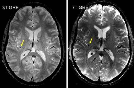
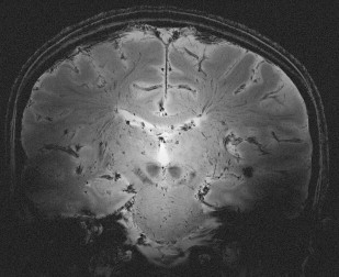
Relaxation measurements are also used to produce the so-called “relaxometry maps.” They provide valuable knowledge on the whole brain containing information on the microscopic structure of the brain. Relaxometry requires long acquisition times and that is why it has not been widely used in the clinical settings. Some techniques have been recently developed to accelerate their measurements and, as a consequence, to avail their benefits to the studies of neurodevelopment and diseases. At HF, high-resolution relaxation measurements enable MR to visualize very small structures in brain regions as voxel dimensions approache scales of microvessels and eventually individual cells. Gradient echo (GRE) images taken at HF reveal vast microvascular networks networks, as shown in Fig. 2 , which have never been seen before at lower fields. GRE is used for T2∗ measurements, whereas spin echo (SE) is required for T1 and T2 measurements. Recent measurements at 3.0 T using fast SE (FSE) have shown interesting patterns of T1 and T2 changes in brain tissues. As the SNR increases, relaxometry becomes more practical at 7.0 T and higher, which will provide valuable information about normal brain development. Similar work on disease progression would offer information about different mechanisms affecting the decay of transverse magnetization, which better characterizes the constituents of the voxel. This way, processes at the molecular level will translate into information that will enhance MR imaging specificity for the study of various diseases.
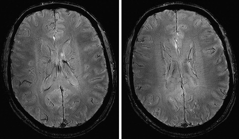
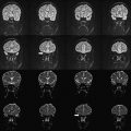
High resolution is one way of using the SNR currency at HF. As resolution increases, the number of protons (signal), noise spectrum, and contribution from partial volume effects decrease. Voxels contain the source of MR signal (ie, protons) and the source of noise (ie, everything else). Noise is also caused by several B 0 -independent mechanisms that are distinct from that generating the signal. These mechanisms include: (a) random fluctuation of μ, (b) thermal noise from the circuitry of the RF coil, (c) physiologic noise, and (d) and receiver bandwidth. Fluctuation of μ giving rise to nuclear spin noise spectra has been predicted theoretically and measured experimentally. Thermal noise is governed by (a) random electromagnetic signal generated in the body due to the movement of ions and other charged particles, (b) electronics noise generated by RF amplifiers, transmit and receive electronics, and RF coil structure, and (c) the receiver bandwidth. At HF, most of these contributions remain comparable to those of low-field MR imaging or increase linearly with B 0 . MR signal increases quadratically with B 0 . Increase in SNR is therefore in large part generated by increase in signal strength, which is caused by high B 0 . In addition to SNR, CNR determines the information content of MR images. Higher SNR and CNR are ideal for visualization of brain anatomy and pathophysiology. Although SNR is almost linearly dependent on B 0 , field dependence of CNR is more complicated. Resolution and CNR are the quantities that must be optimized by the choice of proper pulse sequence parameters. The high-resolution images in Fig. 3 show a comparison of 3.0 T and 7.0 T whole-brain acquisition. Although the higher resolution of 7.0 T represents the higher SNR, there is a distinct difference in WM/GM contrast between the two images. Experimental quantification of SNR and CNR with equivalent parameters corrected for field strength will elucidate the actual gain in HF compared to lower field strengths.