The development of ultrahigh field magnetic resonance (UHF-MR, B 0 ≥ 7 T, f ≥ 298 MHz) is moving forward at an amazing speed that is breaking through technical barriers almost as fast as they appear. UHF-MR has become an engine for innovation in experimental and clinical research. With nearly 40,000 magnetic resonance (MR) examinations already performed, the reasons for moving UHF-MR into clinical applications are more compelling than ever. The value of high field MR at 3 T has already proven itself many times over at lower field strengths; now 7 T has opened a window on tissues, organs, and (patho)physiologic processes that have been largely inaccessible in the past. The lion’s share of UHF-MR examinations today covers neuroscience applications where enabling technology has revealed new aspects of the anatomy, functions, and physiometabolic characteristics of the brain at an unparalleled quality.
The growing number of reports referring to cardiovascular applications is an inherent testament to the advancements of UHF-MR and documents the progress in imaging the heart and large vessels at 7 T. These technical and early feasibility studies in healthy subjects and patients respond to unsolved problems and unmet needs of today’s clinical cardiovascular magnetic resonance (CMR). These developments are fueled by the signal-to-noise ratio (SNR) advantage and the promise of enhanced relative spatial resolution (voxel per anatomy), and are enabled by novel MR technology. Transferring UHF-CMR into the clinic remains a challenge though. Arguably, the benefits of UHF-MR are sometimes offset by concomitant physics-related phenomena and by practical obstacles. These impediments include magnetic field inhomogeneities, off-resonance artifacts, dielectric effects, radiofrequency (RF) nonuniformities, localized tissue heating, and RF power deposition constraints. It is no surprise that these effects can make it a challenge to even compete with the capabilities of CMR at clinical field strengths of 1.5 T and 3 T. If these impediments can be overcome, the promises of UHF-CMR will open new avenues for MR-based myocardial tissue characterization and imaging of the myocardial macromorphology and micromorphology. The benefits of UHF-MR will catalyze explorations that go beyond conventional 1 H MR of the heart. This includes imaging and spectroscopy of 23 Na, 19 F, 31 P, 13 C, and other X nuclei to enable a better insight into inflammatory, metabolic, and (nano)molecular processes of the heart.
Realizing the progress and challenges of UHF-CMR, this chapter provides an overview of the state of the art of cardiac MR at 7 T. It discusses the clinical relevance of what has been already observed and what can be clearly foreseen. The chapter is devoted to surveying technical innovations, practical considerations, safety topics, frontier studies in healthy subjects, early clinical application in small patient cohorts, opportunities for discoveries, and future directions of UHF-CMR. At the moment some of these new concepts and applications are merely of proof-of-principle nature, but they are compelling enough to drive the field forward with the goal to advance the capabilities of cardiac imaging. As they are developed, the boundaries of MR physics, biomedical engineering, and biomedical sciences will be pushed in many ways, with the implications and potential uses feeding into basic cardiology research and clinical sciences.
In the sections that follow, encouraging developments into multiple channel RF concepts are reviewed. Advances in imaging methodology and progress in RF pulse design are discussed. Early applications for imaging of cardiac anatomy, cardiac chamber quantification, myocardial mapping, angiography of the large vessels, and real-time imaging of the heart are surveyed. Clinical opportunities for high spatial resolution MR and parametric tissue characterization (all being facilitated by the traits of UHF-MR) are also discussed. Physiometabolic CMR applications are explored, including sodium MR and phosphorus MR. Practical and safety considerations for cardiac MR in humans at 7 T are outlined. Current trends in CMR are considered, together with their clinical implications. A concluding section ventures a glance beyond the horizon and explores an even further step into the future, with something called extreme field magnetic resonance (EF-MR).
Enabling Technical Innovations for UHF-CMR
At ultrahigh fields the crux of the matter is that the RF wavelength in tissue λ becomes sufficiently short (λ myocardium ≈ 12 cm) versus the size of the upper torso. The heart, being a deep-lying organ surrounded by the lung within the comparatively large volume of the thorax, is a target region that is particularly susceptible to nonuniformities in the RF transmission field ( B 1 + ). These detrimental transmission field phenomena can cause shading, massive signal drop-off, or even signal void in the images, and hence bear the potential to offset the benefits of UHF-CMR because of nondiagnostic image quality. These constraints are not a surprise as it might appear at the first glance, because transmission field nonuniformities, although somewhat reduced, remain significant in CMR at 3 T. Further to the challenges imposed by B 1 + nonuniformities, magnetohydrodynamic effects severely disturb the electrocardiogram (ECG) commonly used for cardiac triggering at clinical field strengths. This challenge evoked the need for novel ancillary hardware that supports synchronization of MR data acquisition with cardiac activity.
To address the practical obstacles of UHF-CMR, technical innovations in RF antenna design have evolved in recent years. Novel pulse sequences for transmission field mapping and shaping as well as innovative RF pulse designs along with multichannel RF transmission were reported with the common goal to overcome the detrimental B 1 + phenomena at 7 T to enable cardiac imaging. Novel triggering techniques that are immune to electromagnetic fields have been established as an alternative to ECG. In this light, this section surveys enabling technical innovations tailored for UHF-CMR.
Enabling Radiofrequency Antenna Technology
A plethora of reports eloquently refer to the development of enabling RF technology tailored for CMR at 7 T. Research directions include local transceiver (TX/RX) arrays and multichannel transmission arrays in conjunction with multichannel local receiver arrays.
Multichannel RF coil designs tailored for UHF-CMR involve rigid, flexible, and modular configurations. The gestation process revealed a trend toward a larger number of transmit and receive elements to improve anatomic coverage and to advance the capabilities for transmission field shaping. Pioneering developments made good use of building blocks that include stripline elements, electrical dipoles, dielectric resonant antennas, and loop elements, with up to 32 independent elements.
Loop element-based CMR optimized 7 T transceiver configurations were reported for a 4-channel TX/RX ( Fig. 13.1A ), an 8-channel TX/RX ( Fig. 13.1B ), and a two-dimensional (2D) 16-channel TX/RX design ( Fig. 13.1C ). The 2D approach was extended to a more sophisticated modular 32-channel TX/RX array shown in Fig. 13.1D .

Various stripline element-based 7 T transceiver configurations were proposed for cardiac UHF-MR. In a pioneering 8-element transverse electromagnetic field (TEM) transceiver array design, each element was independently connected to a dedicated RF power amplifier. Other stripline array configurations run flexible designs consisting of a pair of 4 or 8 stripline elements. Another practical solution comprising an 8-channel stripline transceive array that uses sophisticated automated tuning with piezoelectric actuators was accomplished.
Electric dipole configurations have been shown to benefit MR of the upper torso and the heart at 7 T. Electric dipoles run the trait of a linearly polarized current pattern, where RF energy is directed perpendicular to the dipole along the Poynting vector to the subject, resulting in a symmetrical, rather uniform excitation field with increased depth penetration. Early implementations include straight dipole elements. The need for densely packed multichannel transceiver coil arrays tailored for UHF-CMR has inspired explorations into electric dipole configurations that comprise 8 or 16 bow-tie antenna building blocks, as shown in Fig. 13.1E and F . Each of the building blocks contains a bow-tie–shaped λ/2-dipole antenna immersed in D 2 O. This approach helps to shorten the effective antenna length.
Improvements in the compactness of dipole antenna arrays were also accomplished by incorporating lumped element inductors, by using fractionated dipoles, or by employing meander structures. The requirements of UHF-CMR along with ultimate intrinsic SNR and current pattern considerations has inspired alternative dipole antenna designs. One important development is bent electric dipoles. Other configurations include circular dipoles, which consist of a circular conductor with a feed point on one side and a gap on the other. Recently, proposed dipole antenna variants include folded dipoles or combinations of loop elements and dipole configuration. The snake antenna building block presents an alternative for the design of transmit arrays tailored for UHF-CMR.
Ultimate intrinsic signal-to-noise ratio (UISNR) considerations outlined that loop and dipole current patterns contribute equally to UISNR at 7 T. For field strengths of B 0 ≥ 9.4 T, current patterns are dominated by linear (dipole-type) current patterns, which provide motivation for shifting the weight to dipoles versus loop and stripline elements at 7 T and beyond.
Multichannel Radiofrequency Transmission
To translate the capabilities of multichannel RF coil configurations into practical value, advances in MR systems hardware abounded that help to mitigate signal variations across the heart and to address blood/myocardium contrast heterogeneity. State-of-the-art UHF-MR systems architecture supports multichannel transmit arrays to be driven in two modes, using (1) an array of independent-feeding RF power amplifiers (RFPA) with exquisite control of phase, amplitude, or even complete RF waveforms for all individual channels or (2) a single-feeding RFPA. For the single-feeding RFPA regime, the amplifier output is commonly split into fixed-intensity signals using RF power splitters. Phase adjustments for individual coil elements or groups of coil elements are accomplished with phase-shifting networks or coaxial cables. This setup provides a practical solution that can be made readily available for a large number of MR sites. In today’s research implementations, RFPAs with up to 16 kW peak power are used for the single-feeding RFPA mode. State-of-the-art multifeeding RFPA implementations support 8 to 16 RF amplifiers, each providing 1 to 2 kW adjustable RF output power. A multifeeding RFPA setup provides software-driven control over phase and amplitude by modulating the applied input signal. Moreover, it enables sophisticated parallel transmission of independent RF waveforms to every channel. On the journey to a broader range of UHF-CMR applications, it is beneficial if RF coil configurations provide flexibility which supports single-feeding as well as multiple-feeding RFPA regimes without major changes in cabling and other components. To this end, Fig. 13.2 shows an example of a 16-channel loop array tailored for UHF-CMR which is connected to a universal interface that supports the single-feeding and multifeeding RFPA modes. Transition between both modes can be accomplished in 5 seconds without the need for moving the patient or the patient table.

Progress in Pulse Sequence Development
Progress in UHF-CMR pulse sequence methodology includes two main categories: (1) novel approaches for transmission field mapping and (2) new technologies for transmission field shaping.
The knowledge of the spatial B 1 + distribution generated by RF coil arrays is pivotal for UHF-CMR to manage transmission fields across the heart, including magnetization preparation, signal excitation, and signal refocusing. B 1 + mapping approaches commonly used are mainly magnitude-based and are generally confined to the ratios or the fit of signal intensity images. For this purpose, sets of images are acquired using either two flip angles, identical flip angles but different repetition times (TR), variable flip angles, or signals from spin echoes and stimulated echoes, as well as signals from gradient echoes and stimulated echoes. It should be noted that B 1 + mapping is not a need limited to transceiver arrays tailored for 1 H UHF-MR but includes heteronuclear MR applications. For instance, B 1 + mapping has been applied to 23 Na MRI to support quantification of sodium tissue content.
Phase-based techniques present an alternative for B 1 + mapping, and were reported to be more accurate versus magnitude-based methods exploiting the low flip angle regime. Phase-based techniques commonly take advantage of a composite or off-resonance RF pulse to encode the spatial B 1 + information into the phase of the magnetization vector. Most phase-based methods, however, make use of nonselective pulses for volume excitation in conjunction with three-dimensional (3D) imaging schemes. This approach results in relatively long acquisition times that often exceed clinically acceptable breath-hold periods, along with a pronounced susceptibility for respiratory motion artifacts. Realizing these limitations, the feasibility of cardiac-gated, single-breath-hold B 1 + mapping has been demonstrated using a 2D phase-based Bloch-Siegert approach.
Notwithstanding the advances in B 1 + -mapping methodology, transmission field mapping of individual coil elements at 7 T has been primarily established for head imaging but remains a challenge for UHF-CMR because of depth penetration constraints and susceptibility artifacts. To cope with this challenge, B 1 + profiles are often derived from numerical electromagnetic field (EMF) simulations. For this purpose, the transmit phases for each coil element are adjusted using iterative algorithms to improve transmission field homogeneity in a region of interest encompassing the heart using a human voxel model. To ensure that the relative B 1 + distributions of the individual coil elements derived from the EMF simulations accord with reality, it is essential that EMF simulations are validated against MR measurements using phantoms filled with a dielectric liquid that resembles the dielectric properties of the target organ/tissue, as outlined in Fig. 13.3 .

Based upon a priori acquired B 1 + maps derived for all individual transmit channels of a coil array, B 1 + shimming can be used to reduce RF nonuniformities across the heart using the degrees of freedom of multichannel transmission to shape the transmission field for UHF-CMR.
Dynamic shimming is the forte of the multifeeding RFPA’s mode in conjunction with sophisticated pulse sequence developments, which support cascades of dynamic B 1 + shimming stages that balance the needs of preparation modules common in cardiac imaging such as inversion, fat suppression or blood suppression, pencil beam excitation across the diaphragm for navigator-gated respiratory motion compensation, and rapid imaging modules. Frontier CMR implementations of dynamic B 1 + shimming at 7 T include 2D CINE imaging, coronary MR angiography, and four-dimensional (4D) flow MR angiography of the entire aorta, which demonstrated improved excitation efficiency, increased SNR of myocardium and blood, and enhanced blood/myocardium contrast or helped to balance the B 1 + uniformity with B 1 + efficiency.
Multichannel transmission using spoke RF pulses presents a major breakthrough for pulse sequence developments tailored for UHF-CMR. A juxtaposition of the two-spoke approach with B 1 + shimming revealed an enhanced excitation fidelity or a reduced RF pulse energy for the two-spoke technique. This benefit holds the promise to be instrumental for a broader range of CMR applications, including uniform excitation for parametric mapping used for tissue characterization. The pulse designs used for two-spoke parallel transmission RF pulses make use of a single set of B 1 + / B 0 maps. This approach may not be suitable for subsequent scans acquired at another respiratory phase because of organ displacement, which might induce severe excitation profile and B 0 degradation. To address this issue, a tailored parallel transmission RF pulse design which is immune to respiration-induced B 1 + / B 0 variations has been recently proposed. Multiband spoke pulses afford simultaneous multislice acquisitions with enhanced flip angle homogeneity but minimal increase in integrated and peak RF power.
Ancillary Hardware Tailored for Ultrahigh Frenquency-Magnetic Resonance
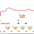
In current clinical MR practice, cardiac motion is commonly dealt with using electrocardiographic gating/triggering techniques to synchronize data acquisition with the cardiac cycle. If brought into a magnetic field, ECGs, being an electrical measurement, are corrupted by magnetohydrodynamic (MHD) effects. The MHD effect is pronounced during cardiac phases of systolic aortic flow, which results in a distortion of the S-T segment of the ECG. The susceptibility to EMF interference manifests itself in ECG waveform distortions already apparent in ECG traces acquired in clinical 1.5 T MR scanners. At ultrahigh fields the propensity of ECG recordings to MHD effects is pronounced. Artifacts in the ECG trace and severe T-wave elevation might be misinterpreted as R-waves, resulting in misdetection of cardiac activity or erroneous cardiac gating together with motion-corrupted image quality. Realizing the constraints of conventional ECG, an MR stethoscope has been proposed ( Fig. 13.4 ) for the pursuit of robust and safe clinical gated/triggered CMR. In contrast to ECG-triggering, the MR stethoscope employs acoustic instead of electrical signals. For cardiac gating/triggering, the first heart tone of the phonocardiogram, which marks the onset of the acoustic cardiac cycle, is selected. The phonocardiogram was reported to be immune to interferences with electromagnetic fields and to provide reliable and stable trigger information in UHF-CMR, as illustrated in Fig. 13.4 .

Safety of Human Cardiovascular Magnetic Resonance at 7 T
Radiofrequency Power Deposition
Radiofrequency pulses used in MR deposit RF power in tissue, which can be described by the specific absorption rate (SAR):
SAR=σ|E→|2ρ
At UHF-MR, the wavelength becomes sufficiently short versus the upper torso, which affects the ![]() field distribution inside the body and offsets some of the SAR predictions governed by :
field distribution inside the body and offsets some of the SAR predictions governed by :
SAR∝B12B02τRFmiTR
RF power deposition is substantially affected by the geometry of the upper torso, by positioning of the RF coil with respect to the torso and the heart, by the RF coil design, and by the number of RF transmission channels, as well as by the RF driving conditions. Here, EMF simulations are essential to provide an insight into the local SAR distribution. Recent simulation studies showed that using the merits of high RF frequencies for multichannel RF antenna array design, the relative SAR increase is even well below a SAR ~ B 0 dependency up to UHF-MR frequencies as high as 1 GHz (23.5 T) ( Fig. 13.5 ).

Although SAR is key for RF safety evaluations, temperature distribution—which is the cause of tissue damage based on RF heating—does not follow SAR in a straightforward manner. Thermoregulation and heat transfer inside the body (i.e., blood vessels) need to be considered while moving toward a more realistic scenario. Ongoing research focuses already on temperature modeling instead of SAR models, suggesting a thermal tissue damage threshold CEM43 known from thermal therapies. The thermal dose concept will be included in edition 4 of the IEC 60601-2-33 safety guidelines, which is expected to be finalized by 2018. Here, realistic thermal modeling based on electromagnetic field simulations and MR thermometry is essential to assess thermal distributions in vivo. These explorations will help to advance toward enhanced MR safety assessment for UHF-CMR. This development is expected to include a drive toward controlled E-field steering and targeted SAR reduction technologies in electrically conductive implants, catheters, and guide wires using parallel transmission to create excitations that induce minimal RF current in elongated conductors. An open-minded look reveals that UHF-CMR parallel transmission technology perhaps forms an enabling platform to advance interventional CMR applications at 7 T by using an MR antenna array to deliberately focus RF power and increase the temperature locally in a controlled way, denoted as thermal magnetic resonance. In this context, potential applications could include (1) targeted RF-guided drug release and image-guided monitoring, (2) localized contrast agent release and tracking, or (3) stem cell delivery to the myocardium afforded by local RF heating. In this context new developments of MR thermometry techniques and their validation will be crucial to MR safety and to advance the field of thermal therapies and thermal MR.
Radiofrequency-Induced Heating of Passive Conductive Devices
En route to broader clinical UHF-CMR studies, it is essential to gain a better insight into the interaction of passive conducting implants with RF fields. Considering an ever-increasing population of patients with a history of stent implantation, detailing the interaction of stents with RF fields is of profound relevance for the advancement of UHF-CMR. This is not an easy task because of the many RF coil and stent configurations available, yet becomes even more relevant when moving to many element transceiver arrays or even to large-volume coils covering major sections of the body.
At UHF-MR the RF wavelength ( λ ) in myocardial tissue and blood is sufficiently short ( λ approximately 12 cm) to induce resonance effects at λ /4 to λ /2 in coronary stents with a length of up to approximately 4 cm, a dimension common in clinical practice. EMF simulations and RF heating experiments showed that temperature increase due to coronary stents does not exceed baseline RF heating if IEC standards for local and global SAR limits are strictly obeyed. Although being very important, these early studies did not employ a setup that resembles a clinical scenario. The need for RF heating assessment at B 0 ≥ 7 T also prompted valuable research into RF-induced heating of metallic arterial stents. The conclusions drawn are valuable but constrained to the very specific experimental setup used.
Recognizing the opportunities for broader clinical UHF-CMR studies, RF-induced heating of coronary stents was examined at 7 T. For this purpose, EMF simulations were performed for a broad range of coronary stent configurations to detail electric fields and local SAR as a function of stent diameter, stent length, stent position with respect to the RF transmission source, and stent orientation versus the E-field. To translate these results to arbitrary coronary stent geometries, arbitrary stent positions, and arbitrary RF coil configurations, a transfer function for the assessment of EM fields induced in coronary stents was proposed. SAR 1g induced by a stent (SAR 1g stent ) can be described by:
max(SAR1gstent)=f(diameter,length,orientation)⋅SAR1gbaseline

The transfer function provides a fast way to estimate induced stent SAR levels. EMF simulations performed with a stent integrated in a human voxel model prove to be very time consuming. This is a particular practical obstacle if many-element RF TX/RX arrays and a set of phase settings mimicking B 1 + shimming or other parallel transmit applications are included. Benchmarking the analytical approach versus EMF simulations showed a good conservative estimation of induced SAR 1g peak levels. A practical example is shown in Fig. 13.6 using an 8-channel bow-tie antenna RF coil array optimized for CMR at 7 T (see Fig. 13.1E ). EMF simulations including the stent consumed more than 2 hours central processing unit (CPU) and graphics processing unit (GPU) time per phase setting (not including RF shim field combining and SAR calculations) while the analytical approach can be calculated in real time. This example underscores the value of the proposed analytical approach based upon a transfer function for obeying regulatory RF power limits. The approach of using a transfer function is conceptually translatable to other implant configurations, which is in particular suitable for short implants (≤λ tissue /3) where the influence of the phase distribution of the RF transmit field is negligible. Furthermore, it can be conveniently incorporated into state-of-the art SAR prediction concepts to provide SAR estimations induced by coronary stents and other conductive implants for arbitrary RF pulses used for transmission field shimming or parallel transmission. To generalize, this approach provides a novel metric or design criteria for RF coils: for example, to design RF coils (1) with low SAR levels in the vicinity of the stent or (2) with SAR levels during the presence of the stent which do not exceed SAR levels without the presence of the stent. The transfer function approach should not end at SAR estimation, but should move toward temperature or CEM43 estimations. In particular, for short implants like coronary stents, maximum induced SAR levels in the implant are much more restrictive to the allowed input power than maximum temperature or CEM43 values would be. It was shown that even though maximum induced local SAR at the stent tip was by a factor >2 higher than in surface regions, the eventual temperature after 6 minutes of RF heating was by >6°C lower at the stent tip region. This temperature saturation effect at the stent tip originates from a strong temperature gradient toward colder tissue regions at the stent center and is even more pronounced by physiologic parameters such as blood flow in the stented vessel. These findings are heartening; they will accelerate further research on safety assessment of coronary stents and other implants common in clinical practice and will help to relax current UHF-CMR limitations.
Stay updated, free articles. Join our Telegram channel

Full access? Get Clinical Tree


