Fig. 4.1
Operative findings of an anterior communicating artery (ACoA) aneurysm, a left internal carotid artery (ICA)–posterior communicating artery (PCoA) aneurysm, and a right ICA–PCoA aneurysm. (a) Operative view through the microscope of an ACoA aneurysm via the interhemispheric approach. (b) ICG-VAG image during ACoA aneurysm surgery via the interhemispheric approach. Fine perforating arteries from the anterior cerebral artery (ACA) (arrows), as well as Heubner’s arteries (arrowheads), can be observed. (c) Operative view through the microscope of a left ICA–PCoA aneurysm via the left pterional approach. (d) ICG-VAG image during left ICA–PCoA aneurysm surgery via the left pterional approach. Fine perforating arteries from the PCoA (arrow) and anterior choroidal artery (arrowhead) can be observed. (e) Operative view through the microscope of a right ICA–PCoA aneurysm via the right pterional approach. (f): ICG-VAG image shows poor blood flow at the sclerotic portion of the ICA (arrowheads) and good blood flow at the aneurysm and ICA with a normal wall (arrows)
In addition to these points, change of flow velocity during ICG-VAG should be mentioned. One case showed decreased fluorescence intensity at the parent artery (internal carotid artery) proximal to the aneurysm after clipping (Fig. 4.2b, c). The flow velocity of ICG fluorescence at this artery and the ophthalmic artery became normal after clip reapplication (Fig. 4.2d, e).
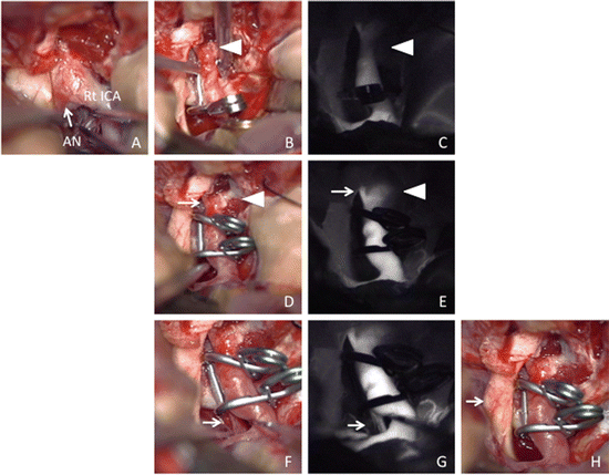

Fig. 4.2
Operative findings of right ICA–ophthalmic artery (OphA) aneurysm surgery via the right pterional approach.
(a) Operative view through the microscope shows an aneurysm located under the right optic nerve (arrow). (b) Operative view through the microscope after first clipping aneurysm using one fenestrated clip is suspected the stenosis of ICA (arrowhead). (c) ICG-VAG image after first clipping aneurysm shows decreased ICG fluorescence intensity in the ICA proximal to the aneurysm (arrowhead) due to stenosis of this artery. (d) Operative view through the microscope after reapplication using two fenestrated clips to reduce ICA stenosis (arrowhead). (e) ICG-VAG image after reapplication shows good intensity of ICG fluorescence in ICA (arrowhead) and OphA (arrow). (f) Operative view through the microscope after clip reapplication shows preservation of perforating arteries (arrow). (g) ICG-VAG image shows good intensity of ICG fluorescence in the perforating arteries from PCoA (arrow). (h) Operative view through the microscope after puncture of aneurysm shows decompression of optic nerve (arrow) by aneurysm
Furthermore, ICG fluorescence remains observed in the vessels (especially in the veins); an interval more than 5 min may usually be necessary for repeated examinations. When the clip was reapplied in a short time after a first incomplete clipping procedure, ICG fluorescence remained in the aneurysm. In this situation, it is important to observe whether intensity of ICG fluorescence in the aneurysm increases for 3 min after injection. The duration of examination needs to be considered, because it has been reported that brain temperature increased during observation using ICG-VAG [27]. The Zeiss microscope system stops automatically after 5 min of usage.
Since ICG-VAG is easy and safe for neurosurgical procedures with a microscope, it has become the routine examination for clipping cerebral aneurysms. However, surgical complications have been reported even though ICG-VAG was done [23, 24, 26]. Dashti et al. reported that a neck remnant was recognized in 6 % of surgeries, especially for anterior communicating artery aneurysms, and parent artery stenosis and occlusion of the perforating artery were observed in 6 % of surgeries, especially for middle cerebral artery aneurysms [28]. Roessler et al. reported that the postoperative angiography demonstrated unexpected residual aneurysms in 9.1 % of successful ICG-VAG-guided clip applications [29]. In the present study, perforating artery infarction was observed in 5 cases with a middle cerebral artery aneurysm and one case with anterior communicating artery aneurysm. Among them, one case showed transient hemiparesis, and others were asymptomatic fortunately. Because a blind field such as behind the clip may exist even with ICG-VAG, Doppler ultrasound, endoscopic observation, and electrophysiological monitoring should be added for safe and precise clipping surgery. Recently, the association of endoscopic ICG-VAG with microscopic ICG-VAG allowed a better observation of perforating arteries located deeply [30, 31].
4.3.2 ICG-VAG for Bypass Surgery
Extracranial (EC)–intracranial (IC) bypass surgery is performed for patients with hemodynamic atherosclerotic vascular lesion or moyamoya disease and patients with large or complex cerebral aneurysms that require proximal artery occlusion or trapping aneurysm. The intraoperative assessment of graft patency is essential for successful EC–IC bypass surgery. The usefulness of ICG-VAG for flow evaluation in bypass surgery has been reported [6, 32–34]. Woitzik et al. reported that this examination was useful for recognition of patency of anastomosis by comparing the findings of ICG-VAG with those of postoperative computed tomography angiography [6].
We performed ICG-VAG for 14 cases involving superficial temporal artery (STA) and middle cerebral artery (MCA) anastomosis. After the anastomosis, ICG-VAG was done to observe the patency of the anastomosis and blood flow from the STA to the anastomosed MCA, following Doppler ultrasound examination. The patency of the anastomosis observed on ICG-VAG was recognized also on postoperative cerebral angiography or computed tomography angiography. Although patency of the anastomosis can be recognized using Doppler ultrasound, ICG-VAG could show blood flow itself.
ICG-VAG demonstrated the flow from the STA 20 s after ICG injection (Fig. 4.3b), and the vessels of the brain surface were recognized 40 s later (Fig. 4.3c). In this case, the fine arterial network characteristic of moyamoya disease was observed clearly. Furthermore, in ICG-VAG for bypass surgery, cleaning the operative field is important, and surgicel applied on the anastomosed region for hemostasis is mentioned. We usually remove this surgicel before ICG-VAG, since a small amount of surgicel disturbs observation of ICG fluorescence at the anastomotic region.
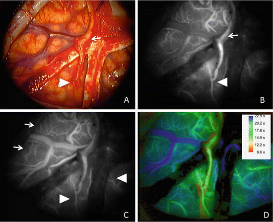

Fig. 4.3
Operative findings during bypass surgery for moyamoya disease.
(a) Operative view through the microscope after anastomosis of the left superficial temporal artery (STA) (arrow) and middle cerebral artery. (b) Image 20 s after ICG injection shows patency of the anastomosed portion (arrowhead) from STA (arrow). (c) Image 40 s after ICG injection shows blood flow from the STA (arrowheads) and from the collateral circulation (arrows). (d) Image by FLOW 800 shows the timing of fluorescence flow as a different color. The number means the time after the start of recording
Recently, a microscope-integrated software tool for instant color-coded visualization and analysis of the temporal distribution dynamics of the fluorescence ICG (FLOW 800) was created. Prinz et al. evaluated usefulness of FLOW 800 in 30 cases undergoing bypass surgery and concluded that FLOW 800 may detect procedure-related hemodynamic changes within the microcirculation and macrocirculation but should not be used as a stand-alone tool for quantitative flow assessment [34]. Figure 4.3d shows our case using FLOW 800. The fast-flow area (area supplied by the bypass) was shown as yellow green, the medium speed flow area (area supplied by an intracerebral artery) was shown as light blue, and the show speed area (veins) was shown as blue.
4.3.3 ICG-VAG for Carotid Endarterectomy (CEA)
CEA is a safe and durable treatment that has been shown to prevent ipsilateral stroke. This procedure should be performed without cerebral embolism or residual plaque. The usefulness and limitations of ICG-VAG for CEA have been reported, and authors emphasized the importance of usage of a mixture of 12.5 mg of ICG and 5 ml of distilled water as a single injection to visualize ICA blood stream [35, 36].
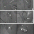
We performed ICG-VAG for CEA in 35 surgeries. In early 10 surgeries, we injected 5 mg of ICG for one examination, and it was difficult to recognize the usefulness of ICG-VAG for this surgery. The reasons for this lack of usefulness were the thick wall of the carotid artery, sclerotic changes, calcified regions, vasa vasorum of the carotid artery, and difficulty of cleaning the operative field due to oozing blood. In later 25 surgeries, we injected 12.5 mg of ICG for one examination. Before arteriotomy, blood flow within the ICA was rapidly visualized with a latency of 10–20 s following ICG injection, followed by subsequent contrast enhancement of the venous system. Definitive lack of fluorescence was observed in some cases (Fig. 4.4a, b), although severe calcification of the plaque did not allow determination of the exact location of the stenosis. At the distal end, ICA patency was seen with no stenosis in many cases. At the end of surgery, the ICA was demonstrated to be patent by homogeneous enhancement, although the cotton and blood disturbed observation of ICG fluorescence (Fig. 4.4c, d). Image by FLOW 800 showed the time–intensity curves at the plotted areas, and it was useful to recognize the flow improvement after CEA (Fig. 4.4e, f).
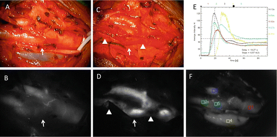

Fig. 4.4
Operative findings of carotid endarterectomy (CEA) for right carotid stenosis. (a) Operative views through the microscope before arteriotomy. (b) ICG-VAG image before the arteriotomy shows poor blood flow at the carotid bifurcation where the plaque is located (arrow). (c) Operative views through the microscope after CEA. (d) ICG-VAG image after CEA shows good intensity of ICG fluorescence at the carotid bifurcation (arrow), but the cotton and the blood obscured the fluorescence intensity in the artery (arrowheads). (e, f) Flow 800 analysis showing the time–intensity curves at the plotted areas demonstrates the improvement of blood flow at the area plaque located (plotted areas 2, green; 5, light blue)
4.3.4 ICG-VAG for Vascular Malformations
In surgery of arteriovenous malformations (AVMs), it is crucial to recognize the feeding arteries, nidus, and draining veins. ICG-VAG provides information about vessel architecture and patency by the difference in the timing of enhancement of these structures. The usefulness and limitations of ICG-VAG for AVM surgery have been reported [37–41]. This technique is useful for early identification of AVM arteries and veins, helping the surgeon to formulate and modify the operative strategy for attacking these formidable lesions. The information, which is provided within seconds of an injection, can potentially make surgery safer and faster, giving the surgeon more confidence in resecting AVM arteries while preserving draining veins. The major limitation of ICG-VAG is that it captures only what is visible within the field of the microscope. Consequently, ICG is frequently of limited use for deep-seated AVMs such as thalamic lesion. Although intraoperative digital subtraction angiography (DSA) remains the “gold standard” for evaluation of vascular flow in AVM surgery, ICG-VAG may decrease the need to perform DSA multiple times.
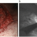
We performed ICG-VAG for cerebral AVMs in 2 surgeries. In the cryptic AVM hidden in the occipital sulcus, recognition of draining vein using ICG-VAG was useful to confirm the location of nidus (Fig. 4.5b, c, d). After removal of AVM (Fig. 4.5e), the draining vein was not shown on ICG-VAG image (Fig. 4.5f). These findings were confirmed using intraoperative DSA (Fig. 4.5a, g).
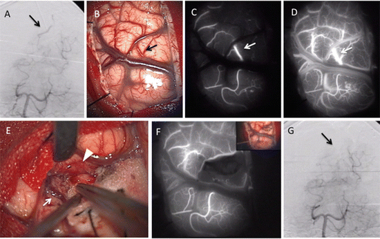

Fig. 4.5
Operative findings of arteriovenous malformation (AVM) hidden in the right occipital lobe sulcus. (a) Intraoperative vertebral angiography (VAG) shows early venous filling (arrow). (b) Operative view through microscope shows a draining vein as a red vein (arrow) at the right occipital cortex before removal. (c, d) ICG-VAG images before removal show early appearance of ICG fluorescence in this vessel (arrow). (e) Operative view through the microscope shows a feeder (arrowhead) and a drainer (arrow). (f) After removal, ICG-VAG image shows no early venous enhancement of ICG. (g) Intraoperative VAG shows disappearance of early venous filling recognized before surgery (arrow)
Faber et al. reported the usefulness of FLOW 800 in two patients with frontal or temporal AVMs [37]. They concluded that color-coded analytical ICG-VAG with FLOW 800 enabled intraoperative real-time analysis of arterial and venous vessel architecture and might increase the efficacy and safety of neurovascular surgery in a selected subset of superficial AVMs.
4.3.5 ICG-VAG for Spinal Arteriovenous Fistula (AVF)
In surgical treatment of spinal AVF, identification and complete interruption of fistulae are essential, but not always obvious during surgery. The reported advantages of ICG-VAG for this surgery are the identification of the fistulous site and confirmation of its obliteration during surgery [42–44]. The reported disadvantages are the increase of operating time and the limited visualization to the operating field with a need to fully expose the fistula [43, 44]. Intra-arterial ICG-VAG may localize the exact fistula portion by minimizing the influence of normal arterial vasculature simultaneously enhanced by conventional peripheral venous ICG injection [44].
4.3.6 ICG-VAG for Cavernous Malformations (CMs)
The usefulness of ICG-VAG for removing CMs has been reported [45, 46]. Murakami et al. reported that ICG-VAG could directly visualize cerebral CMs and orbital cavernous angiomas, and it demonstrated slow and low perfusion within the lesions. They concluded that, by understanding the characteristic features of flow dynamics, the intraoperative ICG-VAG provides useful information for microsurgical resection of cerebral CMs [45]. Endo et al. examined the potential utility of ICG-VAG for the surgical treatment of intramedullary CMs in 8 cases. They concluded that ICG-VAG provided useful information with regard to the detection of lesion margins by demonstrating intramedullary CMs as avascular areas. In cases with venous anomalies, ICG-VAG contributed to safe and complete removal of the lesions by visualizing the venous structure. In extramedullary CMs, ICG-VAG demonstrated the characteristics of slow blood flow within cavernous malformations [46].
On the other hand, Niemela et al. commented that its clinical value for microsurgery of brain CM is very limited, since ICG-VAG does not help in finding the lesion. Furthermore, the extent of removal of a CM cannot by reliably estimated using ICG-VAG [47].
4.3.7 ICG-VAG for Tumors in the Central Nervous System
For tumor surgeries, ICG-VAG was used in the identification of tumor vessels, normal brain parenchyma vessels, bridging veins, and tumor margin [48–53].
Hemangioblastomas remain a surgical challenge due to their AVM-like vascular structure. Identification of the feeding arteries and draining veins, as well as tumor location, is crucial for en bloc tumor resection and cure during surgery. ICG-VAG could provide dynamic images of blood flow in the tumor and its related vessels under surgical view. The usefulness of ICG-VAG for resection of hemangioblastomas has been reported previously [48–50]. Tamura et al. reported the usefulness of this method in nine surgeries for patients with hemangioblastomas of the cerebellum, medulla oblongata, or spinal cord. They concluded that ICG-VAG was a safe and easy modality for confirming the vascular flow patterns in hemangioblastomas. In addition, ICG-VAG provided useful information for intracystic small lesions or lesions concealed under thin brain tissue in order to accomplish total resection of these tumors [48]. Hao et al. reported the limitations in their experience of 7 surgeries for spinal hemangioblastomas; one was partially removed, though 6 tumors were completely removed. The partially removed tumor was located deep in the spinal cord parenchyma, which did not take up fluorescent dye and was, therefore, not visualized by ICG-VAG. They concluded that the benefits of this technique might be limited for deep tumors and ventral tumors [50].
Stay updated, free articles. Join our Telegram channel

Full access? Get Clinical Tree


