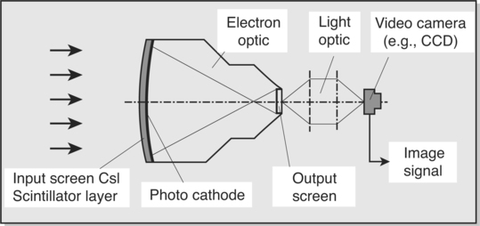
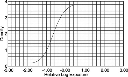
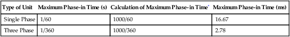
Image Capture—Analog and Digital

CHAPTER 2


Image Capture—Analog and Digital


During special procedures, as with conventional radiography, there must be a system to capture the images produced during the studies, store the images for processing, and display the images during the procedure as well as providing a permanent copy for archiving and future analysis. The images must also be portable so that they can be viewed by several different medical specialists for diagnosis.


In conventional radiography, the image is recorded on x-ray film, which is then processed, viewed, and filed to provide permanent storage and communication capabilities. Generally speaking, the images produced by conventional radiographic methods are “passive” and are not meant to demonstrate motion or changes in the anatomic part during the procedure. These images are usually archived on film and can be physically transported for viewing at remote locations. Their main disadvantage is that the films can degrade over time and can also be lost or damaged.


Conventional fluoroscopy can capture the images on x-ray film, cine film, or magnetic media while displaying the images of the study on a display monitor for viewing in real time during the procedure. The advantages of this system are that changes can be recorded as they happen, analyzed during the procedure, and also kept for future use. The images produced by conventional fluoroscopy also share the disadvantages of those produced by conventional radiography.


In general, advanced procedures are dynamic studies. They are designed to demonstrate physiologic sequences, such as the passage of a bolus of contrast medium through a portion of the vascular system. These sequences last only a few seconds, and if any abnormality is present, it might be visible for only a fraction of a second. The images have been produced by means of serial exposures which are captured, stored, processed, and presented for viewing. Several types of systems have been used to archive these images—conventional film/screen images from rapid serial changers, storage on magnetic recording devices, laser optical devices (videodisc), large-format serial spot filming devices, cinefluorography, and digital image storage devices.


Radiographic systems have been designed with one or more of these recording media incorporated into the design. Analog imaging systems were the systems of choice for many institutions, primarily because of the expense of digital systems. In recent years, however, as older equipment is being replaced, digital imaging systems are becoming more prevalent, especially in the advanced procedure suites. The use of image sharing systems such as PACS (picture archiving and communication systems) is also becoming commonplace in the imaging department. Older analog systems are giving way to the newer CR (computed radiography) and DR (digital radiography) systems.


A historical review of some of the analog image capture devices that have been used in the past and present is presented. It is anticipated that within the next 5 years digital radiographic systems and flat panel technology will replace these systems in the advanced radiography suite.


DIRECT IMAGING SYSTEMS


Rapid Serial Film Changers—An Historical Perspective


As their name implies, rapid serial film changers were used to record a sequential series of images that occurred during the special procedure. Images that were captured via analog techniques were recorded on radiographic film and were processed in the usual manner to provide the finished image. These types of systems produced a series of static images representing the changes that developed during the procedure. The images produced represented glimpses of the process over a period of time. The disadvantage to this type of system was that the dynamic nature of the pathologic or physiologic process could not be demonstrated.


Rapid serial changers were produced by a variety of manufacturers. However, all systems had several elements in common. A short discussion of the basic operational features of rapid serial changers is presented primarily from the historical point of view.


Rapid serial film changers were produced in one of two types—those that transported cut film and those that transported roll film.


Roll Film Changers


Roll film changers are obsolete and are considered here only in a historical perspective. The operation of a rapid serial roll film changer can be compared with that of a movie projector. Roll film changers had four major parts: (1) changer and mounting stand; (2) supply magazine; (3) receiving magazine; and (4) program selector.


Cut Film Changers


Rapid serial cut film changers rapidly transported single sheets of film of a specific size. The 14- × 14-in (35.6- × 35.6-cm) and the 10- × 12-in (25- × 30-cm) sizes were most often used. These units were available as single-plane changers; however, two units on different mounting stands were often combined for biplane operation.


The cut film changer was similar to a roll film changer in that it also contained four major components: (1) changer and mounting stand assembly; (2) supply magazine; (3) receiving cassette; and (4) program selector.


image Film changer and mounting stand assembly. The cut film changer, unlike the roll film changer, transported film by means of roller systems. This type of changer was similar to an automatic processor in some respects.


image Mounting stand. The two basic mounting stands were made for horizontal or vertical changers. These changers were also attached to the image intensifier on the C-arm or as built-in models in a radiographic table. When the units were attached to a C-arm, conversion from fluoroscopy to serial radiography was easily accomplished in a minimal amount of time.


image Supply magazine. The supply, or loading, magazine was a stainless-steel box that was easily carried to and from the darkroom.


image Receiving cassette. The receiving cassette, a stainless-steel container with a light-tight lid, served as a carrying case for the exposed films that were sent through the changer.


image Program selector The program selectors for both roll and cut film changers operated in a similar manner. The display panel listed all the information necessary for a specific program, even listing errors that needed to be corrected before beginning the procedure.


An automatic cut film changer was also available for peripheral angiography, with an exposure frequency of two exposures per second. An interesting feature of this unit was the central radio transparent opening, through which fluoroscopy could be used to position the patient and place the catheter. Its operation was similar to that of the cut film changer previously described.


Basic Operational Considerations


All of the rapid serial changers discussed operated in a similar manner (Fig. 2-1). They moved the imaging material into place for the exposure and then removed it to a storage location. In other words, with all rapid serial changers there was a period of time during which the film or cassette was in motion (transport time) and a period of time during which no motion occurred and the film was in position for the exposure (stationary period). The radiograph had to be produced during the stationary period. The stationary period for each of the types of rapid serial changers was different; however, it was usually less than 50% of the total film cycle time (transport time + stationary period). Certain inherent electronic delays prevented the entire stationary period from being used to make the exposure. These were the zero time and phase-in time.


The actual amount of phase-in time varied with each exposure and could not be predetermined. However, the maximum exposure time that could be used for a particular system was calculated by deducting the greatest phase-in time delay from the stationary period. Table 2-1 illustrates the maximum phase-in time delays for single-phase and three-phase units.


Biplane Radiography


A discussion of image capture would not be complete without consideration of biplane operation. The term biplane as applied to rapid sequence radiography is defined as simultaneous radiography in two planes (Fig. 2-2).


When rapid sequence changers are used for biplane radiography, certain technical difficulties arise. The most important factor, scatter, necessitates the use of special crossed grids in the vertical changer. This grid should absorb the scatter radiation produced in a biplane setup that strikes the vertical changer. This causes an increase in the density of the film in the horizontal changer. These factors should be considered when choosing the technical parameters for biplane operation. If single-plane study is required on the same patient, an adjustment in technique will be necessary to compensate for this effect.


We can see, therefore, that during biplane studies, it is necessary to use different exposure factors in each of the two planes. This is possible only if the x-ray tubes are supplied with separate generators, thus providing flexibility of technical factors for each tube. If, however, the x-ray tubes are connected in parallel on one generator, the selection of these factors will be severely compromised, and technical adjustments for the increased scatter radiation to one plane will be limited.


INDIRECT IMAGING SYSTEMS


Rapid serial radiographic systems produce the image through the direct interaction of the x-radiation with the screen/film system. Indirect imaging systems, however, record the image using the information produced at the output phosphor of an image intensification device. Indirect imaging systems include videotape recorders, videodisc recorders, digital recording systems, serial spot filming devices, and cinefluorographic systems. Videotape, videodisc, and digital recording systems use an electronic signal to produce the image, whereas the serial spot filming devices and cinefluorographic units (photofluorographic systems) capture the image directly from the output phosphor of the image intensifier. Digital imaging systems are replacing spot film devices and cinefluorography systems. However, the devices used in the indirect imaging systems discussed in this chapter are still in use and in some cases are still being sold as generic add-ins by some retailers. A brief discussion of their operation is included.


Knowledge of the operation of the image intensification system is essential to understanding the principles of the indirect imaging recording devices. Several changes have been made in image intensification design to improve the quality of the images produced; however, the basic process and materials have not changed. A brief review of the principles of image intensification follows.


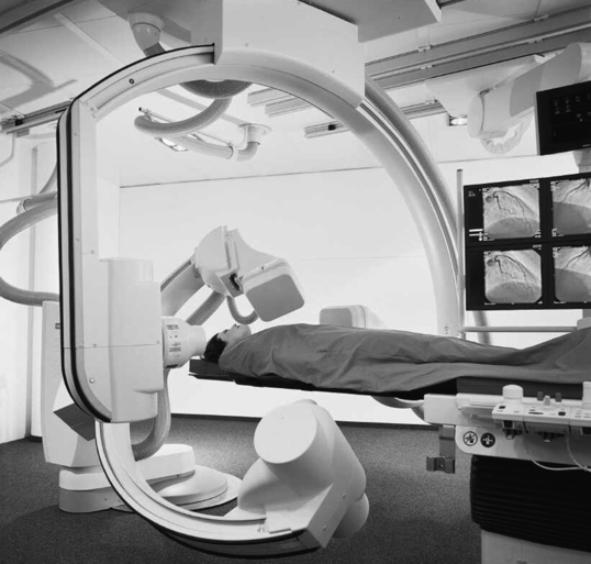
Image Intensification


An image intensifier (II) is used to increase the brightness of the image. This is accomplished with the II tube (Fig. 2-3). The input side of the II tube is coated with a phosphor layer, usually cesium iodide, that produces the image as a direct result of the action of the remnant radiation. Photoemissive material is coated on the substrate opposite the phosphor layer; this material converts the visible light image into an electron image. The electrons making up the image are accelerated across the II tube by an electron lens system and focused to strike the output side of the tube.


The output side of the II tube is also coated with a phosphor, which converts the electron image to a smaller, corresponding light image. The image at the output side of the II tube is brighter. This results from the process of reducing the size of the image and the acceleration of the electrons.


A television camera, either high resolution charge-coupled device (CCD) video camera or pickup tube, is attached directly to the output side of the II tube via a special lens system or fiberoptic disc. The CCD is an integrated light-sensitive circuit (chip) that can store and display the data of an image. The image is produced as separate picture elements (pixels), which exhibit electrical charges of varying intensities. The intensities are related to a corresponding “color” of the visible spectrum. Charge-coupled devices are found in digital cameras. The advantage to this type of system is that images can be produced in low light situations without the loss of resolution. The images produced can be transmitted to a television monitor as well as other types of recording devices. The use of an image distribution device will also allow the attachment of a serial spot filming device, a cinefluorographic unit, or both, to the system.


IMAGE OUTPUT


DICOM Standard


The data collected through the image capture systems can be made available globally and should be readily accessible. Originally, there were several different proprietary standards, and the information could not be shared by the systems that were in use. This limited the value of the data to a specific institution and its diagnostic imaging department. In order to accomplish global sharing of information, there was a need for some type of standard in medical imaging for the archiving and communications of medical images and information. The need also existed for a common database that could be accessed and searched easily.


The American College of Radiology (ACR) and the National Electronics Manufacturers Association (NEMA) recognized this with the advent of computed tomography and formed a consortium to develop a standard for file formats that could be understood by equipment and systems manufactured by different companies. The format was termed the Digital Imaging and Communications in Medicine Standard, or DICOM. In 1983 the ACR and NEMA formulated a standard1 that would:


The original standard was published in 1985, and it proposed a specific type of interface, special software commands, and consistent data formats. Since the original standard was published, it has undergone several revisions that include several enhancements to the original version. NEMA views the DICOM standard as an evolving set of guidelines. The DICOM standard is directed at providing a platform for the interoperability of various devices and systems primarily in the area of diagnostic medical imaging. The specific guidelines and specifications of the DICOM standard are beyond the scope of this text. They are available from the National Electrical Manufacturers Association and can be found on their website—(http://www.nema.org).


Previously, magnetic videodisc systems were used to indirectly record the images produced during the study using a rigid disc coated with an emulsion similar to magnetic tape. These have been replaced by recordable CD-ROM devices that use the CD Medical DICOM 3 international format. An example of this type of system is the Siemens ACOM, an archiving and review station with accompanying ACOM.PC software (Fig. 2-4). The computer system is a relatively small computer system, which houses the DICOM software. The information from this system can be sent to a PACS workstation, or the images can be archived either on the hard drive or on CD-ROM.


Hard Copy Image Output


Hard copy images produced in the state of the art digital equipment results from the conversion of a digital image into its analog counterpart. This process is accomplished using a digital to analog conversion (DAC) system and usually a laser or dye sublimation printer.


Older systems used film to capture the image, and the cameras were usually attached to the image intensifiers (II). The image capture systems discussed next may be used in certain areas and warrant a brief discussion of the principles of their operation.


Photofluorographic Systems


This category includes the serial spot filming device and the cinefluorographic camera. It should be noted that the spot film devices are not necessary in the current “state of the art” equipment, digital systems. These components were attached to the II by an image distribution unit. This unit contains a beam-splitting mirror for diverting the optical image onto the lens of the photofluorographic device. The serial spot filming and cinefluorographic camera record the image from the output phosphor of the II in the same way; that is, the light image from the output phosphor creates the image on the photofluorographic film.


Serial Spot Film Cameras.

This type of unit is also called a large-format, spot film, or rapid sequence camera. Such cameras may be referred to by the size of film they use. The current film size formats were 70, 90, 100, and 105 mm; the most commonly used film formats were 100 and 105 mm. Spot film cameras are capable of recording from 1 to 12 pictures (frames) per second (fps) and can use either roll or cut film depending on the manufacturer and model.


The serial spot filming devices do not contain a shutter. The image is produced on the II by using a pulsed x-ray beam. When the beam is on, an image is recorded; when the beam is off, no image is produced on the output phosphor and therefore no image is recorded in the camera.


The major difference between the photofluorographic and serial spot film systems is the finished product. The serial spot filming units produce images that are separated by a specific time interval and demonstrate the changes in the anatomy and pathology as a sequence of static events. These are usually cut from the roll of film and are viewed in sequential order.


Cinefluorographic Systems.

The cine camera is similar in construction to a movie camera. The device contains (1) lens system; (2) supply spool; (3) motor-driven film transport mechanism; (4) take-up spool; and (5) rotating shutter. Film sizes for the cine camera are 16 and 35 mm. The larger format is more popular because it produces a better-quality image.


The operation of the cine camera is also similar to that of a home movie camera. The film is passed in front of an aperture (hole) in synchronization with the shutter system; therefore, the film is in motion when the shutter is closed and stationary when the shutter is open. The image on the output phosphor of the II tube is produced by a pulsed x-ray beam. The pulsed format reduces the radiation dose to the patient, decreases the heat loading of the x-ray tube, and helps reduce motion artifacts, allowing very short exposure times.


The motor used to drive the transport mechanism is capable of varying speed settings. The speed of the motor will govern the number of frames per second that are exposed. The range of frames per second can be from 8 to 200 depending on the film size used. Cinefluorography is usually accomplished at frame rates in excess of 16 fps to produce the effect of motion when the final images of the study are projected for viewing.


Cineradiographic film must be properly matched with the emission spectrum of the output phosphor of the II. The type of film used is either orthochromatic (yellow or green-blue sensitive) or panchromatic (orange, red, green, yellow, and violet sensitive). Film processing can be accomplished with a specialized processor that can handle film sizes ranging from 35 to 105 mm.


Cinefluorographic units are used during cardiac catheterization to record the sequences in the coronary vasculature. They can be used in a single-plane setup or, if a C-arm is used, as a biplane system.


Multiformat Cameras.

The systems discussed above all relied upon the photography of an image either on an intensifying screen, cathode ray tube (CRT), television, or oscilloscope. In all of the cases the image was captured, stored, and displayed or converted into a hard copy image. The quality of the image produced depended upon the components of the image recording system. This is a well-known principle in general radiography. The image is degraded by a variety of factors in the system. Among them were the CRT brightness, phosphor graininess, distortion, and artifacts as well as the optical systems themselves. The image output devices discussed earlier produced a single image on a single frame or film. The desire to place more images on a single film as in CT and ultrasound studies led to the development of the multiformat camera.


Initial systems used various methods to produce the images. These included motorized optics and multiple lenses to produce the images. By varying the distances of the lenses and the film, it became possible to change the size of the images produced. Many advances were introduced to improve on the quality of the output produced by these cameras. These included better optics, the use of flat screen monitors. and improved phosphors. Eastman Kodak produces several types of single-emulsion radiographic film for use with the multiformat camera. Figure 2-5 illustrates the sensitometric properties of three of Eastman Kodak’s multiformat films. Note that there is a suitable variety of film speeds and average gradients among the films. These are all sensitive to the higher wavelength green light and are compatible with most CRT monitors. These cameras are still employed in many institutions and find their greatest use in ultrasound and nuclear medicine.


LASER IMAGING SYSTEMS


Digital images are easily stored and shared through the PACS; however, there is still a need in all of the modalities using digital imaging for hard copy images. This is accomplished through the use of laser imaging systems. Laser imagers record the digital image on special radiographic film. A special infrared single-emulsion film is scanned by the laser, which then transfers the digitized densities to the film emulsion as various shades of gray. In current 12-bit systems it is possible to produce 4096 shades of gray. This allows the laser printing system to reproduce the image without the loss of information or the introduction of artifacts.


Laser imaging systems can be either “wet” or “dry” systems. The “wet” laser imager is connected directly to a film processor, and the film can be processed in the usual manner utilizing processor chemistry. These systems have the disadvantage that the film must be handled in total darkness. Laser imaging film used in “wet” systems is sensitive to light and will respond in the same way as conventional film if exposed to light. The image is produced on the film by exposing it to a laser light beam that transfers the digital signal into a visible image having a number of gray levels. When the film has been completely exposed, it is sent to a film processor, and the latent image produced by the laser light is processed into a visible image by means of processor chemistry.


Laser imaging systems are also available in a “dry imaging” format. This type of system makes use of thermal imaging to produce lasting hard copy prints of digital studies. These systems are much smaller than the “wet” laser systems and have the advantage that the film can be loaded easily in daylight. Dry laser imaging also affords the practitioner the ability to produce images up to 4096 gray levels but also color printing as well as grayscale paper images.


Laser imaging systems can be interfaced with several modalities such as computed tomography (CT), magnetic resonance imaging (MRI), or digital radiography units, making them versatile as well as affording the institution a potential cost savings in operating costs.


DIGITAL IMAGING


Analog versus Digital—Basic Concepts


In order to begin to understand the concept of digital imaging, we must first understand the difference between the terms analog and digital. An image is a representation of some object or thing. Both analog and digital methods arrive at the representation of the item in different ways. In both cases the image cannot be seen until it is processed in some manner. Analog images are generally processed utilizing the chemical systems that we are all familiar with. Digital images on the other hand must be manipulated by a software program and then displayed on some type of output device. Discussion of analog representations will refer to the finished (processed) product.


The term analog is generally associated with two concepts: ambiguity and continuity. These terms may seem foreign when applied to radiography, but their use is based on the fact that radiographs are two-dimensional images that can be measured by using a variety of methods. These measurements can be taken at any point across the image. The reproducibility of these measurements is dependent upon the equipment/method being used and the person doing the measurement. In most cases the measurements will differ. Precision is difficult to achieve, and variations of the measurements will exist. The measurements can be taken across the film in a continuous manner. Thus, measurements can be available in any pattern and at any point.


This concept can be further illustrated by a painting, which is a two-dimensional representation of an artist’s perception of an object or an idea. It is continuous in that the artist continuously applies the paint until the painting is complete. Once done, measurements can be taken to analyze the image. One can look at any or all of the following features: specific colors, thickness of paint layers, length of brushstrokes, and so forth. Another artist may attempt to copy the painting, but variations will exist in the finished product owing to the imprecision introduced in the measurements. The same can be applied to the world of music. In order to play a tune, one note must continuously follow another until the end of the tune is reached. Also, the music will sound pleasant if the transition from each note to the next is smooth. If we assume that several different musicians are going to play the same sequence of notes, the same tune, it more than likely will sound different. This is because the instruments may differ in tone or their individual tuning or the musician may play the notes in a more rapid or slower tempo. The reproducibility of something that is analog is imprecise, and the copy will not sound or look the same. In other words the term “analog” refers to a continuous representation in which measurement and reproducibility are imprecise.


The term digital, as its name implies, is related to numbers or digits. It is represented by a series of values in some sort of table format. This number table is often referred to as an array

Stay updated, free articles. Join our Telegram channel

Feb 27, 2016 | Posted by in GENERAL RADIOLOGY | Comments Off on Image Capture—Analog and Digital

Full access? Get Clinical Tree

Get Clinical Tree app for offline access