Image Coregistration and Coregistered Image Rendering
Cyrill Burger
There is a growing need to compare medical images of the same organs viewed on different modalities or acquired under different conditions. Examples include the comparison of newly acquired patient images with prior images retrieved from a picture-archiving system or the correlation of functional information in positron emission tomography (PET) images with the anatomy visible in cross-sectional images. The problem is that the images to be compared generally show the organs with different orientation and position. These differences in geometry result from differences in patient positioning and acquisition geometry in the studies being compared. A processing step called image registration can be used to undo the geometric differences and calculate congruent images from both studies. Various image-registration methods are available, and most of them assume that the object is rigid and that no distortions occur during the acquisition. The optimum method would perform the registration fully automatically for any type of studies, but practical methods often require user interaction and impose restrictions on the images they are able to register.
The most robust and flexible method is full manual registration (see Fig. 10.4). The physician rotates and translates one of the data sets until the displayed images from both studies appear to be aligned in a combined rendering of both images. Another method is based on the interactive definition of corresponding points (landmarks) in both data sets. An algorithm then calculates the spatial offsets and rotations to bring the two arrangements of landmarks into optimal agreement. A popular matching method is the AIR (Automatic Image Registration) program which is able to register images of a single modality without user interaction. It is freely available. More recently, the maximization of mutual information has been introduced as a matching criterion and is successfully used in a broad range of application domains. A different class of registration methods perform not only rigid alignments but additionally introduce elastic deformations to better match the shapes within the images. The typical domain for this kind of registration is the adaptation of an individual’s brain image to an atlas image representing the “standard” brain. After each of the registration processes described, both image sets are in a common coordinate system and can be compared directly. Visualization tools support this comparison by providing a coupled cursor in both images or by calculating different types of rendered images from two corresponding images.
Introduction
Image coregistration and fusion (coregistered image rendering) was one of the prominent nuclear medicine imaging topics during the decade before the first multi-modal systems appeared. Although positron emission tomography (PET) and single-photon emission computed tomography (SPECT) systems were able to acquire images showing unique tissue function, their accurate interpretation was sometimes difficult due to the lack of anatomical
information. Much research was carried out to develop methods for combining anatomical images acquired on magnetic resonance (MR) and computed tomography (CT) scanners with images from nuclear medicine modalities. The situation has been relieved to some extent with the advent of the combined PET-CT systems and more recently the SPECT-CT systems, which yield inherently matched images. However, because most medical images are and will be acquired on separate systems, there remain many situations where image coregistration is relevant.
information. Much research was carried out to develop methods for combining anatomical images acquired on magnetic resonance (MR) and computed tomography (CT) scanners with images from nuclear medicine modalities. The situation has been relieved to some extent with the advent of the combined PET-CT systems and more recently the SPECT-CT systems, which yield inherently matched images. However, because most medical images are and will be acquired on separate systems, there remain many situations where image coregistration is relevant.
Let us illustrate the involved tasks with a typical example, the coregistration of a FDG brain PET with a corresponding T1-weighted MR image. Whereas PET shows the glucose uptake with a resolution of about 7 mm, MR presents much better resolved anatomic images. As the patient had been differently positioned in the two scanners, the head was differently oriented within the field of view. Thus the PET images appear rotated and reduced relative to the MR images. When reading these images in a traditional way by just showing the image sections in a viewbox (Fig. 10.1), we find it difficult to co-localize a lesion visible in PET precisely on a corresponding MR section. Image coregistration supports this comparison in two steps. The first step of “registration” brings the tissue structures in the two data sets into spatial alignment; that is, acquisition-related geometric differences are undone. As a result, this first step leads to two directly comparable (“registered,” “matched,” or “aligned”) image stacks. The congruent slices can now be presented in the traditional side-by-side fashion, but this still burdens the observer’s mind with the information-integration task. Thus, the second step is to support the comparison process by applying explicit visualization tools. For the example mentioned, a simple solution would be to project a lesion or its outlines from PET into the MR images. More sophisticated dynamic tools allow even better assessment of the extent and severity of the lesion and facilitate subsequent surgical planning.
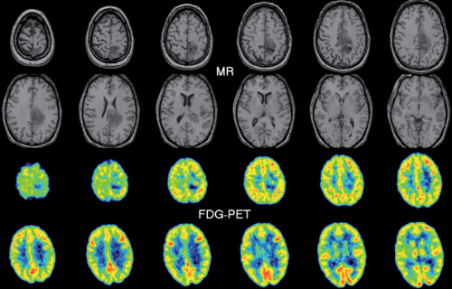 Figure 10.1 Traditional viewbox display of axial T1-weighted MR and FDG-PET images of the same person. Because of the different positioning and pixel sizes, the anatomic MR information cannot easily be correlated with the functional information from PET. |
Image Registration for Geometric Realignment
Image registration is always required for data sets acquired in different studies because a patient will always be differently positioned unless very cumbersome or unpleasant procedures are applied. Similar, although smaller, dislocations are likely to happen between consecutive acquisitions of one study because of involuntary patient motion. To prepare the ground for the ensuing discussion of different registration techniques, we start with a quick summary of the conceptual models and classification criteria involved.
Overview of Registration and Classification Criteria
A registration procedure that allows the matching of two data sets consists of the following components:
Role of the data sets. Although registration entails that both data sets end up aligned in a common coordinate space, it does not entail that both should actually be transformed. Transformations such as rotations involve interpolations that may degrade image quality, especially if the spatial resolution is nonisotropic (Fig. 10.2). Therefore, only the better resolved data set (the “model”) is transformed, whereas the other one (the “reference”) remains fixed.
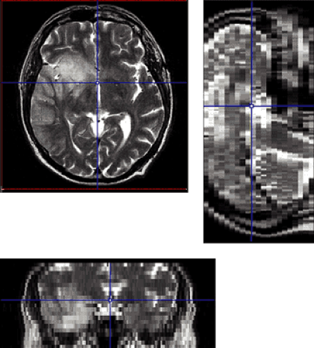
Figure 10.2 Nonisotropic resolution frequently met in anatomic image sets. The T2-weighted MR data set shown has a 512 × 512 × 23 matrix with 0.39 × 0.39 × 4 mm pixel size, which entails that the slice thickness is 10 times larger than the in-plane pixel resolution. Therefore, disturbing interpolation artifacts appear in the coronal and sagittal views, which would be propagated to any calculated oblique planes.
Information type. Registration procedures do not always operate on the full images but may rely on a set of derived
information features common to the objects represented in the two data sets. Examples include a set of anatomical landmarks and an organ surface detected in the images. These information features are collected in a preprocessing step. Often, user interaction is required, such as to point out corresponding anatomical landmarks or to guide the edge detection algorithm in segmentation procedures. However, depending on the image characteristics, the pixel values themselves can also be employed directly.
Allowed geometric transformation. There are two distinct classes of transformations, rigid transformations and elastic transformations. Rigid transformations assume that the object’s geometry is identical in both acquisitions and that the acquisition is distortion free. In this case, the transformation consists of a three-dimensional displacement (three parameters) and of a three-dimensional rotation (three more parameters). Differences in the size of the pixel edges are accounted for by three scaling factors. A rigid transformation is therefore determined by nine parameters. In most cases, however, the scaling factors are known from the image headers and need not be estimated. Elastic transformations allow a certain degree of image warping to cope with the fact that the boundaries of organs outside the brain change across acquisitions.
“Goodness-of-match” criterion. For an automatic registration method, the goodness of the alignment after a candidate transformation must be measurable. Only then can the transformation parameters be found that provide the best match between the reference features and the transformed model features.
Optimization. If the registration is not interactively done by the user him- or herself, an automatic optimization algorithm is required that brings the two image sets into agreement based on the extracted information and the allowed transformation. Usually it is not possible to find the optimal transformation by a single calculation. In these cases, iterative schemes are employed whereby the transformation parameters are systematically varied until no better match can be found. One problem with these algorithms is that they can find approximate solutions and miss the optimal match.
While a registration method can be characterized by the above five criteria, there are some additional relevant criteria with respect to a clinical application:
Prior requirements. The issue concerns the extent to which the registration method depends on special setups of the acquisitions. Examples include patient fixation techniques (Fig. 10.3) and the placement of external landmarks visible in the images. Further requirements might be related to image contrast and resolution or to the extent of organ coverage. If there are no such requirements, image data sets from previous studies or acquired at remote institutions can at any time be matched with newly generated images. It is clear that the ability to implement retrospective registration is very helpful in a clinical environment.
Objectivity and automation. Fully automatic registration techniques are highly desirable. In addition to being user-friendly, they offer operator independence and hence exact reproducibility. However, automatic methods are only a true advantage if the registration achieved is accurate enough. Usually, the input data for fully automatic methods cannot be arbitrarily acquired, but image acquisition must obey strict quality criteria. West et al. (1) point out that careful visual inspection of the results obtained from automatic registrations is crucial in a clinical setting.
Multi-modality registration. The image registration problem is easiest to solve for images acquired with one protocol on a similar scanner because they show the same information with the same resolution. If this condition is not fulfilled, registration becomes more difficult. Differences in resolution may not be a severe obstacle within certain limits. More difficult is the frequent case comparing functional and anatomical images where the images look very different.
In the rest of this section, several widely used registration techniques are discussed. We begin with rigid registrations and end with an elastic transformation that is frequently applied to transform functional patient data into
the normalized coordinate space of the stereotactic Talairach atlas (2). For a more in-depth review, the reader is referred to the reviews by Evans (3) and Maintz and Viergever (4), and for a performance evaluation, to the assessment of 16 retrospective registration methods by West et al. (1).
the normalized coordinate space of the stereotactic Talairach atlas (2). For a more in-depth review, the reader is referred to the reviews by Evans (3) and Maintz and Viergever (4), and for a performance evaluation, to the assessment of 16 retrospective registration methods by West et al. (1).
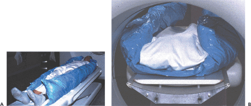 Figure 10.3 Fixation aid to restrict patient motion during examinations of the chest on two separate scanners. A: The patient is embedded into a mattress that, when evacuated, fits itself to the body contours. The shape is maintained throughout successive scans and efficiently limits patient motion, but this device is not liked by patients, as they tend to perspire profusely in it. B: To prevent errors arising from the table curvatures, a flat equalization board is used on both scanners. |
Interactive Registration
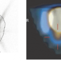
Interactive registration fully relies on the pattern-matching capabilities of a trained human professional, which is hard to surpass. An interactive registration tool can be used to specify trial transformation parameters, calculate the transformed model images, and present them jointly with the reference to allow the user to judge the goodness of the match. An example of a commercially available image fusion tool (http://www.pmod.com) is illustrated in Figure 10.4. The translation and rotation parameters of a rigid transformation can be specified by means of button presses or by directly dragging or rotating the model images, while the scaling factors are taken from the acquisition information in the image header. Three orthogonal slices of both data sets are shown in parallel, plus the fusion image, using the current transformation. Once the match is completed, corresponding slices will be shown. Assessment of the match is facilitated by various fusion display options, such as the inclusion of contours or a spyglass. The user incrementally modifies the transformation until the fusion confirms an adequate match.
Related posts:
 Brain Tumors: Astrocytoma, Oligodendroglioma, and Glioblastoma Images with PET and SPECT
 Sentinel Node Imaging in Head and Neck Tumors
 PET and PET-CT in Kidney Tumors and Bladder Cancer
 PET-CT and SPECT-CT of Bone Metastases
 SPECT and PET in Benign Thyroid and Parathyroid Disease
Stay updated, free articles. Join our Telegram channel

Full access? Get Clinical Tree


