Fig. 47.1
The image intensifier BV 20 was introduced by C.H.F. Müller (later to become Philips) in 1954. Optimized for surgery, the design of a C-arm with the X-ray tube on one side and the image intensifier on the other has endured for over 50 years (Reproduced with permission from Philips Healthcare)
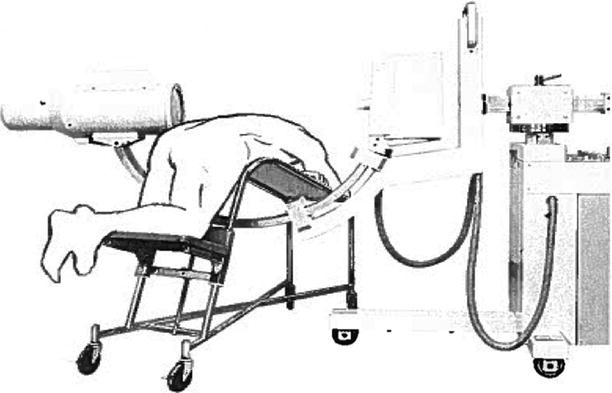
Fig. 47.2
The first application of the mobile C-arm for spine surgery in the United States is believed to date back to 1973, when Dr. John S. Collis at the Cleveland Clinic performed an intraoperative discogram with a C-arm provided by OEC. Dr. Collis invented a surgical table, later named after him, that allowed seamless use of the C-arm for discographies
Origins of Stereotactic Surgery and Its Application to the Spine
Recent developments that advance intraoperative image guidance are based on techniques originating in stereotactic brain surgery, the principles of which were introduced by Sir Victor Horsley and Henry Clarke in 1908 with a stereotactic apparatus to precisely target locations in the cerebella of apes [8]. They used the reproducible relationships between landmarks on the skull (external auditory canals, inferior orbital rims, midline), together with anatomical structures within the brain of the animal. The fixation points of the device on the crane served as a baseline for a three-dimensional (3D) Cartesian stereotactic coordinate system. Throughout the first half of the twentieth century, other investigators modified or reinvented refined stereotactic devices for application in humans [9].
For spine surgery, stereotactic principles were first used by Rand et al. [10] and Hitchcock et al. [11], who relied on head-mounted stereotactic frames for ablative procedures in the cervical spinal cord (Fig. 47.3). Heikkinen [12] used a modified Laitinen stereotactic device for localization of herniated lumbar discs.
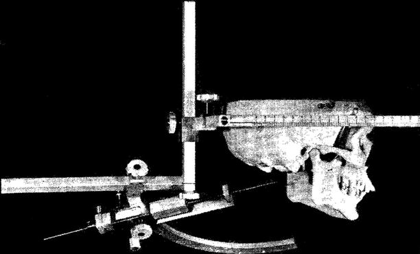
Fig. 47.3
Hitchcock et al. used a head-mounted stereotactic frame for ablative procedures in the cervical spinal cord (Reproduced with permission from Hitchcock et al. [11])
Evolution of Contemporary Image Guidance
The technique of localizing brain targets with stereotactic frames was based on using coordinates from a stereotactic brain atlas or by adapting the coordinates to the target–frame relationship after image acquisition that includes a head-mounted positional frame. For contemporary image guidance in spine surgery, images are acquired in a similar fashion, either by acquiring images after firm fixation of a dynamic reference array (DRA) to the spine or by an intraoperative registration step known as paired-point registration or a surface-matching technique if images are acquired without the stereotactic frame. Both methods are referred to as frameless image guidance, because the instruments used in navigation are not constrained to a frame.
In translating intracranial frameless navigation to the spine, Roberts et al. [13–15] evaluated the use of the stereotactic frameless microscope to assist in localizing pathological entities in the lumbar spine, such as herniated discs. Stereotactic microscopes use heads-up display technology that is superimposed on the surgeon’s field of view. Entering deeper into the spine from the skin surface, Brodwater et al. [16] noticed progressively decreasing accuracy, with the anticipated targets about 3 cm off the actual disc space. This inaccuracy was ascribed to the use of skin fiducial markers for registration, which would change position between the computed tomography’s (CT’s) scan acquisition, with patients in the supine position, and the intraoperative registration, which was performed with patients in the prone position. Target error was greatest in obese patients. Similar findings with the use of skin fiducial markers were reported by Roessler et al. [17].
This difficulty was overcome with the use of easily distinguishable anatomical landmarks on the spine as fiducial points for intraoperative registration. Nolte et al. [18, 19] presented a computer-assisted navigation system for preoperative planning and real-time intraoperative image localization of surgical instruments and demonstrated the feasibility of accurate pedicle screw placement in both a laboratory and a clinical setting. Registration could finally be omitted, using later technology such as iso-centric C-arm fluoroscopy (Siremobil Iso-C3D, Siemens Healthcare, Malvern, PA, USA) [20]. For the rest of this chapter, the terms image guidance and navigation will be used to refer to integrated systems rendering a real-time, 3D, or multiplanar image of the surgical site.
The Concept of the Multimodality Imaging Operating Room
In 1985, G. Jako introduced the modern concept of integrated multimodality imaging systems [21]. This system would guide surgeons using minimally invasive surgical instruments linked with updateable diagnostic data from CT, magnetic resonance (MR), and ultrasound, superimposed on the X-ray images in a procedure between the tissue and instrument localization and projected onto a video screen within a specialized computer-assisted operating room. F. Jolesz undertook the first clinical design and use of an open, “double-donut” MR imaging system built by General Electric (Fig. 47.4) [22]. The “double-donut” MR imaging system and the integrated multimodality imaging system utilized meaningful image-guided information, which later evolved into other image-guided innovations and procedures useful for enabling the performance of minimally invasive cranial and spine surgeries [23, 24].
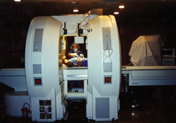
Fig. 47.4
Developed by General Electric starting in 1990, the open “double-donut” magnetic resonance imaging scanner was used for intraoperative imaging and image guidance in cranial and spine surgery. The open-configuration magnet design allowed surgeons to perform surgery within the imager and observe intraoperative images on the monitors within the patient access gap
Image Guidance and Minimally Invasive Spine Surgery
The evolution of image guidance in spine surgery developed in parallel with the vision and methods to perform spine surgeries through smaller incisions. The first such modern integrated device offering a less invasive approach for direct transperitoneal minilaparotomies and retroperitoneal exposures of the lumbar spine region was devised in 1990 by R. von Jako, who called it minimally invasive direct access surgical technology (MIDASTTM) [25]. The device was tested preclinically through an expandable 1- to 2.5-in. “operative window” for an anterior lumbar interbody fusion (mini-ALIF). Subsequently, the mini-approach was applied clinically for L4–S1 fusions (“the Howard–Jako technique”) in the US [26–28] and for L2–S1 fusions by H.M. Mayer in Germany [29]. The US patented device (the Jakoscope®, Atlantis Surgical, New Brunswick, NJ, USA; US patent nos. 5,503,617 and 5,813,978) was a self-retaining retractor–endoscope that featured interchangeable, radiolucent disposable blades capable of retracting and articulating independently by up to 50°, coupled with high-intensity xenon-light bifurcated fiber-optic cables (Fig. 47.5). The Jakoscope and the Howard–Jako and Mayer techniques consequently motivated and enabled the development of other similar minimal access devices that are today commonly applied to less invasive anterior to far-lateral spinal fusions. In these and other minimally invasive or percutaneous spine surgeries, image guidance can visualize unexposed anatomic landmarks for orientation and placement of navigated instruments and implants, thereby omitting the need for repeated C-arm use and radiation exposure (Fig. 47.6) [30–33].
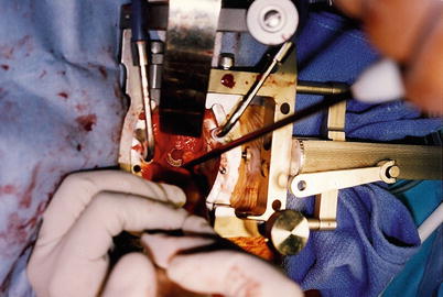
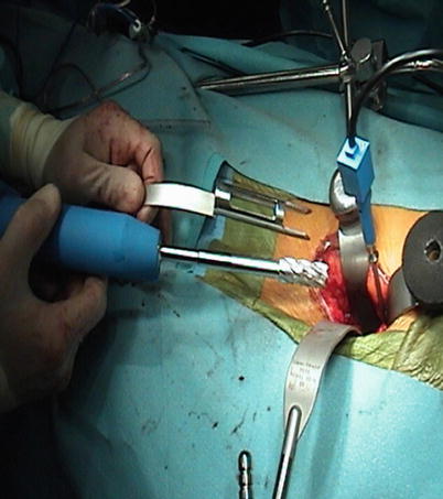
Fig. 47.5
The Jakoscope was the first lighted retractor–endoscope to enable spine fusions through small incisions. The use of this minimally invasive direct access surgical technique and technology (MIDAST) has allowed development of anterior to far-lateral interbody disc and fusion surgery in the lumbar–sacral spine
Fig. 47.6
Operative site of an anterior lumbar interbody fusion with the use of electromagnetic image guidance. The reference probe is attached to a modified Kirschner wire in the anterior vertebral body wall
Maxims of Image-Guided Spine Surgery
Any technological development used for image-guided spine surgery should aspire to assist the surgical team to perform procedures more safely and accurately, with more ease, and possibly at a faster pace than in traditional techniques. It should be quickly available and mobile or portable, and it should require minimal (or no) specialized personnel. Over the course of the investment, it should prove cost-efficient, as compared with conventional strategies of spine surgery. Procedural safety is particularly important for placement of pedicle screws, where most of the involved anatomy (pedicle, vertebral body) is hidden from direct surface view and must be inferred from exposed anatomical landmarks. Although real-time, 3D image guidance visualizes the passage of surgical tools through this otherwise obscured anatomy, any imprecision of the system, or its associated calibrated surgical tools, could cause unrecognized misplacement of hardware.
Principles of Image Guidance in Spine Surgery
Technical Equipment
The center of an image guidance system is a workstation that computes real-time images of the anatomy surrounding the tip of the navigated instrument. This instrument uses visual (reflectors, light-emitting diodes, miniature camera) [19, 34, 35], acoustic (ultrasound-emitting speakers) [15], or electromagnetic positional sensors [32], which are continuously tracked by a stereoscopic camera, microphone, or electromagnetic transmitter (Fig. 47.7). Each of these technologies has particular advantages and disadvantages, but all perform at an acceptable level of accuracy and reliability as navigation devices within the surgical environment.
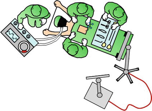
Fig. 47.7
The center of image guidance is the workstation with a screen that displays the navigated surgical tools in relation to patient anatomy. In this illustration, the workstation is connected to the electrooptical camera, which tracks navigated tools in relation to the firmly attached dynamic reference array. This setup is chosen for procedures from the cervicothoracic junction to the pelvis. The camera is set up over the patient’s head for procedures of the occipitocervical junction and upper cervical spine
Real-time images are reconstructed from a database of stored images by comparing the spatial relationship of the surgeon’s instruments with a rigidly attached reference array, which is placed on the patient’s spine. As opposed to frameless cranial stereotaxy, this reference array is only set up once the operative site is exposed and not beforehand. Furthermore, it may be repositioned during the procedure for intraoperative registration of multiple spinal levels, hence its name, dynamic reference array (DRA).
Optical Positional Tracking Technology
Light-emitting diodes (LEDs), also known as “active arrays,” or reflective spheres, known as “passive arrays,” are attached to the surgical instruments, as well as the DRA, and are monitored or tracked by the electrooptical camera array. The optical tracking digitizer measures the 3D locations of the arrays, and the information is transferred to the computer workstation, which computes a spatial frame-of-reference registration between the surgical and previously acquired image anatomy.
A recent novel approach to traditional optical tracking uses a miniature optical camera mounted on a surgical instrument (ActiViews, Inc., Wakefield, MA, USA), in combination with a sterile, self-adhesive patch containing fiducial markers placed on the patient’s skin over the entry site (Fig. 47.8) [36]. The benefit is that this elegant approach eliminates the cost and requirements associated with the floor- or ceiling-mounted electrooptical camera arrays and their associated line-of-sight issues [37–39].
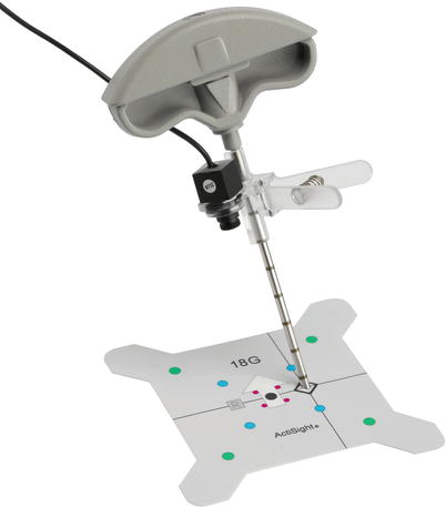
Fig. 47.8
A miniature video camera mounted on a medical instrument (needle trocar) for optical navigation (Reproduced with permission from ActiViews, Inc.)
Electromagnetic Tracking Technology
Electromagnetic (EM) tracking technology was invented and developed in the mid 1970s primarily for military use, as a helmet-mounted sight or display in fighter aircraft to augment optical technologies for guidance (Fig. 47.9). In the surgical environment, as in the plane cockpit, this technique requires precise magnetic mapping of the environment to account for ferrous and conductive materials, which can cause angular errors (distortions) in the measurement. Distortion mapping of a C-arm fluoroscope for common intraoperative uses serves this purpose. The main benefit of EM tracking for both the pilot and the surgeon is “non-shadowing,” which means that a clear line of sight between the sensor and source is not required. The main disadvantage of EM technology for use in surgical navigation is the field distortion in severely metallic environments. This can be addressed by tuning the EM system to its environment and creating instruments that are compatible with this type of tracking technology. Furthermore, the system notifies the surgeon immediately if a field distortion is detected. The disturbing metal can then be relocated or the tracking receiver repositioned. Using non-ferromagnetic instruments made out of 300-series stainless steel, plastic, or titanium minimizes the field distortion.
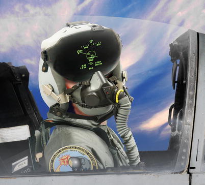
Fig. 47.9
Electromagnetic tracking technology was first developed for military use. Coils in the helmet are used to register position and motion in an electromagnetic field of the cockpit (Reproduced with permission from Vision Systems International)
Pre- and Intraoperative Procedures
In general, five steps have to be accomplished for image-guided spine surgery. (1) Calibration: All instruments that will be tracked during the surgery require calibration with the workstation. (2) Image acquisition: A radiographic image comprising the anatomy of interest is transferred to the workstation. This can be a preoperative CT scan or an intraoperative image (2D and 3D fluoroscopy). (3) Registration: The DRA is fixed to the spine, and predefined landmarks on the patient’s actual anatomy are touched with a tracked probe, allowing paired-point registration, as are a separate set of random points on the spine surface, allowing for surface-matching registration (Fig. 47.10). Some systems using intraoperative image acquisition, such as the TREONTM StealthStation® with O-arm® (Medtronic, Minneapolis, MN, USA), BrainLAB with ISO-C3D, ARCADIS® Orbic 3D (Siemens), or compatible intraoperative CT scanners, have an incorporated reference array that is tracked during image acquisition. Since the workstation then calculates the spatial relationships between the imaging frame of reference, the DRA on the spine, and the acquired image data set, the manual registration process is omitted [20, 35]. A third option for registration is the 2D–3D merge: The workstation merges the anteroposterior and lateral fluoroscopic images of the positioned patient with the preoperative CT. This is an automated registration process without the need for surface matching, and therefore, as with 3D fluoroscopy or intraoperative CT scanning, is applicable to percutaneous procedures [40]. Alternatively, axial images of the spine can be rendered by software using AP and lateral images from a conventional C-arm. FluoroCAT® (VTI, Lawrence, MA, USA, now GE OEC Medical Systems, Salt Lake City, UT, USA) was the first software that permitted this [41]. This software was followed by a more recent improvement, C-InSightTM (Mazor Surgical Technologies, Caesarea, Israel), which can also use a conventional C-arm to generate axial images of the spine. (4) Accuracy check: Anatomic landmarks are again touched with the tracked probe, and the correct image reconstruction is checked on the workstation. Any mismatch warrants a new registration procedure or a new intraoperative image acquisition, followed by an updated automated tracking/registration. (5) Navigation: The positions of all tracked instruments (probes, drill, tap, screwdriver) are observed in real time on the workstation as they are moved or manipulated.
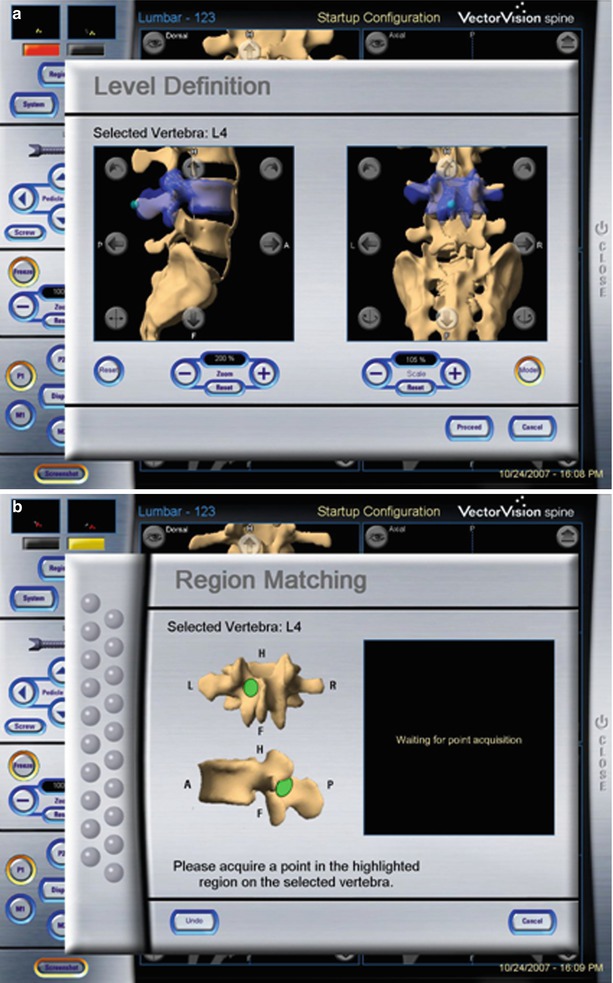
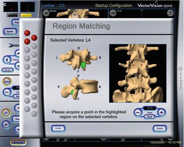
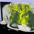
Fig. 47.10
Manual registration based on preoperative CT scan: First the level to be registered is selected by the surgeon (a). Then the workstation shows points on the lamina or spinous process that have to be touched with the tracked probe (b). Lastly, 12 further points are randomly touched on the exposed vertebra (c) (Reproduced with permission from BrainLab)
Indications for Image Guidance in the Spine
Image guidance is used to “look” beyond the exposed surface, at any location of the spine from the occipitocervical to the lumbo-pelvic junction and is usually used to guide placement of hardware. The instant visual feedback, showing where the tool or screw is located, either confirms that the desired trajectory is being followed or it allows for small adjustments to be made prior to inadvertent misplacements. In this respect, it is important to recognize that image guidance does not exempt the surgeon from a thorough understanding of vertebral anatomy and superficial landmarks [42–46]. Indeed, it is our strategy to localize the starting point for screw placements based on local anatomy, unless percutaneous approaches are chosen. Use of image guidance also warrants a reciprocal verification of the anatomy between what the surgeon sees and what the workstation shows.
Two features further underscore the potential role of image guidance for percutaneous spine surgeries. First, it continuously displays the unexposed anatomy in all planes, whereas standard techniques, using C-arm imaging, require repetitive imaging in multiple planes and only deliver static images unless the surgeon uses continuous fluoroscopy. Second, it does not expose the surgeon or patient to the increased radiation doses seen with conventional percutaneous spine surgery [7, 47].
Accuracy and Patient Safety
Image guidance may assist the surgeon to insert spinal instrumentation with an unprecedented precision and eliminate the misplacement of implants, thereby improving the safety of common procedures and making complex cases more accessible. Numerous studies have demonstrated the precise location of image-guided pedicle screws. A meta-analysis of a total of 37,337 pedicle screws found 91.3 % were accurately implanted in the combined in vivo and cadaveric populations [48]. The median accuracy for navigated screw placement in vivo was 95.2 %, as compared with 90.3 % for non-navigated pedicle screws. The authors of this meta-analysis found counterintuitive results for screws placed in the thoracic spine, in which the median accuracy was 94.3 % without navigation and 82.2 % with navigation. The authors suggested that this result may be confounded by the fact that highly experienced surgeons, familiar with traditional techniques but new to navigated instrumentation, placed the thoracic screws in these studies. In addition, earlier navigation systems were less accurate than contemporary devices are [35, 49]. A more recent single-center study on navigated pedicle screws in the upper thoracic spine found an accuracy of 93.3 % and noted that all pedicle violations were less than 2 mm [50]. Misplacement of upper thoracic pedicle screws using either anatomic landmarks alone or with intraoperative fluoroscopy was consistently higher, ranging from 6 to 41 % [51–54]. In the cervical spine, a cadaveric study on navigated percutaneous atlantoaxial and sub-axial lateral mass screws demonstrated an accuracy of 97.6 % [55].
For percutaneous screw placement in the lumbar spine, image guidance with the Iso-C3D and a spinal navigation system (VectorVision® compact, BrainLAB, Feldkirchen, Germany) was more precise than percutaneous screw insertion with fluoroscopy: Only 7.3 % of navigated screws were exposed, and none perforated the pedicle [56]. Of these, 1.3 % breached the medial pedicle wall and 6 % the lateral wall. In contrast, 12 % of fluoroscopic screws were exposed and 3.3 % perforated the pedicle. Of these, 5.3 % breached the medial pedicle wall, 8 % the lateral wall, and 2 % the caudal wall. In a clinical series of 278 pedicle screws placed with the O-arm and StealthStation TREON plus (Medtronic) from T11 to S1, only 3.2 % of screws were found at the medial border or breaching the medial pedicle wall [35]. Placement was always within 2 mm of the medial pedicle wall and did not require replacement. No other breach occurred. The difference between the actual and virtual angulation of the pedicle screws was 2.8° ± 1.9°. Nottmeier et al. [57] reviewed their experience with 1,084 navigated thoracolumbar screws in 220 patients, 46 % of whom had had prior thoracolumbar spine surgery. Most screws were inserted using the BrainLAB VectorVision, with the remainder using the Medtronic StealthStation TREON. A vertebral registration with paired-point/surface-matching algorithm was performed in 80 patients (314 screws), with a breach rate of 9.2 %. Automatic registration in 140 patients (637 screws) with the ARCADIS Orbic Iso-C3D, or the Medtronic O-arm, demonstrated a breach rate of 6.6 %. This difference was not statistically significant. Most breaches were pedicle wall breaches smaller than 2 mm or anterolateral “tip out” breaches in the vertebral body. The risk of nerve-root injury was 0.2 % per screw and 0.9 % per patient [57]. Navigated placement of pedicle screws can be particularly useful for revision of prior fusion surgeries, in which the anatomic landmarks may be lost or covered by the fusion mass. A 96 % accuracy was reported in the latter setting [58]. Ongoing studies evaluating the accuracy that can be achieved with EM navigation have shown equivalent or better accuracy of pedicle screw placement compared with traditional fluoroscopic guidance [31, 59, 60].
In summary, both traditional and navigated introduction techniques have a high safety profile for instrumentation of the thoracolumbar spine, but pedicle wall breaches appear to occur less frequently using navigated techniques. In addition, the use of 3D image guidance, instead of fluoroscopy, may persuade surgeons to choose larger screw diameters and a more triangulated approach trajectory, both of which are associated with higher pullout strength [57, 61–63].
Timing for Image-Guided Spine Surgery
The advent of image guidance for spine surgery has introduced to the operating theater new and complex technology that is associated with a learning curve for the surgical team. Skepticism about the adoption of image guidance into everyday spine practice may be reinforced by troubles that may arise during the first attempts to implement these complex systems. Although troubleshooting and subsequent use eventually yields a successful solution, the workflow of initial surgeries may be halted and valuable operating room time may be lost. Surgical staff who are well trained in the use of fluoroscopy may, therefore, abort the use of image guidance prematurely and complete a procedure conventionally without navigation. It is, thus, important to consider the time factor of established image-guided spine surgery. In systems that rely on the point and surface-matching method, every segment requires individual registration. This can be done within less than 2 min per level, at an accuracy of 1 mm [64]. Registration with 3D, fluoroscopy-based image guidance (Iso-C3D, ARCADIS Orbic 3D, O-arm) is automatic and encompasses multiple levels during one spin, but must be set up and performed during the surgery. A 3D C-arm spin involves movement of the C-arm through the full 190° gantry arc of a trajectory from the lateral projection through the anteroposterior to the contralateral projection for the purpose of generating a 3D reconstruction of the anatomy of interest. The O-arm provides a 360° rotation around the patient by the fixed gantry, which encloses the rotating internal flat-panel detector. This allows for very little structural flexion and much faster rotations without the concern for catching on drapes, equipment, or the patient. The required time from the attachment of the DRA to spinal navigation was reported to average 8 min and 34 s [64]. In another study, time for image acquisition (BrainLAB NaviVision®, ARCADIS Orbic 3D), registration of the instrumentation, and placement of screws for 2, 3, 6, and 8 screws averaged 20, 29, 38, and 51 min, respectively [65]. In our experience, it takes roughly 10 min to install the DRA, cover the surgical field, bring in and align the O-arm, perform a complete X-ray spin about the patient for image acquisition, check image quality, and retrieve the O-arm again. The learning curve for the serial steps is fast; however, the technical staff must be trained in operating the O-arm. Tracked instruments are registered by the scrub technicians automatically as they lay out the instruments before the surgery. Because registration can be performed while the patient is placed under anesthesia or during surgical exposure, it does not add to the duration of surgery. In fact, intraoperative navigation for spine surgery has been demonstrated to ultimately accelerate surgery [66].
Radiation Exposure to Surgeon and Patient
Image guidance technology is invariably linked to ionizing radiation and its health concerns regarding carcinogenesis. For instance, a significantly increased rate of cancer has been documented in the cohort of atomic bomb survivors who were exposed to low-dose radiation above 50 mSv [67]. The public is exposed to 3.6 mSv per year (3-mSv background radiation, 0.6 mSv from medical exposure) [68]. The estimated effective doses for cervical, thoracic, and lumbar spine CT are 3.45, 10, and 5.6 mSv, respectively [69]. Ideally, image guidance in spine surgery should achieve a reduction of the cumulated dose in a given patient and also eliminate exposure to the surgical staff. Since spine patients are likely to need multiple CT studies for diagnosis, preoperative planning, postoperative control, and follow-up, the dose and stochastic effects may reach concerning levels. Whereas the risk to develop cancer might still be very low for the individual scanned patient, it was estimated that 2 % of all cancers in the United States originate from CT studies [70]. With standard fluoroscopy-assisted pedicle screws placement, the effective whole-body dose absorbed by the patient from radiation beam entrance to the lumbar spine during a fluoroscopic screening time of 1.4 min (4 pedicle screws) was estimated at 2.3 mSv, for the source-superior (posteroanterior), and 6.9 mSv for the source-inferior (anteroposterior) positions [71].
Related posts:
 Visualization and Display for Image-Guided Therapy
 Multimodality Navigation in Neurosurgery
 Image-Guided Robotics in Minimally Invasive Therapies
 Innovations in Ultrasound Instrumentation for Image Guidance
 Image-Guided Prostate Brachytherapy
 CT-Guided Interventions: Current Practice and Future Directions
Stay updated, free articles. Join our Telegram channel

Full access? Get Clinical Tree


