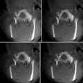
Fig. 11.1
(a) A 16 × 16 2-D CMUT array flip-chip bonded on the first-generation custom front-end integrated circuit. (b) The synthetic aperture 3-D image of a wire phantom. (c) A 16 × 16 2-D CMUT array flip-chip bonded on the second-generation custom front-end integrated circuit with transmits beamformer. (d) The phased array 3-D image of a wire phantom
Photoacoustic Imaging
Photoacoustic imaging is a promising medical imaging modality that provides functional information by combining the contrast information of optical imaging with the spatial resolution of acoustic imaging. In photoacoustic imaging, the target tissue is illuminated with short laser pulses that cause brief heating of absorbing structures such as blood vessels. The induced temperature increase in the range of mK generates acoustic pressure waves because of the thermoelastic effect. These pressure waves propagate to the surface of the tissue where they can be detected with ultrasound transducers. Photoacoustic imaging has been typically performed using a single mechanically scanned focused piezoelectric transducer for detection of the laser-generated ultrasound. Using a 2-D CMUT array instead of a mechanically scanned element has various advantages. 3-D images can be acquired in one shot using large 2-D arrays, which can be reliably fabricated using CMUT technology. To demonstrate the potential of CMUTs for photoacoustic imaging, we used the 16 × 16 element 2-D CMUT array described in section “Integrated Miniature 2-D Arrays for Real-Time 3-D Intracavital Imaging” to image indocyanine green (ICG) and blood-filled polyethylene tubes embedded in chicken breast tissue (Fig. 11.2a) [24]. We used double-sided laser illumination at a wavelength of 775 nm to gather the photoacoustic data since the peak ICG absorption is at this wavelength for the concentrations used. The 16 × 16 CMUT array and tank were mounted on a precision x-y translational stage to enable planar scanning and emulation of a 64 × 64 element CMUT array. A photoacoustic image reconstructed from this data is equivalent to that of an image reconstructed using a 64 × 64 element CMUT array (Fig. 11.2b). Recently, we demonstrated the photoacoustic imaging depth can be extended up to 5 cm (deeper than other reported results using conventional ultrasound detector technologies) without exceeding the permitted laser exposure limit (20 mJ/cm2 per pulse) mainly enabled by the superior noise performance of 2-D arrays with integrated front-end circuits [25].
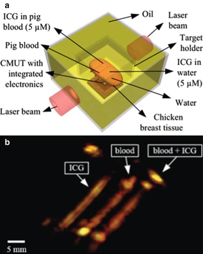
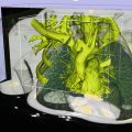
Fig. 11.2
(a) The photoacoustic imaging phantom that consists of polyethylene tubes embedded in chicken breast tissue. (b) The 3-D photoacoustic image of the phantom
Intracardiac Echocardiography Catheters
Atrial fibrillation (AF) is the most common type of cardiac arrhythmia that now affects more than 2.2 million adults in the United States alone [26]. AF is caused by erratic electrical signals originated from the atria that interfere with heart’s sinus rhythm. This condition causes the atria and the ventricles to contract erratically and may lead to blood clots and stroke.
Electrophysiological (EP) studies provide valuable information about the heart’s conduction system. During such studies, an electrophysiologist may provoke arrhythmia events to map the electrical behavior of the heart and locate the specific areas of the heart that give rise to the abnormal electrical impulses causing the arrhythmia. Consequently, a proper treatment, which may include ablation therapy, can be applied.
The EP interventions are most commonly performed using multiple catheters. The most common method of catheter positioning during these procedures is fluoroscopy. However, the ionizing radiation involved with fluoroscopy is undesirable for both the patient and the practitioner [27]. Additionally, fluoroscopy provides poor soft tissue resolution and even with the use of contrast agents, it does not provide adequate anatomical information for accurate catheter positioning [28]. Therefore, the use of intracardiac echocardiography (ICE) for the guidance of EP interventional procedures is attracting more attention. Besides reducing the exposure to harmful ionizing radiation, ICE improves the visualization and procedural guidance compared to fluoroscopy alone [29].
We have designed and developed two types of multifunctional, fully integrated CMUT ICE catheters, namely, MicroLinear (ML) and Ring catheters, for real-time, forward-looking imaging.
The ML catheter uses a 1-D, 24-element CMUT phased array at the catheter tip that enables real-time, forward-looking 2-D imaging (Fig. 11.3). The Ring catheter uses a ring-shaped, 2-D, 64-element CMUT array that enables real-time, forward-looking volumetric imaging (Fig. 11.4). Both arrays were designed for a center frequency of 10 MHz. Through-wafer electrical vias were incorporated in the CMUT arrays to provide electrical access to individual array elements through the backside of the devices for tight integration.
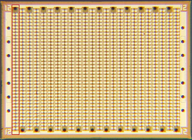
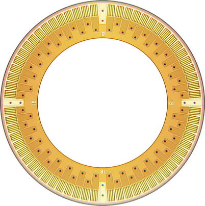
Fig. 11.3
Photograph of the front side of an ML array composed of circular CMUT cells. The total footprint of the array measures 1.73 × 1.27 mm. The red box depicts a single array element
Fig. 11.4
Photograph of the front side of a Ring array composed of rectangular CMUT cells. The outer and inner diameters of the array measure 2.54 and 1.63 mm, respectively
We also designed custom front-end electronics for close integration with the CMUT arrays to improve the signal integrity and, thus, the final image quality. We used a flexible PCB as an intermediate substrate to integrate the arrays with the custom electronics and also provide the means for coaxial cable connection to each electronics channel. The CMUT arrays and the electronics dice were integrated with their custom flexible PCBs using the flip-chip bonding method that incorporates solder bumps for interconnections. After the integration, the flexible PCBs were folded under the CMUT arrays for integration with catheter shafts (Fig. 11.5).
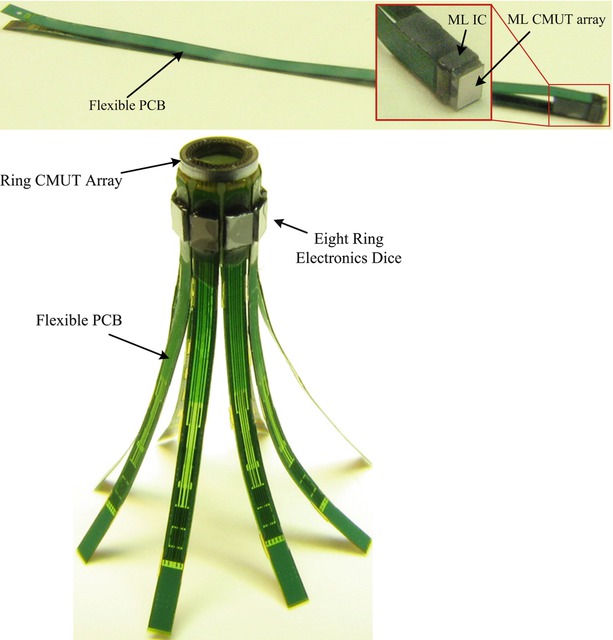
Fig. 11.5
Photograph of the ML and Ring assemblies after integration with flexible PCB. The top figure shows an ML assembly, and the bottom figure shows a Ring assembly
A photograph of the distal end of a finalized ML catheter is shown in Fig. 11.6. In addition to the real-time, forward-looking 2-D imaging capability, this catheter is equipped with a metal tip enclosure for RFA and an EP sensor band. As well as providing EP electrical mapping, EP sensor bands may be utilized for 3-D electroanatomical mapping of the heart for enhanced procedural guidance.
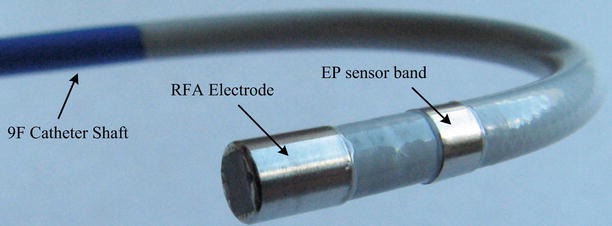
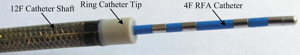
Fig. 11.6
Photograph of the distal end of a finalized 9F ML CMUT ICE catheter
A photograph of the distal end of a finalized Ring catheter is shown in Fig. 11.7. Besides the real-time, forward-looking volumetric imaging capability, the Ring ICE catheter enables additional functionalities through its inner lumen. This inner lumen may be utilized for convenient delivery of other devices for a variety of applications (e.g., RFA, laser ablation, EP diagnosis, biopsy, photoacoustic imaging), under the guidance of or in combination with ultrasound imaging. Figure 11.7 also shows a 4F RFA catheter introduced through the inner lumen of the Ring catheter as an illustration of the multifunctionality of this catheter.