Fig. 31.1
MRI-compatible robot developed for 0.5-T open-configuration MRI scanner (Figure courtesy of Dr. Kiyoyuki Chinzei, National Institute of Advanced Industrial Science and Technology, Japan)
Surgical Computer-Aided Design and Computer-Aided Manufacturing
According to Taylor and Stoianovici’s definition [13], MRI-compatible robots reported so far are generally classified as surgical computer-aided design and computer-aided manufacturing (CAD/CAM) robots as opposed to surgical assistant systems to enhance surgical skills such as suturing. Unlike surgical assistant systems like the da Vinci master-slave robot (Intuitive Surgical, Sunnyvale, CA), the primary advantage of the surgical CAD/CAM robots is the high-precision guidance of surgical tools, such as biopsy needles or ablation applicators using intraoperative imaging for planning and guidance. Preprocedural MRI images can provide the most recent examination of a patient’s anatomy to identify a target and critical surrounding tissue and plan a trajectory to the target that avoids damage to critical anatomies. MRI-compatible robots are particularly useful for guiding the tools to the target following the planned trajectory and executing the treatment plan. All of the early developments of MRI-compatible robots, including ones by Masamune et al., Chinizei et al., and Kaiser et al., follow a similar principle.
Clinical Applications
A review article by Elhawary et al. outlines the engineering components of MRI-compatible robotics [14], focusing less on the clinical aspect of the MRI-compatible robots. This chapter will first focus on the clinical deployment of the MRI-compatible robots, which mostly happened after Elhawary et al.’s article was published. We will then discuss the recent advancements of MRI-compatible robotics as well as emerging core technologies useful for the robots.
Breast Biopsy
One of the first MRI-compatible robots deployed in clinical applications was ROBITOM, developed by the Institute for Medical Engineering and Biophysics (IMB, Forschungszentrum, Karlsruhe, Germany). The robot was another type of motorized stereotactic frame for a biopsy used to approach a lesion found in the breast in an image-controlled manner under a high magnetic field (1.5 T) [10]. The robot was designed to be placed in the direct vicinity of the isocenter of a magnet. The robot consists of a trocar, coaxial sleeve, and biopsy needle. An MRI-compatible plastic rack contains two piezo motors each motorized by an ultrasonic motor that drive an extension arm along the x– and y-axes. The distal end of the extension arm facing the patient holds an adapter. The adapter is used to perform local anesthesia, skin incisions, as well as to insert a trocar and a 14 g-LCBB needle in a coaxial technique. A clinical validation study of ROBITOM has since been conducted [15, 16]. In [15], the authors report the use of ROBITOM to perform core-needle biopsies from lesions with an average size of 18.6 ± 12 mm in 14 subjects.
Transrectal Prostate Biopsy
Another group from the Netherlands also active in MRI-compatible robotics has developed a motorized version of a transrectal prostate biopsy device now commercially available [17]. The study has been published as both an engineering paper [18] and a clinical paper [19]. These papers mentioned, but did not discuss in detail, the importance of performing failure modes and effects analysis (FMEA) to ensure the safety and reliability of the robot. While no details were given concerning FMEA of the particular robot proposed, the introduction of the concept itself was useful for researchers in the MRI-compatible robotics community. The robot has been applied to ten biopsy cases in 3-T MRI-guided biopsies and successfully collected 76 % of the image-defined lesions [19]. The rest of the lesion was reached by manual needle placements.
A notable mention in MRI-guided robotics research for prostate intervention is the UMCU (University Medical Center Utrecht, Netherlands) robot [20] which has been used for gold seed placement through a transperineal approach in a 1.5 T scanner. This robot is equipped with a pneumatically driven tapping device to automatically insert a needle stepwise into the prostate using a controller unit outside the scanning room. The needle placement stage is moved manually, but the final needle insertions are performed using a tapping mechanism. This approach is philosophically distinctively different from the other robots, where the robots were used for precision placement of the apparatus, whereas this robot uses a motorized mechanism to facilitate the needle insertion itself. For planning, four gold markers are placed transperineally inside the prostate using two parallel needle trajectories set manually using preprocedural MRI images.
Liver Tumor Ablation
Our research group has developed and clinically deployed a needle-guiding manipulator to assist in precise and accurate needle placement for MRI-guided microwave ablation of liver cancer. The manipulator was specifically developed for an open-configuration MRI scanner, which allows the coexistence of the manipulator and a physician in the open work space between the donut-shaped magnets. The role of the manipulator is to restrict the needle trajectory to a pivoting motion, yet retain the physician’s ability to select the optimal needle trajectory interactively. Specifically, the objective and technical contribution of our novel approach was to design, build, and test the MRI-compatible surgical manipulator with two unique design features: a Virtual remote-center-of-motion (RCM) mechanism and synergistic human-machine interface control. The Virtual RCM control keeps the needle tip aimed at the predefined tumor site, while the synergistic human-machine interface enables a physician to select the needle insertion path interactively. Unlike the other clinically deployed robots, which perform the automated placement of the needle or apparatus, our manipulator was designed to accomplish the coordinated task execution by a person and the manipulator. After technical validation of the manipulator [21], it was applied in 15 cases to treat liver tumors in various locations. Thoracoscopic assistance was combined with the manipulator in six cases (Fig. 31.2a, b).
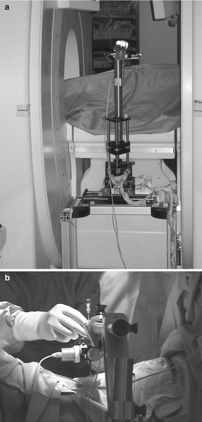
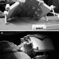
Fig. 31.2
Needle guidance robot with virtual remote-center-of-motion. (a) Placement of the robot in the gap of the 0.5T open-configuration scanner, and (b) hands-on manipulation of the robot end-effector for precision needle placement
General Percutaneous Therapy
Perhaps the most advanced MRI-compatible robot that has been developed, clinically validated, and commercialized is the INNOMOTION robot (Synthes Innomedic GmbH, Herxheim, Germany) developed by Melzer et al. [22] for percutaneous placement of needles in an MRI scanner. Its C-shaped outer arm fits tightly into the 60 cm bore of a standard MR scanner to enable biopsy needle guidance. In Leipzig, Germany, Moche et al. performed two biopsies in bone (femur and sacral), three other biopsies in different regions not subject to organ motion (lesser pelvis, iliac lymph node, lumbar spine abscess), and one in a region subject to respiratory motion (liver) [23]. The authors stated that a stereotactic device such as INNOMOTION assists in the biopsies of lesions that are hard to reach, difficult to align through the mental mapping of the trajectory, or found in regions with few anatomical reference points. The same principle applies to most CAD/CAM robots in MRI-guided therapies.
Engineering Approaches
Preclinical Robots
MRI-compatible robotics has also focused on applications for prostate interventions [24]. Investigators at Johns Hopkins University have been active in developing MRI-compatible robots for prostate interventions and have attained significant achievements. Stoianovici’s team at the Department of Urology has been active in developing original pneumatics motors tailored specifically for MRI-compatible use [25]. The first pneumatic step motor, PneuStep, sequentially pressures the ports of the motor using pulsed pressure waves. The motor assembly includes a motor, gearhead, and incremental position encoder in a compact, central bore construction. Stoianovici’s team applied the actuator to urological applications and reported numerous successful preclinical validation and clinical applications [25–31].
Fitchtinger and Whitcomb’s group also developed an MRI-compatible robot for transrectal use, building upon a manual version of their robot [32–36]. The robot developed by this group is a motorized and passive transrectal needle placement device for prostate interventions. The method reported includes the registration of the robot to the MRI’s coordinate system using fiducial markers. The same group has also worked with us to develop an MRI-compatible robot for transperineum use using pneumatic motors and linkage arms [37–44]. A group from the UK [45, 46] also reported a series of robots in MRI-guided prostate interventions, but these have not reached clinical implementation (Fig. 31.3).
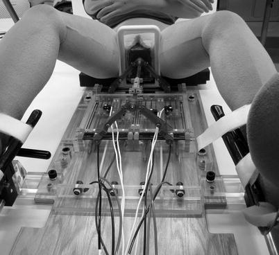
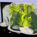
Fig. 31.3
A small profile MRI-compatible pneumatic needle placement robot to angulate a needle insertion path into a prostate
A skin-mounted needle puncture robot was developed and reported by a team of scientists from Grenoble, France. The purpose of the robot was to perform percutaneous needle insertion in CT and MRI scanners under imaging guidance. The device consists of two parts: the first is the needle insertion device controlled by three-degree-of-freedom motion and the second provides motorized translational movement over the skin to localize the needle insertion device by two-degree-of-freedom motion. The benefit of using this mechanism is that one can place the whole device on a patient’s skin and avoid trauma caused by sudden uncontrolled movement of the patient. The motion is controlled by pneumatic motors to minimize image degradation.
MRI Compatibility
The article by Chinzei et al. [47] and Elhawary et al. [48] is a good start to understand the challenges and potential solutions to the problem of MRI compatibility in medical robotics. Since traditional electromagnetic components interact with and become dysfunctional due to the high magnetic field of an MRI scanner, researchers are working on special MRI-compatible actuation and sensor technologies including pneumatic actuators, hydraulic actuators, ultrasonic motors for actuation, and optical sensors for position, force, and torque detection. The requirement of MRI compatibility initially created major difficulties for early MRI robotics investigators. However, experimental and theoretical studies originally released online by GE Medical Systems (GE Healthcare, Milwaukee, WI) but also re-reported by Chinzei et al. in [11] gradually established the design criteria to build MRI-compatible machines. Chinzei et al’s paper outlines various important notions in MRI-compatible robotics. It established, for example, that the MRI environment be within the five gauss line of the MRI scanner: any engineering devices within the five gauss line should be MRI compatible. MRI compatibility itself is precisely defined as a combination of (1) MRI safe, (2) no interference to image qualities, and (3) proper operation of the compatible device itself. The engineering details of these three aspects of MRI compatibility are outlined in the paper, including examples of proper material selection or electric engineering solutions.
A general review of MRI compatibility and safety test protocols on MRI-compatible robots based on the American Society for Testing and Materials’ (ASTM) international guidelines is summarized in Schaefers [49]: the test protocols to measure magnetically induced forces (ASTM F2052), magnetically induced torque (ASTM2213), heating and induced voltages due to the electromagnetic environment (ASTM F2182), and image quality (IEC 62464–1) [50]. The article also touches upon proper labeling to indicate the completion of the testing. No expert review on safety and compatibility tests has been published since Schaefers’ article, making it the most contemporary guideline in compatibility validation in MRI-compatible robotics.
Materials
The quantitative measure to predict image distortion and magnetically induced forces and heat is magnetic susceptibility. It has been suggested that the materials near or close to the imaging field should be diamagnetic or slightly paramagnetic [48]. The materials for parts very near or in the imaging field should have a dielectric coefficient close to that of air. Such materials include but are not limited to copper, alumina ceramics, and plastics. Aluminum, titanium, and magnesium may be used near the imaging field if the volume of the material is limited. One should be careful in balancing the rigidity of the mechanical structure and magnetic susceptibility of the material used for the structure, as materials low in susceptibility tend to be less rigid and may compromise the accuracy of the mechanical motion. For this reason, researchers also try to use a specific 300 series stainless steel [47] for linear guides and ceramic bearings [21] for contact parts (Fig. 31.4).
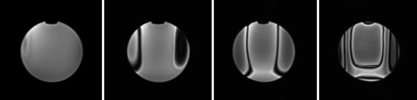
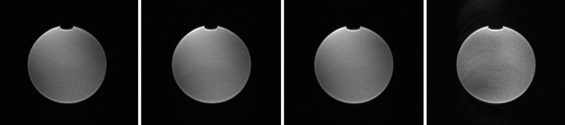
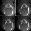
Fig. 31.4
A series of axial gradient-echo images (top) acquired from a 3-T MRI scanner showing distortion effect created by Brass-alloy parts of a MRI-compatible robotic device. In this example, the metallic structure was located 114 mm away from the imaging center. The images (from left to right) were acquired at 54, 66, 78, and 90 mm from the imaging center. Visible distortion reached approximately 60 mm from the parts
Actuators
In principle, researchers have found ultrasonic motors to be the preferred choice for actuators. There are commercial ultrasonic motors using no ferrous materials in their casings available in the market. The companies that produce such MRI-compatible ultrasonic motors are Piezo Motor AB, (Uppsala, Sweden), Nanomotion (Yokneam, Israel), and Shinsei corporation (Tokyo, Japan). Piezo Motor and Nanomotion produce linear motors that may be useful in particular clinical applications. In designing a mechanism using these ultrasonic motors, the locations of the motors have to be carefully considered to avoid image distortion due to the motors’ electrical circuitry. The strategy we took to avoid distortion was to place the actuators away from the scanner up to two meters above [51] or a meter below the imaging field [21]. It is this author’s personal impression that modern MRI scanners have better distortion correction methods implemented in the imaging sequence, allowing us to place the motors closer to the imaging field than before. In a recent study, we placed Shinsei’s ultrasonic motors approximately 30 cm from the isocenter of the imaging field in a 3-T MRI scanner and found negligible image distortion [52].
The other major solution in selecting MRI-compatible actuators is to develop custom pneumatic actuation methods. Fisher et al. and our team at Brigham and Women’s Hospital developed a linear actuation method using piezoelectrically actuated proportional pressure valves combined with Airpel 9.3-mm bore cylinders [39]. For a safety measure, custom MRI-compatible pneumatic brakes were developed and installed in the study. Another custom development in pneumatics motors includes the pneumatic stepper motor by Stoianovici et al. [25] (Fig. 31.5).