Chapter 14 Image quality


 Understanding the cause of faults will ensure rectification of the cause and improved image quality.
INTRODUCTION
One of the fundamental roles of practitioners in radiography is to produce optimum radiographs for reporting. Image quality is difficult to define because it is subjective in its nature, but an optimum quality image enables the observer to extract information from the image and make an accurate diagnosis. Poor quality images have a poor signal-to-noise ratio and detract from the process of extracting information. However, there are characteristics of a radiograph, which may be evaluated, and enable the practitioner to distinguish the diagnostic quality of the image. These factors include:
MAGNIFICATION
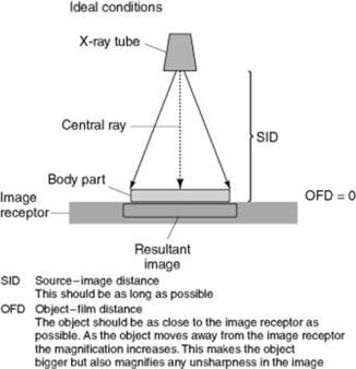
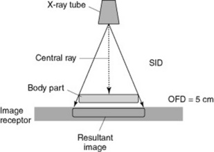
When producing a radiographic image all objects in the image are larger than the object being X-rayed. This magnification is due to the geometry of imaging. The ideal situation is to have the object being X-rayed as close as possible to the image receptor, parallel to the X-ray tube and the image receptor, with the radiation beam at right angles to the object. This minimises the magnification of the image but also, more importantly, the magnification of the unsharpness in the image (Figs 14.1 and 14.2).
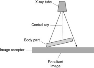
If the object being imaged is not parallel to the image receptor it will be magnified; however, each end will be magnified differently and this will produce distortion. This may be elongation or foreshortening of the image (Fig. 14.3).
The focus to image receptor (SID; see p. 91) should be as long as possible and the distance between the patient and the image receptor (object–film distance, OFD) as short as possible. For practical reasons the SID is usually 110 cm for techniques on the X-ray table and 180 cm for chest and cervical spine erect film work. The OFD should be as close as possible and ideally the object is in contact with the image receptor. Using a Bucky assembly also causes magnification of the image but the grid is necessary to reduce scatter and improve the contrast of the image. Practically, the mechanism which moves the grid and houses the Bucky is kept as small as possible.
SHARPNESS
RESOLUTION OF THE IMAGING SYSTEM
This is covered in more detail in other chapters of the book (see pp. 141, 154). However, it should be noted that the fastest film-screen combination or exposure index compatible with diagnostic quality should be used. When determining the quality required in an image the practitioner must be aware of what structures need to be defined. An image to determine the position of bones in a plaster cast following an orthopaedic reduction needs less resolution than the original image to diagnose the fracture. Ideally the smaller of the foci of the X-ray tube should be used (fine focus) but if this does not enable a short exposure time to be used on a patient likely to move then the practitioner may need to use a broad focus. This is another example of where the practitioner needs to make a decision that is a compromise between the ideal conditions and getting a diagnostic image.
GEOMETRY OF IMAGING
The positioning of the patient (geometry) to produce an image has a direct relationship to the quality of that image. The section on magnification (p. 162) outlined the ideal conditions needed to produce radiographic images and dealt with the requirements to reduce magnification (p. 163). It also emphasised that any increase in the size of the object also increases the unsharpness of the image and this will be explored in this section.
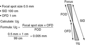
Figure 14.4 is a diagrammatic representation of image production and shows that a penumbra (unsharpness) is formed with any image that is produced from a finite source (focal spot). The diagram uses a large distance between the object and image receptor to illustrate the principle of the penumbra. In practice the amount of geometric unsharpness (Ug) in an image is small and may be much less than 1 mm.
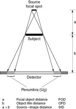
Measurement of the penumbra (Ug) is a straightforward calculation using similar triangles. Figure 14.5 demonstrates the diagrammatic representation of similar triangles and the calculation to determine unsharpness in an image ofa finger due to geometric unsharpness. The values used are typical in radiography and the unsharpness is only 0.005 mm.