Chapter 6
Image Receptors and Image Acquisition
After completing this chapter, the reader will be able to perform the following:
1. Define all the key terms in this chapter.
2. State all the important relationships in this chapter.
3. Differentiate among the types of image receptors (IRs) used in radiography.
4. Compare and contrast the construction of digital and film-screen IRs in order to acquire the latent image.
5. Differentiate between computed radiography (CR) and direct digital radiography (DR) IRs.
6. Explain the relationship between sampling frequency and spatial resolution.
7. Describe how the size of a CR imaging plate can affect spatial resolution.
8. Recognize the differences between indirect and direct conversion digital IRs.
9. Compare film-screen and digital IRs in terms of their dynamic range and explain the importance of dynamic range in exposure technique selection and image quality.
10. Define signal-to-noise ratio (SNR), and explain its importance to digital image quality.
11. Define sensitometry, and discuss film speed, contrast, latitude, and spectral sensitivity.
12. Explain the use of intensifying screens in film-screen imaging.
13. Recognize the effect intensifying screens have on image quality and patient radiation exposure.
During radiographic imaging, the radiation exiting the patient is composed of a range of intensities that reflect the absorption characteristics of the anatomic tissues. The image receptor (IR) receives the exit radiation and creates the latent or invisible image. The latent image is acquired differently depending on the type of IR. This chapter describes the common types of IRs used in radiography and how the latent image is formed. Latent image processing and display of the visible image are discussed in Chapter 7.
Digital Image Receptors
Computed Radiography
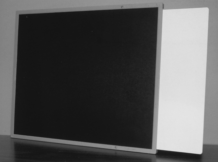
CR IRs can be portable or fixed in a table or upright x-ray unit. The CR IR includes a cassette that houses the imaging plate (IP) (Figure 6-1). The radiation exiting the patient interacts with the IP, where the photon intensities are absorbed by the phosphor. Although some of the absorbed energy is released as visible light (luminescence), a sufficient amount of energy is stored in the phosphor to produce a latent image. Luminescence is the emission of light when stimulated by radiation.
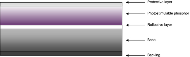
The IP primarily consists of a support layer, phosphor layer, and protective layer (Figure 6-2). The phosphor layer is composed of barium fluorohalide crystals doped with europium, referred to as the photostimulable phosphor (PSP). This type of phosphor emits visible light when stimulated by a high-intensity laser beam, a phenomenon termed photostimulable luminescence.
CR imaging requires a two-step process for image acquisition: image capture in the IP and image readout. The latent image is formed in the PSP when the exit x-ray intensities are absorbed by the phosphor and the europium atoms become ionized by the photoelectric effect. The absorbed energy excites the electrons, and they are elevated to a higher energy state where they become stored or trapped (Figure 6-3). The number and distribution of these trapped electrons are proportional to the tissue’s differential x-ray absorption and form the latent image. These electrons remain in this higher energy state until released during the laser beam scanning of the readout stage. The acquired image data (released energy) are extracted from the digital receptor, converted to digital data, and computer processed for image display. Exposed IPs should be processed within a relatively short amount of time (within 1 hour) because the latent image dissipates over time.

 Important Relationship
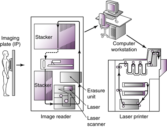
The exposed IP is placed in or sent to a reader unit that converts the analog data into digital data for computer processing (Figure 6-4). Reader units are available in single-plate or multiplate configurations. The major components of a typical reader unit are a drive mechanism to move the IP through the scanning process; an optical system, which includes the laser, beam-shaping optics, collecting optics, and optical filters; a photodetector, such as a photomultiplier tube (PMT); and the analog-to-digital converter (ADC). Manufacturers differ in the CR reader mechanics. Some devices move the IP, and some move the optical components. There are three important stages in digitizing the latent image: scanning, sampling, and quantization.
The purpose of scanning is to convert the latent image into an electrical signal (voltage) that can be subsequently digitized and displayed as a manifest digital image. Once in the reader unit, the IP is removed from the cassette and scanned with a helium-neon laser beam or a solid-state laser diode to release the stored energy as visible light (Figure 6-5). Absorption of the laser beam energy releases the trapped electrons, and they return to a lower energy state. During this process, the excess energy is emitted as visible light (photostimulable luminescence). The scanning of the plate results in a continuous pattern of light intensities being sent to the PMT, whose output is directed to the ADC for sampling and quantization.
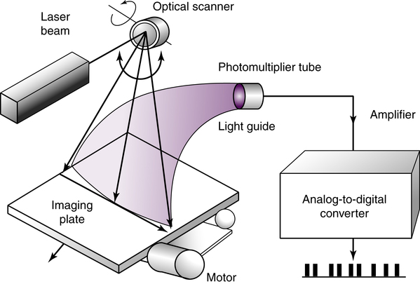
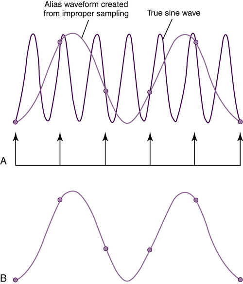
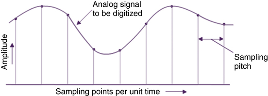
A PMT collects, amplifies, and converts the visible light to an electrical signal proportional to the range of energies stored in the IP. The signal output from the PMT is digitized by an ADC in order to produce the digital image. To digitize the analog signal from the PMT, it must first be sampled. An important performance characteristic of an ADC is the sampling frequency, which determines how often the analog signal is reproduced in its discrete digitized form. Increasing the sampling frequency of the analog signal increases the pixel density of the digital data and improves the spatial resolution of the digital image (Figure 6-6). The closer the samples are to each other (increased sampling frequency), the smaller the sampling pitch, or distance between the sampling points (Figure 6-7). Increased sampling frequency decreases the sampling pitch and results in smaller-sized pixels. The distance between the midpoint of one pixel to the midpoint of an adjacent pixel describes the pixel pitch. Spatial resolution is improved with an increased number of smaller pixels resulting in a more faithful digital representation of the acquired analog image.
 Important Relationship
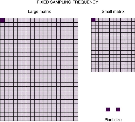
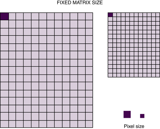
Manufacturers of CR equipment vary in the method of sampling IPs of different sizes. Some manufacturers fix the sampling frequency to maintain a fixed spatial resolution, whereas others vary the sampling frequency to maintain a fixed matrix size. If the spatial resolution is fixed, the image matrix size is simply proportional to the IP size. A larger IP has a larger matrix to maintain spatial resolution (Figure 6-8). If the matrix size is fixed, changing the size of the IP would affect the spatial resolution of the digital image. For example, with a fixed matrix size system, changing from a 14 × 17 inch (35 × 43 cm) to a 10 × 12 inch (25 × 30 cm) IP size, for the same field of view (FOV), would result in improved spatial resolution (Figure 6-9). Spatial resolution is improved because in order to maintain the same matrix size and number of pixels, the pixels must be smaller in size. It is recommended to use the smallest IP size reasonable for the anatomic area of interest.
 Important Relationship
Another important ADC performance characteristic is degree of quantization or pixel bit depth, which controls the number of gray shades or contrast resolution of the image. During the process of quantization, each pixel, representing a brightness value, is assigned a numeric value. Quantization reflects the precision with which each sampled point is recorded. Chapter 3 discussed the characteristics of a digital image in terms of matrix size, pixel, and pixel bit depth. As previously discussed, the pixel size and pitch determine the spatial resolution, and the pixel bit depth determines the system’s ability to display a range of shades of gray to represent the anatomic tissues. Pixel bit depth is fixed by the choice of ADC, and CR systems manufactured with a greater pixel bit depth (i.e., 14-bit [214 can display 16,384 shades of gray]) improve the contrast resolution of the digital image.
Before the IP is returned to service, the plate is exposed to an intense white light to release any residual energy that could affect future exposures. PSPs can be reused and are estimated to have a life of 10,000 readings before they need to be replaced. Advancements in the PSP material, laser beam technology, and dual-sided IP scanning will continue to improve the process of CR image acquisition. (Box 6-1 describes quality control methods for evaluating CR equipment.)
Direct Digital Radiography
Flat Panel Detectors
Flat panel detectors are solid-state IRs employing a large area active matrix array of electronic components ranging in size from 43 × 35 cm to 43 × 43 cm (17 × 14 inches to 17 × 17 inches). Flat panel detectors are constructed with layers in order to receive the x-ray photons and convert them to electrical charges for storage and readout (Figure 6-10). Signal storage, signal readout, and digitizing electronics are integrated into the flat panel device. The first layer is composed of the x-ray converter, the second layer houses the thin-film transistor (TFT) array, and the third layer is a glass substrate. The TFT array is divided into square detector elements (DEL), each having a capacitor to store electrical charges and a switching transistor for readout. Electrical charges are read out separately from each detector element. The electronic signal is then sent to the ADC for digitization.
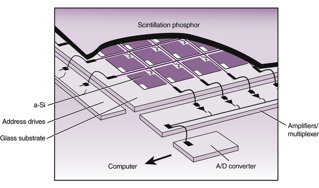
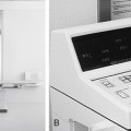
The detector system is usually dedicated to a single room and is permanently mounted in the table or upright Bucky system. Flat panel digital detectors are also available as mobile IRs and can be removed from the Bucky and used on the tabletop or a stretcher. After exposure, the digital image is available within a few seconds on a viewing monitor, and no separate reader unit is involved (Figure 6-11


Stay updated, free articles. Join our Telegram channel

Full access? Get Clinical Tree


