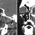
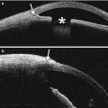
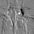
Fig. 3.1
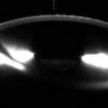
Clear cornea incision. Anterior segment OCT shows the scar (arrow) from a clear cornea incision in a patient who underwent cataract extraction with phacoemulsification

Fig. 3.2
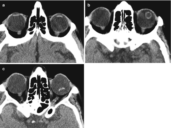
Lensectomy. The patient has a history of congenital cataract. Axial CT image (a) and axial T2-weighted MRI (b) show absence of the right crystalline lens, but intact left lens. Faint linear hypointense strands at the lensectomy site may represent residual portions of the capsular bag (arrow). There is staphylomatous deformity of both globes
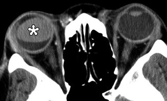
Fig. 3.3
Combined lensectomy, vitrectomy, and silicone oil injection. Axial CT image shows the hyperattenuating silicone oil floating within the left globe and absence of the intraocular lens
3.3 Lensectomy with Intraocular Lens Implant (Pseudophakia)
Cataract extraction with implantation of an artificial intraocular lens (IOL) implant is the currently accepted treatment for symptomatic cataracts, other than the situations delineated in the previous section. Although there are several different designs that are commercially available, the basic components of an IOL implant include the central optic portion and two haptics that hold the device in position (Fig. 3.4). The haptics can be configured as open versus closed loops. IOL implants are composed of polymethyl methacrylate (PMMA), polypropylene (Prolene), silicone, water-compatible polyhydroxyethyl methacrylate (hydrogel), or polyethylene (Dacron). Most rigid IOL optics are composed of PMMA, and the haptics are composed of either PMMA or Prolene, while flexible (foldable) IOLs are composed of either silicone or polyhydroxyethylmethacrylate (PHEMA). Following lens extraction, an IOL can be inserted either into the anterior chamber or the posterior chamber. Posterior chamber IOL insertion is now performed much more commonly than anterior chamber insertion for cataract surgery. The optic and haptics of posterior chamber IOL implants are located behind the iris and are supported by the residual capsule of the lens or by haptics positioned in the ciliary sulcus, just anterior to the ciliary process. The haptic loops maintain the position of the IOL and prevent the lens from dislocating and eventually become encased and secured by fibrous tissue. Anterior chamber IOL surgery is technically more straightforward than posterior chamber implantation, but has been associated with a relatively high complication rate, particularly when rigid IOLs were used. Nevertheless, indications for anterior chamber IOL include lens dislocation, loss of posterior capsular support during surgery, and selected cases of secondary implantation. After phacoemulsification and foldable IOL implantation, UBM typically reveals shifting of the iris posteriorly, deepening of the anterior chamber, and widening of its angle by approximately 10°.
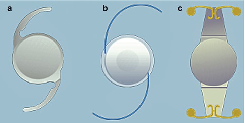

Fig. 3.4
Schematic of different types of intraocular lens implants, including Technis IOL (a), ReZoom (b), and Crytalens (c)
Only the optic component of the IOL implant is perceptible on CT or MRI. In fact, cross-sectional diagnostic imaging of cases with IOLs can be mistaken for aphakia if the section thickness is not small enough, such that partial volume averaging obscures the pupillary opening. Otherwise, the optic portion of an IOL appears as a thin linear hyperattenuating structure in the anterior portion of the globe on CT (Fig. 3.5). IOL implants are MRI compatible. Indeed, no significant displacement has been detected with IOL implants tested at 7 T MRI. However, magnetic susceptibility artifact may be observed with IOL implants that contain a platinum component (Worst Platinum Clip IOL implant) at high field strengths. The optic portion of IOL implants can be delineated on MRI as hypointense linear structures and is most conspicuous on T2-weighted sequences (Fig. 3.6). IOL implants do not enhance since they are impermeable to vascular ingrowth. The IOL implants and surrounding anatomy can be depicted in greater detail on UBM and OCT (Fig. 3.7).
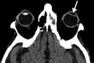
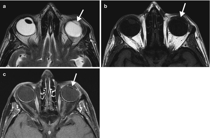
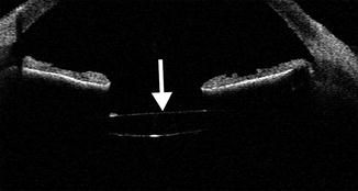

Fig. 3.5
Posterior chamber IOL implant depicted on CT. Axial CT image shows a hyperattenuating linear IOL implant (arrow) situated posterior to the expected plane of the iris. Compare the IOL implant to the normal native right lens

Fig. 3.6
Posterior chamber IOL implant depicted on MRI. Axial T2-weighted (a), T1-weighted (b), and fat-suppressed post-contrast T1-weighted (c) MR images show the non-enhancing hypointense implant (arrows). Compare the IOL implant to the normal right native lens, which is also hypointense

Fig. 3.7
Posterior chamber IOL implant depicted on OCT. The anterior chamber OCT image shows an IOL implant (arrow) that appears as a hyperreflective line located posterior to the iris
3.4 Phakic IOL Implantation
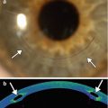
Phakic IOL (PIOL) implantation is effective for correcting myopia and myopic astigmatism. The procedure consists of securing an IOL, such as Veriflex or Verisyse, to the iris, while preserving the native lens intact. The anterior chamber IOL implant and its insertion site onto the iris can be readily delineated on UBM or OCT (Fig. 3.8), which can provide additional details about the anterior segment anatomy than slit lamp examination. In cases of high myopia of −8 diopters or more, PIOL implants can provide superior visual outcome compared with keratorefractive surgeries and a lower risk of complications than refractive lens exchange. Nevertheless, long-term postoperative follow-up examinations, including imaging with OCT or UBM, are useful to monitor for and prevent complications.
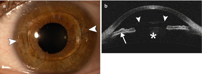

Fig. 3.8
PIOL implant. The patient has a history of high myopia treated with a Veriflex PIOL. Slit lamp photograph (a) shows the anterior chamber IOL implant with closed haptic loops that are fixated to the iris at approximately 3 and 9 o’clock positions (arrowheads). Anterior chamber OCT (b) shows the anterior chamber IOL implant (arrowheads), the insertion of the IOL in the iris (arrow), and the natural crystalline lens (Courtesy of Rebecca Tudor)
3.5 Piggyback Intraocular Lens Implantation (Polypseudophakia)
The piggyback technique was first described by Gayton in 1993 and consists of implanting two or sometimes more intraocular lenses in one eye. The implants can be inserted together into the capsular bag, or the addition IOL implant can be positioned in the ciliary sulcus. The piggyback technique is indicated to treat high hyperopia (in which a single high-power IOL implant would not have provided sufficient power), pseudophakic refractive errors (using minus-power IOL implants, the technique can benefit even myopic pseudophakia), and to correct the often high refractive errors of pseudophakic-penetrating keratoplasty patients, for whom lens exchange presents even more risk. The increased depth of focus provided by piggyback IOL implants is attributable to a contact zone between the lenses. A unique complication of the piggyback IOL implants is interlenticular cellular growth with resultant hyperopic shift, opacification, and loss of vision. This tends to be a late complication associated with IOL implants located together within the lens capsular bag and implants that are composed of hydrophobic acrylic. OCT, UBM, and Pentacam-Scheimpflug imaging can adequately delineate the components of piggyback IOL implants (Fig. 3.9).
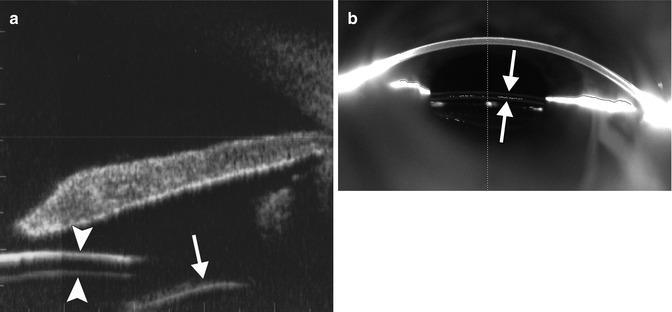

Fig. 3.9
Piggyback intraocular lens implantation. UBM image (a) shows two stacked IOL implants within the ciliary sulcus (arrowheads). The capsular bag (arrow) is located posterior to the implants. Pentacam-Scheimpflug image (b) also shows the two piggyback IOL implants in position (arrows) (Courtesy of Michael Amon MD)
3.6 Complications
Several complications related to cataract surgery and IOL implantation can be depicted on the various diagnostic imaging modalities. These include the presence of retained lens fragments, IOL implant dislocation, formation of dystrophic calcifications associated with IOL implants, and bullous keratopathy. Some of these complications can lead to additional morbidity and prompt diagnosis through the use of imaging, and clinical examination can optimize patient outcome.
3.6.1 Retained Lens Fragments
Although the lens nucleus is readily fragmented and aspirated using modern phacoemulsification technique, complete removal of the lens cortex can be difficult in certain patients without undue complications (e.g., rupture of the posterior capsular bag and vitreous loss). Retained lens fragments in the peripheral anterior segment can result in inflammation and glaucoma and are best delineated via OCT or UBM (Fig. 3.10). In patients that do not respond to topical or oral medications, additional anterior segment surgery to remove retained lens fragments may be necessary. If a rupture of the posterior capsule occurs, then nuclear or cortical fragments may fall into the vitreous cavity. This phenomenon can often be adequately depicted on B-mode ultrasound, in which there is echogenic material present within the otherwise anechoic or hypoechoic vitreous (Fig. 3.11). The incidence of posteriorly displaced lens fragments ranges between 0.3 and 1.1 %. These fragments can be removed with pars plana vitrectomy.
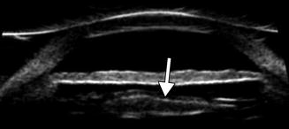


Fig. 3.10
Residual lens cortex in the anterior segment. UBM image of residual echogenic lens cortex peripherally (arrow) under the iris (Courtesy of Karen Capaccioli and Lois Hart)

Fig. 3.11
Residual lens cortex in the vitreous body. B-scan ultrasound image demonstrates the detached echogenic residual lens cortex in the vitreous cavity (arrow) (Courtesy of Karen Capaccioli and Lois Hart)
3.6.2 IOL Implant Dislocation
Implant dislocation may occur in the absence of appropriate capsular or zonular support or following traumatic injury to anterior ocular tissues and can be characterized as either in the bag or out of the bag, with correspondingly different etiologies. The most common in-the-bag etiologies are pseudoexfoliation and prior vitreoretinal surgery. The most common out-of-the-bag etiology is capsular rupture during cataract surgery. Retinal detachment is an important comorbidity associated with dislocated IOLs, affecting approximately 6 % of cases. Both MRI and CT scan depict gross displacement of the dislocated IOL implant (Fig. 3.12). These modalities may be obtained to rule out etiologies for patients who present with “vision changes” that are not necessarily related to the IOL implant, such as stroke or tumor along the visual pathway, and implant dislocation may be incidentally discovered on these exams. However B-mode ultrasound may be more appropriate for dedicated evaluation of distant out-of-the-bag implant dislocation and the condition of the retina (Fig. 3.13). UBM and OCT are valuable tools for more subtle changes in implant positioning in the anterior segment, providing the necessary visualization of the errant optic and haptic components and affected surrounding soft tissues. For example, slightly subluxated or tilted implants within the anterior segment can cause inflammation and even perforation of the iris as well as scarring of the cornea if these structures are chronically impacted by the implant. These changes can be depicted on UBM and OCT (Figs. 3.14 and 3.15). Furthermore, UBM and OCT are useful for confirming the presence of haptic-induced uveitis-glaucoma-hyphema syndrome, which can otherwise be difficult to evaluate on direct slit lamp evaluation due to opacification of the anterior chamber (Fig. 3.16). In particular, the offending haptic can be in contact with the iris pigment epithelium, the pars plicata, or have prolapsed into the angle recess near a filtration bleb internal ostium. Alternatively, while the haptic portion of the implant may not be obviously in contact with the affected iris or cornea at the moment of imaging, the presence of malalignment may serve as sufficient evidence, since the implant may still be freely mobile.

