Fig. 5.1
Periorbital injectable fillers used for malar and temporalis augmentation. Axial fat-suppressed T2-weighted MR images (a–c) show streaky areas of high signal within the periorbital soft tissues, which correspond to the filler material (arrows). These were incidental findings on the MRI, which was performed for other reasons
5.3 Punctal Plugs
Punctal and canalicular plugs are small devices used to occlude the lacrimal outflow system for treatment of dry eye syndrome and after surgical procedures such as penetrating keratoplasty or refractive surgery. A variety of plugs are available, including those composed of collagen, hydrogel, and silicone (Fig. 5.2). The silicone punctual plugs are radio-opaque (Fig. 5.3) and visible on radiographs, which can be used to localize the plugs if there is clinical uncertainty. The plugs should be appropriately recognized on radiographs so as to not mistake them for metal foreign bodies when screening patients prior to MRI.
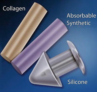
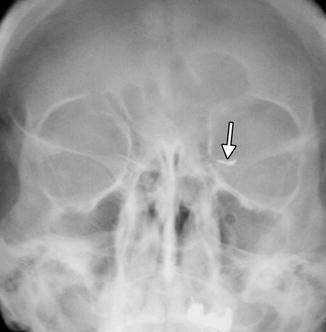
Fig. 5.2
Illustration of different types of commercially available punctual plugs (Courtesy of I-med Pharma, Inc)
Fig. 5.3
Punctal plug. Frontal radiograph shows a radio-opaque linear structure projecting at the expected location of the left inferior lacrimal punctum and canaliculus (arrow)
5.4 Eyelid Weights
Facial nerve deficits can lead to keratitis secondary to lagophthalmos, eyelid retraction, and incomplete blink. Implantation of eyelid weights in the upper eyelid as a procedure for addressing this condition was introduced in 1958 by Illig. Platinum or gold weights are available in different sizes and shapes, including thin profile (Fig. 5.4). Standard sizes range from 0.6 to 1.8 g. The implants are contoured to fit the curvature of the globe and contain holes for fixation to the tarsus with sutures, which can be identified on plain radiographs (Fig. 5.5). Ingrowth of fibrous tissue through the holes also helps secure the weight in position. Flexible chains have also been designed to optimally match the curvature of the tarsal plate of the upper eyelid. Eyelid weights are typically implanted between the orbicularis oculi muscle and the tarsal plate and secured to the tarsus in the upper eyelid, enhancing upper eyelid excursion. The eyelid weights generally produce considerable streak artifact on CT, which can obscure surrounding anatomy (Fig. 5.6). Platinum and gold eyelid weights are considered MRI compatible but may also cause susceptibility effects that limit the visualization of surrounding structures (Fig. 5.7). Complications related to eyelid implantation include prominent implants visible through the skin, infection, allergic reaction, migration, and extrusion. Ultimately, the eyelid weight may be removed if sufficient facial nerve function is recovered.
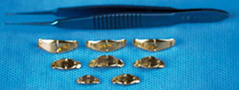
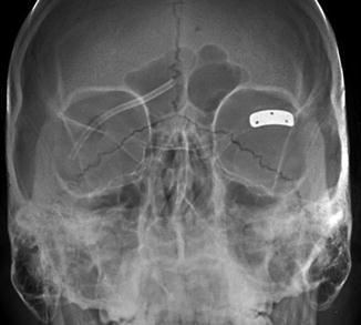
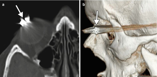
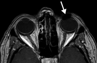
Fig. 5.4
Photograph of various sizes of gold eyelid weight implants (Courtesy of Osmed)
Fig. 5.5
Eyelid weight depicted on radiography. Frontal radiograph shows a rectangular, curved metal implant containing three holes for suture fixation at the level of the left upper eyelid
Fig. 5.6
Eyelid weight depicted on CT. The axial (a) and 3D CT (b) images show extensive streak artifact associated with the device (arrows)
Fig. 5.7
The fat-suppressed post-contrast T1-weighted MRI shows that the presence of the eyelid weight (arrow) results in mild field inhomogeneity from metal artifact that obscures surrounding structures
5.5 Eyelid Springs
Eyelid (palpebral) springs are infrequently used to augment lid closure in patients with eyelid paralysis. The device is implanted via orbitotomy and consists of a palpebral branch and an orbital branch connected by a spring mechanism at the fulcrum (Fig. 5.8). The spring mechanism is sutured to the periosteum of the lateral orbital rim. The positioning and function of the device can be assessed on radiographs obtained in the open and closed lid positions, whereby the palpebral branch is expected to descend with lid closure (Fig. 5.9). This does not occur, however, if the device has been deactivated. The eyelid spring in relation to the soft tissues of the orbit can be better depicted on CT, however (Fig. 5.10). Potential complications include dislocation, metal fatigue resulting in failure, and exposure.
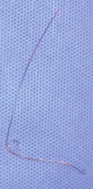
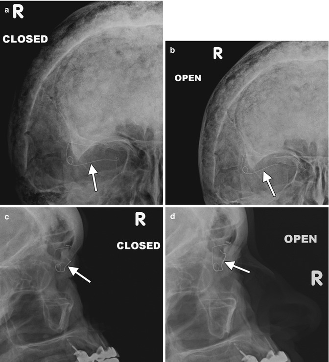
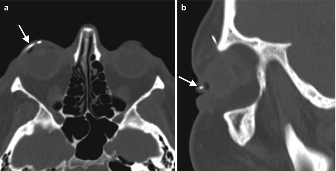
Fig. 5.8
Photograph of an eyelid spring (Courtesy of Dawn DeCastro MD)
Fig. 5.9
Eyelid spring on dynamic radiographic imaging. Open and closed frontal and lateral radiographs (a–d) show the lower arm of the device (arrows) moves with the eyelid
Fig. 5.10
Eyelid spring depicted on CT. Axial (a) and sagittal (b) CT images show the inferior limb of the spring positioned within the upper lid (arrows)
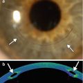
5.6 Lateral Canthotomy, Cantholysis, and Canthopexy
Lateral canthotomy and cantholysis is a procedure used to treat orbital compartment syndrome in the setting of acute orbital hemorrhage or other conditions causing high orbital pressure such as carotid cavernous fistula. It is also used as a surgical approach to the lateral orbit. The procedure involves incising the lateral canthus of the eyelids and releasing one or both lateral canthal tendons. On imaging, disruption of one or both lateral canthal tendons can be discerned, and increased proptosis and herniation of orbital contents may be observed after the procedure (Fig. 5.11). Canthopexy, on the other hand, consists of repairing or reattaching the canthal tendons. Occasionally metallic anchors, such as wire or screws, may be used to affix the ligament to the underlying bone, which should not be mistaken as an unintended foreign body on imaging (Fig. 5.12).
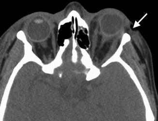
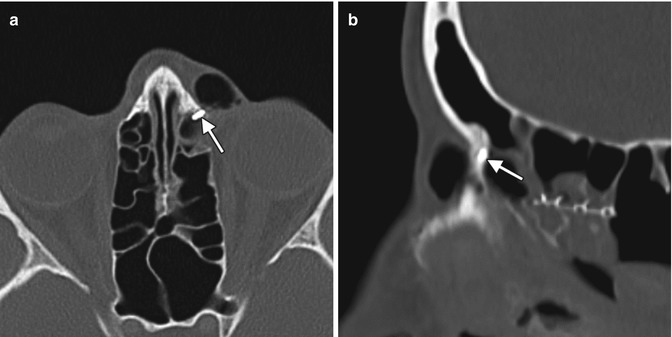
Fig. 5.11
Lateral canthotomy and cantholysis. Axial CT image shows a surgical defect in the left lateral canthal region (arrow) with mild anterior herniation of orbital fat and proptosis
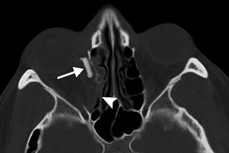
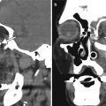
Fig. 5.12
Canthopexy with Mitek anchor. Axial (a) and sagittal (b) CT images show a metallic density structure embedded within the left frontal process of the maxilla (arrows)
5.7 Orbital Tissue Expanders for Congenital Anophthalmia
Congenital or acquired anophthalmia in pediatric patients has significant cosmetic ramifications. In particular, growth of the orbit during early childhood is dependent on the presence and growth of the orbital contents. If untreated, an anophthalmic socket in a young child will result in a disproportionately small orbit and sometimes entire hemifacial bone structure compared to the contralateral side. Traditional methods for orbital expansion include using progressively enlarging static acrylic conformers, insertion of conventional static spherical orbital implants, dermis-fat grafts, or inflatable balloon expanders for orbital enlargement. However, these techniques may still result in suboptimal cosmetic outcomes, with delayed growth of the bony orbit and overlying soft tissues. Another option for stimulating bone growth in an anophthalmic socket is an integrated orbital tissue expander comprised of an inflatable silicone globe on a sliding titanium T-plate secured to the lateral orbital rim with screws (Fig. 5.13). The sphere can be inflated via transconjunctival injection of saline. Saline expanders appear as spherical sacs containing fluid attenuation on CT adjacent to the metal density T-plate (Fig. 5.14). Hydrogel tissue expanders are an alternative therapy for the anophthalmic socket. The expanders are inserted in a dry, contracted state and expand gradually to full size via osmosis of fluid from surrounding tissues, with up to a tenfold increase in volume. Hydrogel orbital expanders are available in the form of spheres and hemispheres (Fig. 5.15). Hydrogel expanders appear as nearly fluid attenuation on CT due to the high water content. On MRI, these devices tend to display low T1 signal and high T2 signal, and do not enhance (Fig. 5.16). The increased orbital volume provided by the use of these devices can be delineated on imaging.
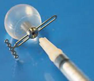
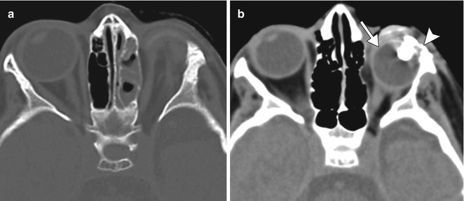
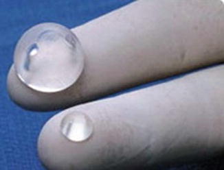
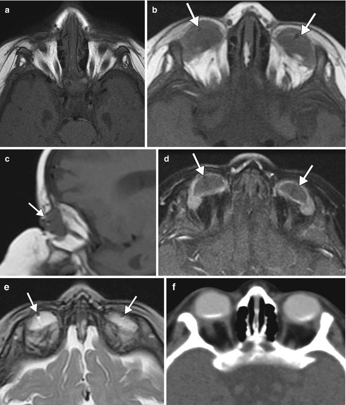
Fig. 5.13
Photograph of a saline orbital sphere, which consists of an inflatable silicone sphere held in place by a titanium bone plate anchored to the lateral orbital wall by screws with a slotted arm attached to the bone plate, providing multiple fixation areas. This allows for repeated fixation adjustments as the orbit enlarges (Courtesy of Innovia LLC)
Fig. 5.14
Saline orbital expander. Preoperative axial CT image (a) shows a small left orbit. Postoperative axial CT image (b) shows a saline-filled left orbital expander (arrow) attached to the lateral orbital rim via the metal plate (arrowhead) (Courtesy of David Tse MD)
Fig. 5.15
Photograph of hydrogel hemispheric implants shows the degree to which the implants can expand. The material can be used to increase the orbital volume prior to permanent orbital implant insertion (Courtesy of Osmed)
Fig. 5.16
Hydrogel orbital expander. Preoperative axial T1-weighted MRI (a) shows bilateral anophthalmos. Axial (b) and sagittal (c) T1-weighted, axial post-contrast T1-weighted (d), and axial T2-weighted (e), and MR images show bilateral hemispherical hydrogel expanders in position (arrows). The expanders have signal characteristics similar to fluid. Subsequent axial CT image (f) shows interval placement of bilateral orbital implants
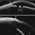
5.8 Evisceration, Enucleation, and Exenteration
When there is otherwise untreatable disease, it may become necessary to remove the eye or the entire orbital contents. The surgical options include evisceration, enucleation, and exenteration.
Evisceration consists of removing the globe contents while preserving the sclera and attached extraocular muscles (Fig. 5.17). Occasionally, the cornea may be retained. Indications include endophthalmitis or a blind, painful eye due to a known etiology that would not be exacerbated by incomplete excision. The residual sclera can be discerned on CT and MRI. A spherical implant is often inserted within the residual sclera (Fig. 5.18). Alternatively, the scleral cavity may be filled with a dermis-fat graft (Fig. 5.19). Dermis fat graft placement is sometimes performed after complications related to initial placement of a synthetic implant. After proper healing, a prosthetic shell may be made to cover the socket and cosmetically match the contralateral eye.
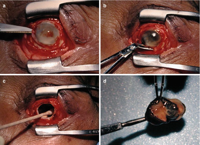
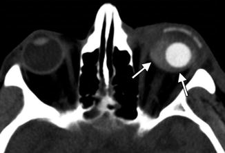
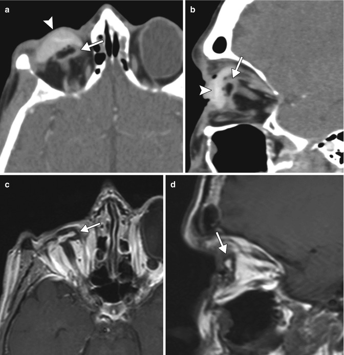
Fig. 5.17
Evisceration surgery. The patient has a history of endophthalmitis. Intraoperative photograph after circumferential conjunctival peritomy shows the anterior chamber is entered with a blade (a); the cornea is removed (b); the sclera is emptied of its contents and cleaned with absolute alcohol (c); the infected intra-ocular contents have been removed (d)
Fig. 5.18
Evisceration with intrascleral implant. Axial CT image shows a left evisceration socket containing a small spherical implant and hyperattenuating fluid that outlines the surrounding sclera (arrows)
Fig. 5.19
Eviscerated sclera without orbital implant. Axial (a) and sagittal (b) CT images and axial (c) and sagittal (d) post-contrast T1 MRI images show the partially collapsed residual sclera within the right orbit (arrows). A scleral shell prosthesis is present on the CT (arrowheads) but absent on the MRI
Enucleation consists of removing the entire globe (Fig. 5.20). Indications for enucleation include a blind painful eye, intraocular tumor, trauma with risk of sympathetic ophthalmia, phthisis bulbi, microphthalmia, and panophthalmitis. The extraocular muscles may be imbricated in front of an orbital implant, sutured directly to the orbital implant or to the wrapping surrounding the implant, or, less commonly, allowed to fall back into the orbit. The orbital implant and wrapper may be made from a variety of materials, which are described below. As with evisceration, a prosthetic shell is usually made to cover the socket. Rarely, a shell may be used alone without an orbital implant filling the socket, particularly if a complication necessitated removal of the implant (Fig. 5.21).
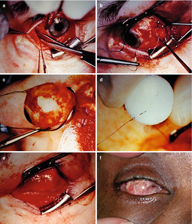
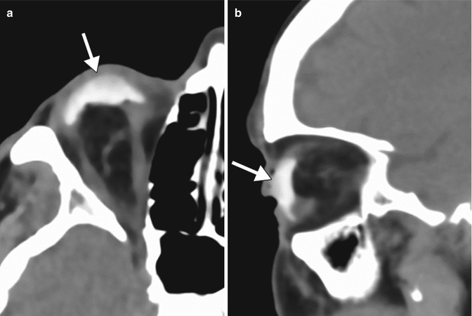
Fig. 5.20
Enucleation procedure. Photograph shows conjunctiva is being opened 360° to expose globe and extraocular muscles (a). Each extraocular muscle is isolated, sutured, and detached from the globe (b). The globe is removed from the orbit after the optic nerve has been transected (c). Extraocular muscles are sutured to implant (d). Tenon’s capsule and conjunctiva are closed anterior to the implant (e). A well-healed anophthalmic socket with clear plastic conformer is shown in a different patient (f)
Fig. 5.21
Orbital prosthesis without orbital implant after enucleation. Axial (a) and sagittal (b) CT images show a hyperattenuating ocular prosthesis (arrows) supported by orbital fat after enucleation
Several types of orbital implants may be used after evisceration and enucleation. These can be composed of a variety of materials (Table 5.1) and are available in different shapes and sizes (Figs. 5.22, 5.23, 5.24, 5.25, 5.26, and 5.27). For example, implants may feature grooves for the extraocular muscles or have ovoid configurations that were designed to conform better to the enucleation cavity than standard spherical implants. Furthermore, the implants may be fitted with motility pegs that couple the ocular prosthesis with the ocular implant in order to optimally synchronize and transmit motion to the prosthesis when the extraocular muscles move the implant. These motility pegs have fallen out of favor in recent years because of frequent complications. MRI has a specific role in the evaluation of ocular implants for motility pegs; it serves to confirm sufficient fibrovascular ingrowth of the implant in order to accommodate the peg. Although modern implants are generally composed of hydroxyapatite, porous polyethylene (Medpor), and silicone, older implants composed of plastic, acrylic, glass, and metal may still be encountered on imaging (Fig. 5.28). Regardless of the implant type, signal changes within the optic nerve remnant on T2-weighted images and atrophy of the nerve remnant and the chiasm are to be expected following enucleation and should not be interpreted as necessarily indicating active pathology (Fig. 5.29).
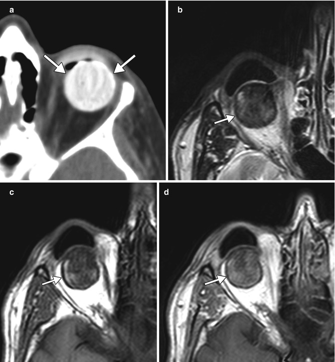
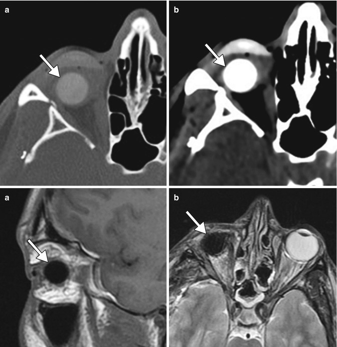
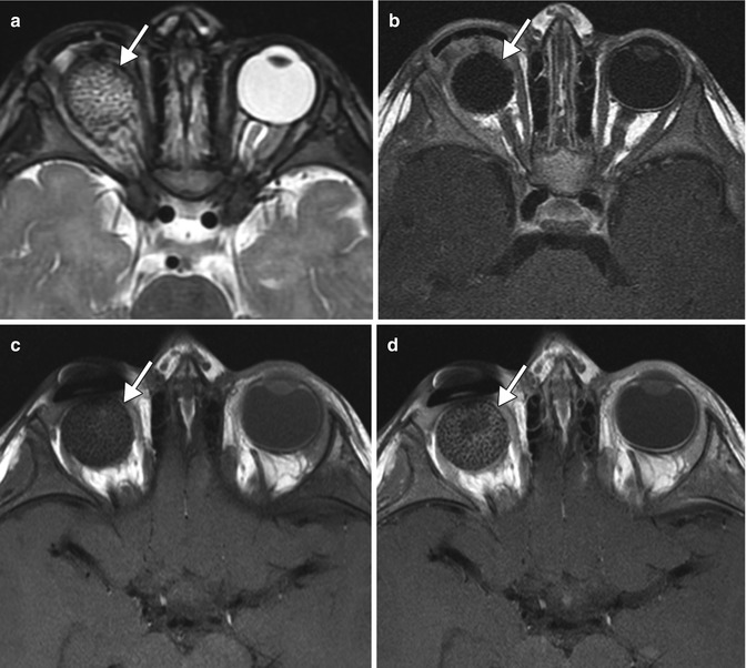
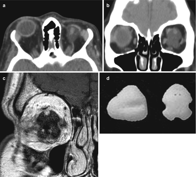
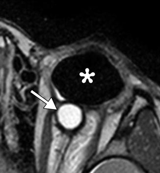
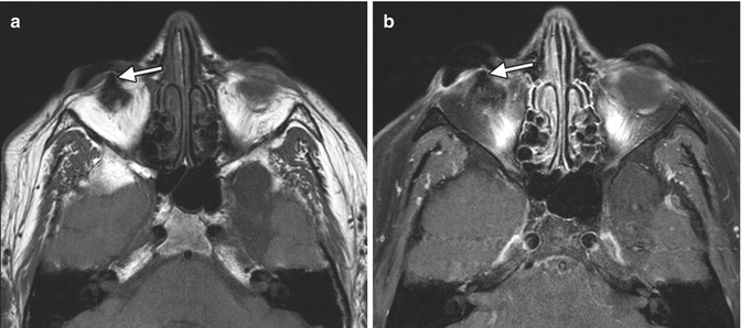
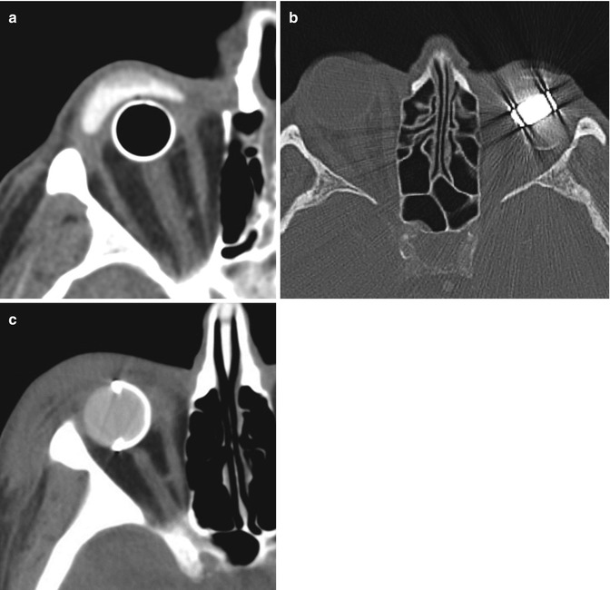
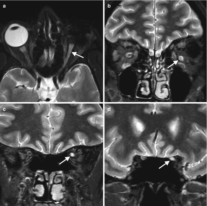
Table 5.1
Imaging features of commonly used orbital implant materials
Material | CT | MRI |
|---|---|---|
Hydroxyapatite andaluminum hydroxide ceramic | Hyperattenuating, similarto cortical bone | Low to intermediate signal on T1 and T2. Enhancement may occur with fibrovascular ingrowth |
Silicone | Hyperattenuating but to a lesserdegree than hydroxyapatite | Very low signal on T1 and T2 |
Porous polyethylene (Medpor) | Attenuation intermediatebetween fat and water | Low signal on T1 and high on T2. Enhancement after fibrovascular ingrowth |
Fig. 5.22
Hydroxyapatite orbital implant after enucleation surgery. Axial CT image (a) shows a hyperattenuating spherical left implant (arrows). Axial T2-weighted (b), T1-weighted (c), and post-contrast T1-weighted (d) MR images in a different patient show that the hydroxyapatite implant (arrows) displays low to intermediate signal and mild enhancement
Fig. 5.23
Silicone orbital implant after enucleation surgery. Axial CT images in the bone (a) and soft tissue (b) windows show hyperattenuating right ocular implant (arrows) and prosthesis. The implant (arrows) displays low signal on both T1-weighted (c) and T2-weighted (d) MRI. The prosthesis is not present on the MRI
Fig. 5.24
Medpor ocular implant after evisceration. Initial axial T2-weighted (a) and post-contrast T1-weighted (b) MR images show a non-enhancing spherical right ocular prosthesis (arrows). Axial pre-contrast (c) and post-contrast (d) T1-weighted MR images obtained 6 months later show interval enhancement in the periphery of the prosthesis (arrows), indicating fibrovascular ingrowth
Fig. 5.25
Conical Medpor orbital implant. Axial (a) and coronal (b) CT images show longitudinal groves for the rectus muscles along the sides of the implant in the left orbit. Coronal T1-weighted MRI (c) shows multiple grooves in the right ocular implant. Front and side photographs of the conical Medpor implant (d)
Fig. 5.26
Oval ocular implant. Axial T2-weighted MRI shows a left silicone implant (*) in a patient with anophthalmia. A cyst is present posterior to the implant (arrow)
Fig. 5.27
Orbital implant with motility peg. Axial T-weighted (a) and post-contrast T1-weighted (b) MR images show the low signal peg extending from the enhancing implant (arrows). Peg placement allows the implant to be directly coupled to the prosthesis. The peg is drilled into the implant after fibrovascular ingrowth is confirmed on MRI
Fig. 5.28
Obsolete orbital implants. Axial CT image shows a hollow metal spherical implant and overlying hyperattenuating shell prosthesis in a patient who underwent enucleation in 1964 for trauma (a). Axial CT image shows a left orbital implant that consists of both plastic and metal components with considerable streak artifact (b). Axial CT image shows a hyperattenuating ocular implant with a hemispheric metal shell, which was placed after enucleation for trauma to the right globe during the Vietnam War (c)
Fig. 5.29
Optic nerve changes after enucleation. Axial (a) and coronal (b–d) MRI show that the optic nerve ipsilateral to the enucleated eye (arrows) is atrophic and displays T2 hyperintense signal compared to the normal contralateral optic nerve, an expected finding after enucleation
Orbital exenteration is a radical procedure that involves removal of the globe and orbital contents (Fig. 5.30). The eyelids may be spared, depending on the pathology. Indications include cutaneous or conjunctival malignancies with orbital invasion, orbital or lacrimal gland malignancies, or orbital mucormycosis. Reconstructive techniques include ipsilateral temporalis muscle flaps, cutaneous or myocutaneous free flaps, and osseointegrated implants. Often the socket is left to granulate or is lined with a split-thickness skin graft, which allows for direct surveillance for recurrent disease.
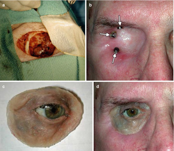
Fig. 5.30
Exenteration procedure with orbital prosthesis. Photograph (a) shows entire contents removed from the right orbit with split-thickness skin graft ready for placement. Photograph (b) shows the fully healed, skin-covered exenteration socket with endosseous magnetic implants (arrows) used to secure the orbital prosthesis. Photograph (c) shows the orbital prosthesis consisting of an artificial eye and adnexal structures. Photograph (d) demonstrates the orbital prosthesis in position, providing a satisfactory cosmetic result, especially if covered with large-framed spectacles
Diagnostic imaging can be helpful for evaluating certain complications that may occur following evisceration, enucleation, and exenteration. Postoperative hemorrhage into the enucleation cavity may appear as hyperattenuating fluid outlined by the residual sclera (Fig. 5.31). Postoperative infection is particularly a concern when surgery is performed in the setting of preexisting endophthalmitis or panophthalmitis. On imaging, abnormal fluid collections, gas, fat stranding, and enhancement may be encountered within the enucleation cavity (Fig. 5.32). Likewise, infected fluid collections can form around the implants and prostheses (Fig. 5.33). In the setting of exenteration for rhino-orbitocerebral zygomycosis, serial imaging may show the need for repeated radical debridement. Nevertheless, this condition carries a poor prognosis due to complications such as arteritis and cerebral infarction (Fig. 5.34). Postoperative conjunctival dehiscence resulting in exposure of the orbital implant may result from inflammation or infection or improper selection of the orbital implant size. Although implant extrusion may be clinically apparent, imaging is useful for evaluating associated problems (Fig. 5.35). Finally, the stigmata of postenucleation/evisceration socket volume loss can be encountered on diagnostic imaging. This syndrome is fairly common and consists of enophthalmos, deepening of the superior sulcus, tilting of the prosthesis, and sinking of the implant (Fig. 5.36). Correction of anophthalmic enophthalmos can be achieved using injectable filler agents, such as calcium hydroxyapatite and hyaluronic- or collagen-based gels.
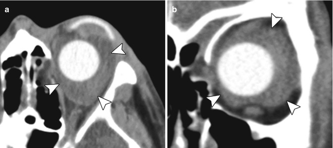
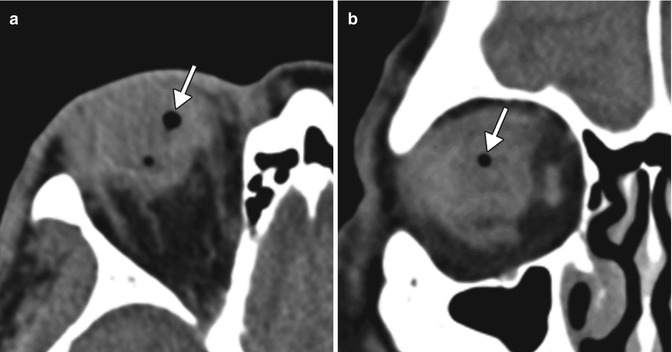
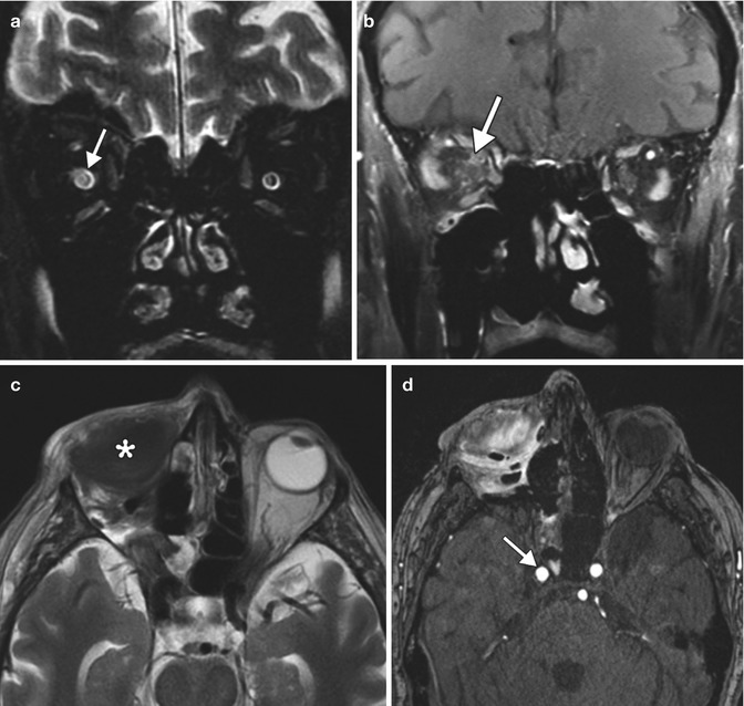
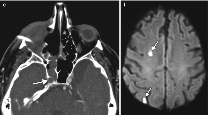
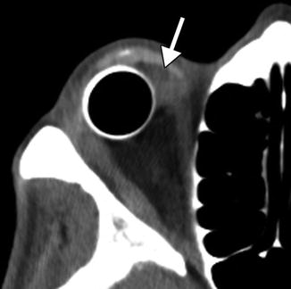
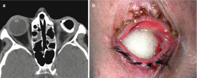
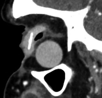
Fig. 5.31
Orbital hemorrhage after enucleation. Axial (a) and coronal (b) CT images show fluid within orbit surrounding the silicone ocular implant (arrowheads)
Fig. 5.32
Infection after evisceration. Axial (a) and coronal (b) CT images show gas (arrows) and fluid within the eviscerated right sclera. There is also stranding of the surrounding orbital fat
Fig. 5.33
Exenteration for rhino-orbitocerebral mucormycosis. Initial coronal T2-weighted (a) and post-contrast T1-weighted (b) MR images show abnormal enhancement in the right orbital apex and high T2 signal within the right optic nerve (arrows). Initial postoperative axial T2-weighted (c) image shows right orbital exenteration with myocutaneous flap (*). The concurrent time-of-flight MRA (d) shows that the right carotid artery is still patent (arrow). Follow-up axial CTA (e) obtained one week later shows opacification of the right sphenoid sinus and new occlusion of the right internal carotid artery (arrow). DWI (f) shows small areas of acute infarction in the right cerebral hemisphere watershed zones (arrows)
Fig. 5.34
Peri-implant infection. The patient presented with purulent discharge from the right eye socket. Axial CT image shows a fluid collection (arrow) between the ocular implant and prosthesis
Fig. 5.35
Ocular prosthesis exposure. Axial CT (a) shows deficiency of soft tissue anterior to the left ocular prosthesis. Chronic left orbit inflammatory changes are also present. Clinical photograph (b) in another patient shows the porous implant exposed through a melted conjunctiva. Although exposure is obvious on clinical exam, radiological imaging can help assess for potential etiologies
Fig. 5.36
Postenucleation socket with significant orbital volume loss. The sagittal CT image shows enophthalmos, deepening of the superior sulcus, tilting of the prosthesis, and sinking of the implant
5.9 Orbital Foreign Body Removal
Prompt detection and accurate localization of intraorbital foreign bodies are crucial for the optimal management of patients. Computed tomography (CT) is very useful in determining the size of foreign bodies and localizing them as intraocular, extraocular, or retro-ocular before, during, and after surgery if necessary. Metallic foreign bodies are readily recognizable on CT, although streak artifact can obscure surrounding structures. Plastic and wood foreign bodies may be less conspicuous on CT. In particular, wood can mimic air on CT. CT is generally considered the gold standard in the evaluation of foreign bodies because it is safe to use with metallic foreign bodies and it excludes orbitocranial extension and is also able to diagnose orbital wall fractures with high accuracy. CT is sometimes obtained after foreign body removal for verification (Fig. 5.37) and to assess potential complications such as orbital infection. However, many orbital foreign bodies, particularly those made of metal and those in posterior orbital locations, are not surgically removed. MRI is generally not recommended for the evaluation of the foreign bodies due to the risks associated with ferromagnetic metal.
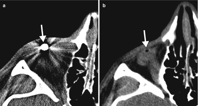
Fig. 5.37
Orbital foreign body removal. Preoperative CT image (a) shows a metallic foreign body in the anterior orbit (arrow). Postoperative CT image (b) shows interval absence of the metallic foreign body with a small amount of residual air (arrow)
5.10 Orbital Fracture Repair
A wide variety of materials can be used for orbital fracture repair (Table 5.2 and Figs. 5.38, 5.39, 5.40, and 5.41).
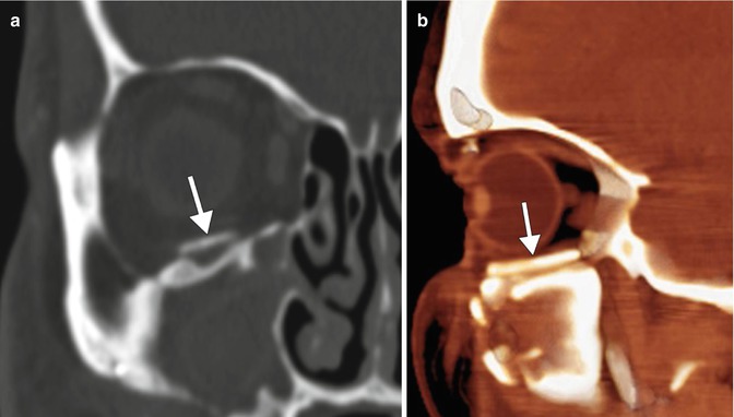
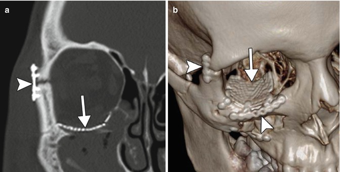
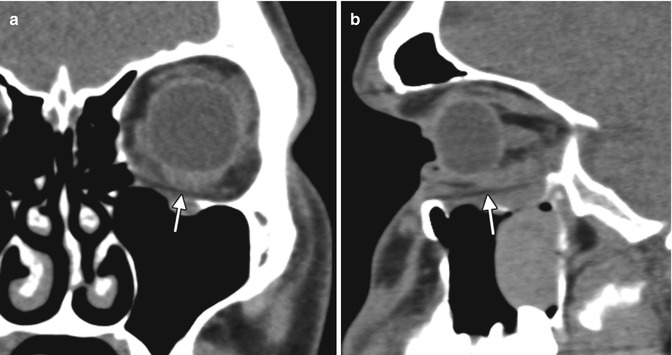
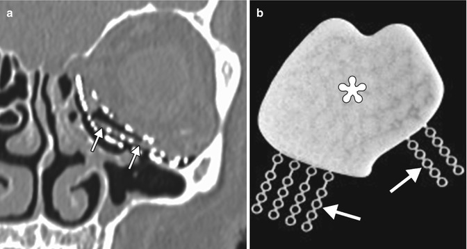
Table 5.2
Orbital wall reconstruction materials
Material | Properties | Imaging features |
|---|---|---|
Titanium, vitallium,stainless steel | Mesh may be shaped to fit contours of orbit | High attenuation on CT; generally MRI compatible |
Medpor | Vascularized via tissue ingrowth may resist infection and movement | Intermediate attenuation between soft tissue and fat on CT; low T1 signal and intermediate to high T2 signal on MRI |
Silicone | Smooth and easy to shape and place in orbit; cause fibrous capsule to form within weeks of implantation; do not become stabilized as well as porous implants; may have severe inflammatory reaction to material; at risk for capsular hemorrhage | Attenuation between soft tissue and bone on CT; low signal on MRI |
Resorbable | Various biodegradable materials, including polydioxanone sulfate | Nearly soft tissue attenuation on CT and low signal on MRI; the materials become less discernible over the course of months due to resorption |
Glass bioceramic | Individually prefabricated using computer-assisted design and manufacturing | Hyperattenuating on CT; low signal on all MRI sequences |
Composite | Porous polyethylene implants with embedded titanium provide a newer alternative for orbital reconstruction with a profile that combines several advantages of porous polyethylene and titanium implants | Different imaging characteristics for the components of the implant |
Fig. 5.38
Bone graft. Coronal CT image in the bone window (a) and colorized sagittal maximum intensity projection CT image (b) show bone positioned along the orbital floor (arrows)
Fig. 5.39
Titanium mesh plate. Coronal (a) and 3D volume-rendered CT (b) images show the mesh positioned along the floor of the right orbit (arrows). Miniplates and screws secure the orbital rim fractures (arrowheads)
Fig. 5.40
Medpor implant. Coronal (a) and sagittal (b) CT images show that the inferior orbital wall implant appears as a thin sheet with intermediate attenuation between soft tissue and fat (arrows)
Fig. 5.41
Medpor Titan implant. Coronal CT image (a) shows stacked layers of metallic mesh and lower attenuation Medpor component (arrows). Photograph (b) of a Medpor Titan implant comprising a sheet of Medpor with partially embedded titanium strips (arrows)
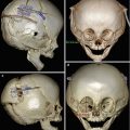
5.10.1 Orbital Wall and Rim Fracture Repair
The goal of managing orbital wall blow-in or blow-out fractures is to restore extraocular motility and orbital volume, which can be impacted by herniation of orbital contents, displaced bone fragments, and expansion of the bony orbit. Although postoperative imaging after orbital fracture repair is mainly performed to assess complications, some practitioners request CT to verify correct positioning of orbital sheet implants and reduction of fracture fragments in the early postoperative period. Medial orbital wall fractures may be associated with diplopia due to herniation or entrapment of the medial rectus muscle. In large medial orbital wall fractures, complete coverage of the posterior aspect of the fracture with the implant can be difficult, and CT may be useful to define the extent to which there is remaining deficiency of the lamina papyracea (Fig. 5.42). Orbital floor fractures in children often do not require reduction, since the flexible bone assumes a near-anatomic alignment. However, pediatric trapdoor fractures may require urgent treatment in order to prevent ischemia and permanent damage to the affected extra-ocular muscle. Orbital roof fractures that are associated with dural tears may require an intracranial approach, whereby fat, mesh, and/or fascial grafts are positioned over the orbital roof in order to reconstruct the defect and seal dural leaks (Fig. 5.43). Reconstructed orbital roof fractures sometimes have a flattened configuration, which can be associated with exophthalmos (Fig. 5.44). Superior orbital rim fractures associated with pneumatized frontal sinuses pose particular cosmetic and functional considerations. Along with restoring the proper orbital contour, it is also important to maintain the integrity of the frontal sinus to minimize the risk of infection and obstruction of secretions. Comminuted fractures of this region can be secured via absorbable or low-profile titanium mesh for optimal cosmetic results (Fig. 5.45). Finally, small residual displaced bone fragments in the orbits or paranasal sinuses associated with comminuted orbital fractures are not uncommonly encountered and are typically left in position after repair, since these are generally innocuous and resorb over time (Fig. 5.46). Likewise, paranasal sinus opacification from hemorrhage and inflammation during the early postoperative period generally resolves spontaneously, unless there is outflow obstruction.
 Introduction to Approaches and Modalities in Postoperative Orbital Imaging
 Imaging After Vitreoretinal Surgery
 Imaging After Cornea Surgery
 Imaging of Strabismus and Craniofacial Malformation Surgery
 Imaging After Orbital and Intraocular Oncology Therapies
 Ophthalmic Imaging and Neuroimaging of the Effects of Glaucoma Treatment


Related posts:
Introduction to Approaches and Modalities in Postoperative Orbital Imaging
Imaging After Vitreoretinal Surgery
Imaging After Cornea Surgery
Imaging of Strabismus and Craniofacial Malformation Surgery
Imaging After Orbital and Intraocular Oncology Therapies
Ophthalmic Imaging and Neuroimaging of the Effects of Glaucoma Treatment
Stay updated, free articles. Join our Telegram channel
Full access? Get Clinical Tree
