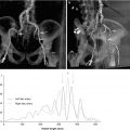
Fig. 28.1
Maximum intensity projection of a multidetector row CT angiogram demonstrating significant aortoiliofemoral calcific atheroma
Recent efforts to minimize the contrast volume to prevent contrast-induced nephropathy associated with aortoiliofemoral imaging have demonstrated feasibility and good image quality. These techniques employ direct injection of dilute contrast media in the infrarenal abdominal aorta [42]. In patients with severe renal insufficiency, non-contrast MRI scans can also image the aortoiliofemoral access sites [43].
In the presence of short segments of compliant artery, the femoral access site can have a smaller diameter than the intended sheath by 1–2 mm, as predicted by MDCT. A sheath-to-femoral-artery ratio of 1.05 or higher is predictive of vascular complications and an increased 30-day mortality [44]. Ultrasound is infrequently used for pre-procedural vascular assessment but may aid in evaluating access vessel characteristics and optimal puncture site at the time of the TAVR. It has been reported that as many as 33 % of patients with critical AS had unfavorable iliofemoral access, with more than three-fourths of those patients having a minimal luminal diameter <8 mm [45, 46]. Circumferential and horseshoe-type calcifications, in association with small and diseased iliofemoral vessels, represent contraindications to the TF approach. When access via the iliofemoral arteries is not possible, other routes are considered [47]. Severe aortic tortuosity may test the length and maneuverability of the TF-TAVR delivery system (Fig. 28.2).
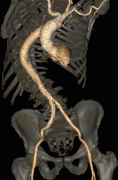

Fig. 28.2
Volume-rendered view of a multidetector row CT angiogram demonstrating significant tortuosity of the thoracoabdominal aorta
Assessment of Aorta and Peripheral Arteries: Root and Ascending
Aortic root structures, including their dimensions and morphology, are analyzed in detail for all TAVR candidates. In addition to contributing to selection of device type and size, analysis of the root and ascending aorta further contributes to selection of the delivery route. Various features of the root and ascending aorta—including valve cusps, degree and morphology of calcification and atheromatous disease, coronary ostial height, characteristics of the LV outflow tract (LVOT), and the interrelated geometry of these structures—may preclude the use of either TF- or TA-TAVR approaches [36]. These features are also predictive of, in some cases, procedural success and complications. Aortic annular sizing is discussed in detail in the next section.
Echocardiography and MDCT are used to evaluate the extent and locations of annular and leaflet calcifications. Severe calcification can result in acoustic shadowing with echocardiography [14] and renders CMR less suitable due to signal void in such cases. Consequently, MDCT is currently the favored modality for quantifying severity and location of root calcifications. The dimensions and morphology of the root can predict the likelihood of inadequate valve deployment, with consequent risks of paravalvular aortic regurgitation (PAR) and device embolism. The degree and pattern of calcification at the cusps and surrounding structures is also associated with PAR due to asymmetric valve expansion—such as might be the case in the presence of a densely calcified inter-trigonal area—in addition to catastrophic root rupture and cerebral or downstream embolism [48]. Aortic valve calcium scoring prior to TA-TAVR may play a role in predicting post-procedure PAR [49].
Coronary ostial height is assessed by a combination of echocardiography, CMR or MDCT, with a view to ensuring that device deployment will not compromise the coronary ostia from the device itself or displaced debris. TTE and particularly TEE can delineate the distance from the annulus to the right coronary ostium but is limited in detecting the annulus-to-left-coronary distance, which does not lie in a standard echocardiographic plane. Measurements from 3D echocardiographic datasets may be feasible in determining the height of the left coronary ostium.
MDCT provides a comprehensive assessment of coronary ostial height, with an average annulus-to-left-coronary distance of 13.4 ± 3.2 and an annulus-to-right-coronary distance of 13.6 ± 2.8 mm [50]. The distance between the left coronary cusp (LCC) and left coronary ostium is measured from oblique sagittal or coronal projections on MDCT [41]. While it is important to measure coronary ostial height to reduce the risk of ostial obstruction [47], no definite criteria exist to exclude patients on the basis of inadequate height. Nevertheless, a cutoff of 11–14 mm has been proposed, with a height <10 mm potentially suggesting a risk of ostial occlusion [47] (Fig. 28.3). The risk of coronary obstruction is felt to be higher in the setting of heavily and diffusely calcified valve cusps, low-left main height, and patient with narrow aortic sinuses. It is also important to integrate the valve characteristics with a patient’s individual anatomy. For example, valve height and its portions that are covered by a skirt of fabric are relevant to note, as excessively high deployment can interfere with coronary flow (Fig. 28.4).
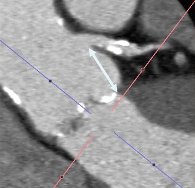
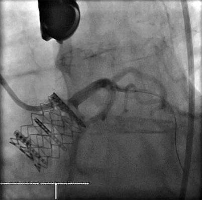

Fig. 28.3
Multiplanar reformat of a multidetector row CT angiogram demonstrating the height from the aortic leaflet insertion point to the left main artery (double headed arrow)

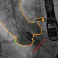
Fig. 28.4
Fluoroscopic projection demonstrating high valve deployment
The angulation of the aortic root with respect to the body axis is critical to assess prior to implant. This is done to ensure precise coaxial positioning of the device along the centerline of the aortic annular plane [41]. Because of significant variability in patient anatomy, pre-procedural assessment of root geometry can be helpful in predicting the angle of implant. Traditionally, the orientation of the root has been assessed angiographically, with repeated contrast injections. More recently, MDCT-based reconstructions have been valuable in pre-procedural prediction of the root angle [45, 51]. This has the potential to reduce intra-procedural times, as well as radiation and contrast doses.
Annulus Sizing
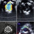
The anatomy of the aortic valvar complex has become a subject of revived interest since the development of TAVR as a viable therapy. Emphasis has been placed on the elliptical (rather than circular) nature of the aortic annulus, and its impact on annular measurement and valve sizing. By definition, the annulus is taken as the virtual inferior basal ring measured in systole. An oval shape of the aortic annulus can be appreciated with 3D modalities (3D ECHO, CMR, MDCT), and in approximately 50 % of patients, the mean difference between coronal and sagittal measurements was reported to be 3.0 ± 1.9 mm [52–54]. Despite being the most widely used method of annular sizing, 2D TTE and TEE has been criticized on the basis that it assumes circularity of the annulus and provides an incomplete assessment of annular size. Recently, x-plane echocardiography—wherein two orthogonal views can be simultaneously imaged—further confirms the elliptical nature of the annulus (Fig. 28.5). MDCT-based annular measurements provide short and long axis dimensions of the annulus, also demonstrating its elliptical shape. The mean of these two values (Dmean), as well as the cross-sectional surface area derived diameter (Dcsa) produce the best approximation of a one-dimensional radius for valve sizing [36, 55]. Good agreement between CMR- and MDCT-generated annular measurements has been reported [53, 54, 56]. 3D CMR may be an alternative modality for annular sizing in patients with renal insufficiency.
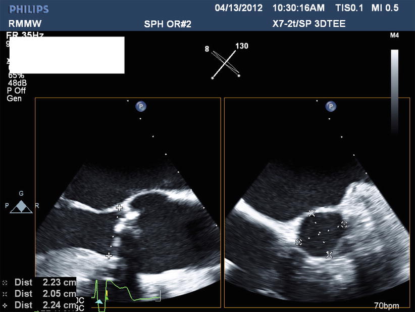

Fig. 28.5
X-plane transesophageal echocardiogram demonstrating two orthogonal views of the aortic valve and annulus
Annular measurements determine the size of prosthesis that will be implanted. Undersizing is associated with the risks of poor hemodynamics, PAR, valve migration, and embolism. Excessive oversizing can result in catastrophic consequences such as aortic rupture, tamponade, or aortic hematoma [1, 26]. TAVR device deployment relies on some degree of oversizing, as the valves depend on radial forces for secure seating. Approximately one in nine patients undergoing TAVR is left with moderate to severe PAR, which is associated with adverse outcomes [11, 57, 58]. The main causes of PAR after TAVR are valve undersizing and incorrect positioning [59–61]. CT-based sizing guidelines are in development to integrate 3D CT data into the valve selection process, which is currently based on echocardiographic measurements [14, 26].
There are no fundamental differences between TF- and TA-TAVR, with respect to annular sizing. The main differences in annular sizing relate mainly to the specific imaging modality employed. In general, annulus size as measured by TTE is 1 mm smaller than that measured by TEE. TEE size is generally 1–1.5 mm smaller than that measured by MDCT [41, 54]. As noted, good agreement has been reported between CMR and MDCT.
Summary
TAVR is currently reserved for patients with symptomatic severe AS, in whom surgery is either high risk or unfeasible. Many procedures have been performed to date, with acceptable outcomes. The application of multimodality imaging in patient selection and pre-procedural imaging promises to further refine these steps with the aim of reducing procedural complications and unsatisfactory patient outcomes.
Imaging for the patient selection process is common to both TF- and TA-TAVR approaches. For pre-procedural imaging, annular sizing is also common to both approaches, being used to identify the potential for procedural complications and to size the device. The main imaging differences between TF- and TA-TAVR relate to assessment of the aortoiliofemoral arterial system, and whether the proposed access route would be a suitable one. Size parameters, morphology, and concomitant structural features of the ventricle, root, aorta, and iliofemoral arteries determine suitability for TF- or TA-TAVR.
References
1.
2.
3.
4.
5.
6.
Himbert D, Descoutures F, Al-Attar N, et al. Results of transfemoral or transapical aortic valve implantation following a uniform assessment in high-risk patients with aortic stenosis. J Am Coll Cardiol. 2009;54:303–11.PubMedCrossRef
Stay updated, free articles. Join our Telegram channel

Full access? Get Clinical Tree


