Fig. 22.1
(a) The Canadian C-spine rule (Adapted with permission from Stiell et al. [27]). (b, c) Normal lines on lateral view of the cervical spine. (b) On the lateral radiograph of the cervical spine, the anterior spinal line (3), posterior spinal line (2), and spinolaminar line (1) are located along the anterior cortex of vertebral bodies, posterior cortex of vertebral bodies, and spinolaminar junctions, respectively. (c) Discontinuous anterior spinal line (3), posterior spinal line (2), and spinolaminar line (1) are seen on lateral radiograph of the cervical spine in a patient with type 2 dens fracture (arrowhead)
In case if cervical plain radiographs are obtained for trauma due to unavailability of emergent CT, an adequate cervical spine series must include five views: a true lateral view, which must include all seven cervical vertebrae and the cervicothoracic junction; an anteroposterior view; an open-mouth odontoid view; and both the oblique views. A swimmer’s view may be necessary to adequately show the lower cervical spine. Any film series that does not include these five views or which does not visualize all seven cervical vertebrae and the junction of C7–T1 is inadequate.
Flexion and extension views of the cervical spine are contraindicated in case of cervical spine fracture. They were used in the past for suspected ligamentous injuries; however, currently they have been replaced by MRI for suspected soft tissue trauma. In rare instances, they have been used for detecting new malalignment or exaggeration of the existing listhesis in patients with degenerative changes and in patients with equivocal MRI findings.
Cervical Spine Lines and Spaces
The cervical spine lines should be continuous curves through the bony elements regardless of the degree of flexion or extension, and any misalignment of these lines should be viewed as a sign of ligamentous injuries or occult fractures. The exception to this finding would be from anterior pseudosubluxation ligamentous laxity, which can occur at the C2–C3 level and less commonly at the C3–C4 level. Normal cervical spine lordosis can sometimes be reversed due to the presence of cervical collar, patient positioning, or muscle spasm.
There are four basic lines to evaluate alignment on lateral view of the cervical spine (Fig. 22.1b, c). These lines include anterior spinal line, posterior spinal line, spinolaminar line, and posterior spinous process line.
Predental Space or Atlanto-Dens Interval Space
The space between the odontoid process and the anterior portion of the ring of C1 should be less than 3.5 mm in adults and less than 5 mm in children. An increase in this space is presumptive evidence of a fracture of C1 or of the odontoid process, although it may also represent ligamentous injury at this level.
Prevertebral Space
Prevertebral soft tissue swelling (more than 6 mm at C2, more than 22 mm at C6) is highly specific for a fracture but not very sensitive. Soft tissue swelling in symptomatic patients should be considered an indication for further radiographic evaluation.
Interspinous and Intervertebral Distance
The spinous processes are examined to evaluate for abnormal widening or fanning of the spinous processes. If abnormal widening of the intervertebral or interspinous distance or angulation of more than 10° is present, a ligamentous injury or fracture should be considered.
Basion-axial interval (BAI) is the distance from the basion (inferior tip of the clivus) to a line drawn along the posterior body of C2, which should measure less than 12 mm.
Vertical basion-dens distance should measure less than 12 mm.
Indication for CT or MR Angiogram
Concomitant arterial injury although rare can occur with penetrating or blunt cervical spine injury causing intimal tears or rupture of the vasa vasorum leading to intramural hematoma, traumatic dissections, stenosis or occlusion, pseudoaneurysms, or rarely transection. CT or MR angiogram is noninvasive and should be obtained in patients with a high clinical suspicion, neurological deficits, if the cervical fracture is extending into the carotid canal or foramen tranversarium and in patients with severe trauma such as facet dislocation, vertebral subluxation, or multiple fractures. Vertebral arterial injury tends to be more common than carotid arterial injury due to close proximity to the spine. Imaging findings are depicted as intimal flaps, segmental or focal narrowing, or occlusions on CT or MR angiograms.
Indication for Spine MRI
In patients with severe fractures, neurological deficits, significant pain, or high clinical suspicion based on the mechanism of injury, MRI of the spine should be obtained to evaluate for ligamentous injuries, traumatic disk herniation, spinal cord edema, cord contusion or compression, spinal cord transection, or prevertebral, intramedullary, or epidural hematoma. The utility of obtaining MRI in obtunded patients with negative spine CT findings is still debatable; however, recent evidence suggests that if an adequate neurological exam cannot be carried out in the first 24 h, MRI of the spine should be obtained, especially in high-speed trauma where ligamentous or soft tissue injury of the cervical spine is a possibility. The following sequences are usually obtained in trauma MRI, sagittal and axial T1-weighted images, sagittal and axial T2-weighted images, and sagittal gradient sequence.
Classification of Cervical Spine Fractures
Cervical spine fractures are classified based on the mechanism of injury and only the commonly encountered fractures will be discussed further [11, 12] (Tables 22.1, 22.2, 22.3, and 22.4).
Table 22.1
Cervical injury by flexion mechanism
Mechanism | Submechanism | Fracture |
|---|---|---|
Flexion | Flexion-distraction and rotational forces | Unilateral or bilateral facet dislocation, anterior subluxation |
Hyperflexion and compression | Flexion teardrop fracture | |
Hyperflexion avulsion forces | Clay-shoveler’s fracture | |
Anterior compression | Wedge compression fracture |
Table 22.2
Cervical injury by extension mechanism
Mechanism | Submechanism | Fracture |
|---|---|---|
Extension | Hyperextension with distraction | Hangman’s fracture |
Hyperextension with axial loading | Hyperextension sprain and fracture-dislocation | |
Severe hyperextension | Lamina fracture | |
Rotation and impaction | Pillar fracture | |
Avulsion forces | Extension teardrop fracture | |
Hyperextension and compression | Posterior arch of C1 fracture |
Table 22.3
Cervical injury by axial loading
Mechanism | Submechanism | Fracture |
|---|---|---|
Axial load | Burst compression | Jefferson fracture, Jefferson variants, and lateral mass fractures |
Vertical axial compression | Burst fractures |
Table 22.4
Cervical injury by complex mechanism
Mechanism | Submechanism | Fracture |
|---|---|---|
Complex | Severe extension or flexion with distraction and posterior translation | Atlantooccipital dissociation |
Severe flexion-extension, distraction, and rotational forces | Atlantoaxial instability | |
Flexion or extension loading | Odontoid fracture |
Cervical Spine Fractures
Atlantooccipital Dissociation
Complete dislocation is fatal due to stretching injury of the brain stem. Subluxation is rare and can be missed on plain films. It should be suspected in patients with severe facial trauma, and the current methods used to determine subluxation are based on the distances between the occiput and axis which are as follows: Basion-axial interval (BAI) is the distance from the basion (inferior tip of the clivus) to a line drawn along the posterior body of C2, which should measure less than 12 mm. Vertical Basion-dens distance which should measure less than 12 mm (Fig. 22.2).
Fig. 22.2
Atlantooccipital dissociation. (a–c) Midline Sagittal CT reformation, parasagittal CT reformation, and 3D image shows widening to the atlantooccipital joint (arrowheads) and increased distance between the dens and the clivus
Occipital Condyle Fractures
These fractures are discussed with spine trauma due to the mechanism and their association with other cervical spine fractures. They occur from high-energy blunt trauma due to axial loading and lateral bending. Fractures of the occipital condyles are often undiagnosed on plain radiography and prevertebral soft tissue swelling may be the only radiographic marker (Fig. 22.3). These fractures may extend into the hypoglossal canal or the jugular foramen; therefore, clinical signs of injury to cranial nerves IX to XII may be found. Anderson-Montesano divides occipital condyle fractures into three types (Table 22.5):
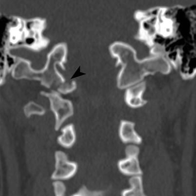
Fig. 22.3
Occipital condyle fracture. Coronal CT of the cervicothoracic junction shows minimal medially displaced oblique fracture (arrowhead) of the right occipital condyle
Table 22.5
Types of occipital condyle fractures
Types | Description |
|---|---|
1 | Comminuted impacted vertically oriented fracture without or with minimal displacement. Usually stable unless bilateral |
2 | More extensive skull base fracture extending into one or both the occipital condyles |
3 | Inferior medial avulsion fracture caused by a pull of the alar ligament with medial displacement of the fragment into the foramen magnum. Generally considered unstable since the contralateral alar ligament or tectorial ligament may be compromised and stressed resulting in partial or complete tear or if the degree of displacement is greater than 5 mm, if concomitant atlantooccipital dislocation is present, or if the fractures are bilateral |
Jefferson Fracture
This occurs with axial loading injury with downward compression forces to C1, through the occipital condyles which can cause Jefferson fracture, Jefferson variants, or lateral mass fractures. The classic Jefferson fracture is a four-part fracture of the anterior and posterior arches (Fig. 22.4a). Jefferson variants are two- and three-part fractures (Fig. 22.4b) with the most common one being fracture of one anterior and two posterior arches. On frontal radiography, the presence of Jefferson fracture is implied by offset of the lateral masses of C1 relative to C2 and widening of the atlantodental interval. On MDCT with reformats, the fracture is easy to identify. These fractures can be unstable, if they are associated with disruption of the transverse atlantal ligament which fixes the dens to the anterior arch of C1 or when the lateral mass cumulative displacement is greater than 7 mm, if the atlanto-dens interval is greater than 5 mm or when they are associated with C2 fractures. Neurological compromise is infrequent as the fractures cause widening of the C1, thereby limiting cord compression. If the axial loading force is eccentric, a lateral mass fracture may result. This fracture is often associated with fracture of the occipital condyle or articular process, and they are regarded as unstable fractures because the transverse atlantal ligament is often detached.
Fig. 22.4
Classic 4-part Jefferson fracture. (a) Classic 4-part Jefferson fracture. Axial CT shows four-part fracture (arrowheads) including bilateral fractures of the anterior arch of C1, minimally displaced fracture of the left posterior arch and nondisplaced fracture of the right posterior arch of C1. (b) 3-part Jefferson fracture variant. Axial CT shows three-part fracture (arrowheads) including displaced bilateral fractures of the anterior arch of C1 and nondisplaced fracture of the right posterior arch of C1
Dens Fracture
Anderson and D’Alonso classified dens fracture based on the location as types 1, 2, and 3 (Table 22.6). Type 1 fracture (Fig. 22.5a) is rare but stable. Type 2 (either acute or ununited) (Fig. 22.5b) and Type 3 fractures (Fig. 22.6) are considered unstable because they can result in atlantoaxial instability (since the ligaments, proximal fragment, C1, and occiput act as a single unit during motion).
Table 22.6
Types of dens fracture
Types | Description |
|---|---|
1 | Rare oblique fracture involving the superolateral aspect of the dens from avulsion of the alar ligaments and are usually stable injuries |
2 | Most frequent unstable transverse fracture involving the base of the dens |
3 | Unstable fracture involving the base of the dens extending into the lateral masses and body of the axis. It has a better prognosis for healing because of the larger surface involved |
Fig. 22.5
Dens fracture. (a) Type 1 dens fracture. Coronal CT shows transverse fracture (arrowhead) through the tip of the dens. (b) Type 2 dens fracture. Sagittal CT shows oblique fracture (arrowhead) through the base of the dens, with mild anterior displacement and angulation of the superior dens
Fig. 22.6
Type 3 dens fracture. (a) Sagittal CT shows comminuted fracture (arrowhead) of the dens extending into the body with mild retropulsion of the superior dens into the spinal canal. Marked prevertebral soft tissue swelling is also noted. (b) Coronal CT shows the fracture (arrowhead) extending into the vertebral body and lateral mass of C2. (c) Sagittal MPGR MRI demonstrates fracture through the dens (arrowhead) with posterior displacement of the superior dens, spinal stenosis, cord edema (curved arrow), contusion, and hemorrhage
Anomalies of Dens
The os terminale is an ossification center at the tip of the dens, which normally fuses by 12 years of age but may remain unfused in adulthood and simulate a type 1 fracture. The os odontoideum formation is debatable as some authors think it is congenital due to lack of fusion with the base of the dens or posttraumatic fracture of the synchondrosis before closure at age 5–6 years resulting in a large ossicle that is separated from the hypoplastic dens by a wide gap. It may be fixed to the arch of C1 or the clivus and may simulate a nonunited dens fracture or rarely result in atlantoaxial instability [8].
Hangman’s Fracture
Bilateral pars interarticularis fracture at C2 is known as hangman’s fracture and usually also involves the bilateral neural arches and the pedicles causing traumatic spondylolysis or spondylolisthesis (Fig. 22.7). They have been classified by Effindi and modified by Levine as follows (Table 22.7):
Fig. 22.7


Hangman’s fracture. (a) Axial CT shows minimally displaced fracture (arrowheads) extending through the bilateral pars interarticularis of C2. (b, c) Parasagittal CT shows vertical fracture (arrowhead) through the C2 pars interarticularis
Related posts:
Stay updated, free articles. Join our Telegram channel
Full access? Get Clinical Tree
