Key Facts
- •
Total joint replacement is a highly successful method for providing pain relief from various arthritic conditions.
- •
Radiographs remain the standard technique for evaluating the position and integrity of joint replacements.
- •
Joint aspiration is critical for identifying infection following joint replacement but is not infallible.
- •
Technical modifications have permitted computed tomography and magnetic resonance imaging to become important methods for the assessment of prosthetic complications such as granuloma formation.
- •
Combined white blood cell and marrow imaging (indium 111 WBC/technetium 99m sulfur colloid) is the standard imaging examination for identifying infected joint prostheses.
TOTAL HIP REPLACEMENT
Joint replacement surgery is one of the great success stories of modern medicine. Results of total hip replacement are excellent, producing marked improvement in physical function, social interaction, and overall health. Modern prostheses are expected to last more than 15 years. The foundation for this success was the introduction by Sir John Charnley of the cemented metal to polyethylene prosthesis in the early 1960s. Currently, over 600,000 hip replacements are performed in Europe each year. A total of 202,500 primary total hip arthroplasties were performed in the United States in 2003, and it is estimated that by 2030, the demand for these operations will grow by 174% to 572,000.
Indications
Joint replacement is generally considered for patients 65 years of age or older. Candidates for total hip replacement usually have arthritis with disabling hip pain and functional limitation in spite of adequate medical therapy ( Table 30-1 ). Patients 65 years of age or older suffering pain that interferes with sleep or activities and is unresponsive to 3 to 6 months of conservative treatment (such as anti-inflammatory medication) may be candidates for joint replacement. In patients aged 55 to 65, a longer course of conservative treatment is usually warranted before joint replacement is considered. Recent investigations seek to further improve these prostheses and techniques to allow use of prostheses in younger individuals who may have greater physical demands and the desire for early return to work. Some areas of investigation, include optimizing implant positioning, decreasing wear, preserving bone and minimally invasive surgery.
| Indications | Unremitting pain |
| Contraindications/relative contraindications | Active infection |
| Vascular insufficiency | |
| Paralysis | |
| Severe obesity | |
| Prior surgical joint fusion |
Types of Prostheses
Initial hip prostheses consisted of a metallic femoral component and a high density polyethylene acetabular component ( Figure 30-1 ). Contemporary prostheses are modular including a separate femoral head and sometimes a separate femoral neck or proximal body, thus allowing adjustments to provide optimal biomechanics. The acetabular liner is inserted with a metal backing that provides the irregular surface for bone ingrowth. These metal-backed bone ingrowth acetabular components have shown lower rates of radiographic loosening at 10 years compared with cemented acetabular components.

Preserving Bone: Surface Replacements
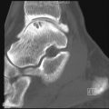
Surface replacements have shorter femoral component stems allowing less bone to be resected and are, therefore, important options for younger patients. The current generation of surface replacements has a metal-to-metal articulation (not metal to high density polyethylene as older surface replacements) ( Figure 30-2 ). As summarized by Eingartner, problems may include adverse reactions to metal ion release (from wear), reduced acetabular options if revision surgery is necessary, a more invasive initial surgical procedure, and the danger of femoral neck fracture. Indications for surface replacement may include active younger patients (males < 65, women < 60) with good bone quality ( Table 30-2 ).

| Indications | Young active patients (women < 60, men < 65) with good bone stock |
| Contraindications | Metal allergy |
| Renal insufficiency | |
| Dysplasia | |
| Osteonecrosis | |
| Femoral neck deformity |
Proper patient selection (including radiologic evaluation of the proximal femur for bone density, shape, biomechanics and focal bone defects) and attention to operative details are important for achieving optimal results of surface replacement. Shmalzried et al. noted a suboptimal femoral shape for surface replacement to be characterized by a broad, short, femoral neck with a femoral head neck diameter ratio of less than 1.2 cm or neck length less than 2 cm. Poor biomechanics included limb length discrepancy greater than 1 cm or neck-shaft angle less than 120 degrees. Low bone density would increase the risk of postoperative femoral neck fracture and cysts larger than 1 cm in diameter are poor prognostic factors.
The cause of most surface replacement failures is femoral component loosening. Femoral neck fractures may complicate surface replacement procedures and can be minimized by attention to technical details including avoiding notching of the lateral femoral neck. Postoperative radiographs should, therefore, be scrutinized for metaphyseal radiolucencies, femoral neck notching, change in component position, and femoral fractures.
Fixation of Components
Methyl methacrylate cement was used by Charnley to provide stress transmission from the components to bone. “Bone ingrowth” fixation was later developed in which an irregular prosthetic surface allows bone to grow between the surface irregularities (pores) to provide fixation that was both durable and adaptable to changes in stress ( Figure 30-3 ). For this to occur, certain geometric properties of the surface pores are necessary and there must be relatively little motion between the implant and the bone during healing. The term “osseointegration” is sometimes used to describe bone ingrowth fixation. Osseointegration refers to the stable anchorage of an implant achieved by direct bone-to-implant contact; since fibrous tissue may be present around bone ingrowth components this designation may or may not be entirely accurate.


Coating the bone ingrowth surfaces with hydroxyapatite was developed to provide initial stability to allow bone ingrowth without the presence of a fibrous tissue interface (osseointegration). This coating is not visible on radiographs.
Hybrid fixation describes the situation in which a cemented femoral component is paired with a bone ingrowth acetabular component ( Figure 30-3, B ). Acetabular component stability is improved with bone ingrowth fixation as compared to cement fixation. Hybrid fixation is used most often in patients over the age of 65. Two bone ingrowth femoral stem designs are currently used most often, components with a straight stem and extensive surface coating for bone ingrowth and components with a tapered stem and proximal coating. Loosening rates for both types of components used in the last decade are extremely low.
In bipolar prostheses , the acetabular component is not fixed to the acetabulum ( Figure 30-3, C ). Theoretically (but not always actually), motion can occur between the femoral component and the acetabulum and between the acetabular component and the native acetabulum.
Articular Surfaces (Decreasing Wear)
Highly cross-linked polyethylene is the most common liner surface for total hip replacements today. This liner results in decreased wear when compared to conventional polyethylene components and possibly a decrease in osteolysis. A 10-fold decrease in mean liner wear per year has been noted (0.20 for conventional polyethylene liners versus 0.02 mm/year). Particle size is also different compared to conventional polyethylene components.
Ceramic-on-ceramic bearings have been developed ( Figure 30-4 ). Intermediate-term data have shown a low rate of femoral osteolysis. Fracture of the femoral head or chipping of the acetabular liner and audible squeaking have been reported, however.

Decreasing wear of articular surfaces is an important factor in increasing prosthetic life and reducing complications.
Metal-on-metal bearings also have the potential advantage of decreasing wear. However, as noted by Huo, controversy continues regarding the safety of metal-on-metal bearing surfaces, particularly with regard to release of metal ions and the potential for hypersensitivity reactions. Delayed hypersensitivity reactions may be the cause of early osteolysis in some patients with these prostheses.
Minimally Invasive Surgery
The term “minimally invasive surgery” may refer the use of a traditional surgical approach but with minimal skin and soft tissue incision (minimal incision technique), or it may refer to a technique using two incisions. Minimally invasive techniques attempt to shorten the hospital stay and postoperative recovery time by decreasing the extent of soft tissue disruption (usually including a smaller skin incision). Although more rapid improvement in function has been noted after 3 months, no advantage to these techniques is documented. Overall, the cost of the two incision technique and the standard technique are not significantly different. Complication rates appear greater with the two-incision technique, but tend to decrease with experience.
Imaging of Total Hip Replacement
Preoperative Assessment
Preoperative imaging is essential for determining the degree of cartilage and bone damage and for preoperative planning. Generally, at the Brigham and Women’s Hospital, an anteroposterior radiograph of the pelvis and anteroposterior and “frog lateral” views of the affected hip that includes at least the proximal third of the femur are obtained for these assessments. A magnification marker placed alongside the hip at the level of the bone allows for correction of radiographic magnification and for any enlargement or minification of digital images. A pelvic baseline such as the biischial line facilitates evaluation of leg-length discrepancy ( Figure 30-5 ). The position of the native acetabulum can be determined (using the Ranawat triangle method). Areas of bone deficiency should be looked for and can be filled using grafts or specialized components. Computed tomography (CT) can be used to evaluate bone stock in questionable cases. Wide femoral canals, as assessed by a calcar-to-canal isthmus ratio, may not be suitable for bone ingrowth femoral components. As noted above, the shape and angulation of the femoral head and neck, the degree of cyst formation and leg-length disparity are considerations in selecting patients for surface replacement.

Postoperative Radiographs
Timing
An initial postoperative radiograph is indicated in all patients, and must include the bone past the tip of the femoral stem since this area is prone to fracture. As indicated in the American College of Radiology appropriateness criteria, the schedule for obtaining radiographs in asymptomatic individuals thereafter is uncertain. Lifelong follow-up is recommended, however, even in asymptomatic patients since osteolysis may occur without symptoms.
Initial radiographs and serial radiographs may be critical for detecting complications, including infection, wear, and osteolysis. Stulberg et al. proposed CT scanning to help determine the extent and location of silent osteolysis and to guide medical and surgical treatment. An initial CT scan is advocated 7 to 10 years postoperatively to establish a baseline; additional CT scans should be done on the basis of the appearance of the original scan. The decision to operate on a patient with extensive acetabular osteolysis is based on the likelihood that a well-fixed cup may become loose during the patient’s lifetime.
Reporting
A standard system of reporting the radiographic results after total hip replacement has been proposed. Positioning of components is assessed as shown in Table 30-3 and Figure 30-6 . When describing the periprosthetic regions of a total hip arthroplasty, the nomenclature of DeLee and Charnley is used for the acetabulum (zones I to III) and that of Gruen et al. is used for the proximal femur (regions 1 to 7) ( Figure 30-7 ).
| Usual Appearance | Abnormal Appearances | |
|---|---|---|
| Acetabular component position | Inclination angle usually 45 degrees; (range 35 to 55 degrees) | |
| Acetabular polyethylene liner | Femoral head is normally centered within acetabulum | Thinning of distance from femoral head to lateral acetabulum suggests wear or liner disruption |
| Acetabular screws | Do not project more than slightly into pelvis | Rarely, protruding screws may be associated with vascular or visceral injury. CT suggested if suspected. |
| Acetabular fixation | < 2-mm lucency around acetabular cement Remodeling around bone ingrowth component | 2 mm or more cement–bone interface, change in position of component indicate loosening. |
| Femoral component position | Stem tip usually centrally located or directed medially (valgus) | Varus position is not optimal |
| Femoral fixation | Cement: Close apposition/interdigitation of cement and bone. Bone ingrowth: interdigitation of bone with the prosthetic bone ingrowth surface, “spot welds,” stress shielding. Stable 1-mm lucency may indicate fibrous ingrowth. | Cement: 2 mm or more of lucency especially if along entire cement mantle, cement fracture, change in component position indicate loosening. Development of metal–cement lucency laterally. Bone ingrowth: 2 mm or more of lucency along bone ingrowth surface, progressive shedding of surface beads, settling after 1 year or > 1 cm indicate loosening. |
| Adjacent bone | Stress shielding—Bone resorption occurs in unstressed areas (e.g., medial femoral cortex) after bone ingrowth stabilizes component. Stress shielding does not progress after 1–2 years | Fracture: Marked sclerosis at tip of prosthesis may indicate loosening. Focal lucent lesions (granulomas) |
| Soft tissues | Gas resorbs shortly postoperatively | Heterotopic bone may be visible within weeks |


Fixation
Cemented Components
Methyl methacrylate cement is made radiopaque so that its distribution and interdigitation with trabeculae can be evaluated on radiographs. Optimally, cement should fill the space between the femoral component and the proximal medial cortex and extend past the tip of the femoral stem by about 2 cm ( Figure 30-8 ). Thin (1 to 2 mm) lucencies may develop along the cement bone interface owing to the presence of fibrous tissue.

Uncemented Components
Bone ingrowth fixation attempts to allow bone to grow into the irregular surface (pores) of the components to provide a lasting bond between them. Fibrous tissue ingrowth also occurs to some extent and may provide stability but is not ideal. When bone ingrowth occurs, stress from weight bearing is transmitted through the relatively rigid prosthesis resulting in decreased stress on some areas of bone (such as the proximal medial femur). This process is called stress shielding, and the decrease in bone density that results indicates bone ingrowth has occurred. The bone loss usually stops at 1 or 2 years after surgery, and increasing bone loss after that time is worrisome for other processes (such as granuloma formation).
Acetabular Component
Moore et al. compared radiographic appearances of bone ingrowth acetabular components with findings at revision surgery and found five signs useful in determining stable fixation ( Figure 30-9 ):
- •
Absence of radiolucent lines
- •
Presence of a superolateral buttress
- •
Medial bone stress-shielding
- •
Radial trabeculae
- •
Inferomedial buttress

Ninety-seven percent of the cups with three or more of these signs were stable at the time of revision surgery whereas 83% of the cups with two or fewer signs were loose ( Table 30-4 ).
| Location | Finding |
|---|---|
| Femoral component | No lucent lines |
| Stress shielding | |
| Thin proximal lucent line along bone ingrowth surface especially laterally (usually 1-2 mm) with a thin adjacent sclerotic line | |
| Endosteal sclerosis (“spot weld”) | |
| Focal cortical thickening (may also be abnormal) | |
| Periosteal reaction due to stress changes | |
| Settling of stem of < 1 cm occurring < 1 year after surgery | |
| Acetabular component | No lucent lines |
| Superolateral, inferomedial buttressing | |
| Medial stress shielding | |
| Radial trabeculae |
Femoral Component
Radiographs are useful in documenting femoral component fixation. Three appearances have been described for assessing fixation of bone ingrowth stems. Although described for extensively coated components these findings are usually applied to proximally coated components as well.
In stable fixation by bone ingrowth, bone extends to and between the prosthetic surface beads. Areas of increased endosteal bone density (“spot welds”) develop usually at the junction of the smooth and bone ingrowth surfaces. The cortices proximally become less dense due to stress shielding. No sclerotic lines (“demarcation lines”) are present along the bone ingrowth portion of the stem (although they may be seen along the smooth portion of the stem). These findings are visible by 1 year after surgery ( Figure 30-10 ).


In stable fixation by fibrous tissue, thin sclerotic lines develop along the bone ingrowth area but no change in component position occurs. Kaplan et al. 21 noted this finding in 79% of cases, usually within the first year after surgery.
Unstable fixation, or widening of a lucent zone along the bone ingrowth surface shows. Continued displacement of surface beads suggests loosening. Settling of bone ingrowth components may occur early in the course but settling greater than 1 cm, especially if it continues more than 1 year after surgery, has a strong association with implant failure.
Lucent lines may develop along the nonbone ingrowth (smooth) surface of a femoral component due to the differences in stiffness between the bone and the prosthesis. This may occur even with well-fixed components. Screws may be inserted to fix the acetabular component while bone ingrowth is occurring. Acetabular screw penetration into the pelvis should be noted. Oblique radiographs may be helpful in delineating this. Screws that are perpendicular to the acetabular surface in the posterior quadrants usually are safe while those fixed perpendicular in the anterior quadrants are generally thought unsafe. If there is any question about screw position and its relation to vital structures, CT is performed.
Arthrography
Intra-articular contrast injection is usually performed as an adjunct to joint aspiration to allow the intra-articular needle position to be confirmed. Normally, injected arthrographic contrast fills a small smooth joint capsule and fills little, if any, of the cement bone interface.
Contrast injection into the joint is recommended as a good practice to confirm needle position and define any abnormality of the joint (e.g., fistulae, bursae, or synovitis) whenever aspiration is performed.
Anesthetic Arthrography
The injection of anesthetic into the joint may be helpful in clarifying the origin of hip pain. Pain relief suggests an intra-articular source whereas absence of relief is considered nonspecific.
Anesthetic injection into the hip joint may help determine the source of hip pain. Pain relief suggests an intra-articular source whereas absence of relief is considered nonspecific.
Scintigraphy
Increased radionuclide uptake may be seen on bone scans “normally” following total hip arthroplasty, but gradually decreases over a period of 6 to 12 months.
Computed Tomography
While CT scanning is traditionally limited by the presence of metal hardware, newer multichannel scanners and attention to technical parameters have made this technique of considerable value for assessing prosthetic complications ( Figure 30-11 ). Reformatted images reconstructed from the original axial data set provide images in the sagittal and coronal planes analogous to standard radiographic projections.


Improvements in CT have made this an important technique for evaluating prostheses.
Technical factors for imaging of hip prostheses differ from standard body imaging techniques. Those suggested by Buckwalter et al. are shown in Table 30-5 . The radiation dose of these CT scans can be relatively high, and this should be considered when selecting imaging studies for younger individuals.
| Parameter | Recommended Value |
|---|---|
| Pitch a | Low (0.3 if possible) |
| kVp | 140 |
| mAs | 35-450 if one THR |
| 450-600 if bilateral THRs | |
| Focal spot | Small if possible |
| Dose modulation | Off |
| Detector array | Small |
| Scanned area | Tops iliac crests to tip of femoral stem (and cement if present) |
| Reconstruction algorithm | Standard or soft tissue |
| FOV | Both sides included |
| Spacing | 3-mm contiguous |
| Reconstructions | |
| Axial of hip | 160-220-mm FOV, mid-pelvis down |
| 1-1.5 mm thick, 50% overlap | |
| Soft image reconstruction filter | |
| Sagittal and coronal reformations (two sets) | Femoral stem, acetabulum, proximal femoral component |
| 1.5 mm thick | |
| Use hip images for source |
Normally, CT confirms the metallic femoral head to be centered in the acetabular liner (see Figure 30-11 ). Ceramic components are of homogeneous density (less dense than metal) and the interface between the acetabular and femoral components should be nearly imperceptible. Bone should be closely apposed to the cement. Any lucent lines along the cement should be thin. Stable uncemented acetabular components should normally confirm trabecular bone adjacent to the irregular bone ingrowth surfaces of the prosthesis.
CT is very useful in evaluating screw position, acetabular position in the sagittal plane (see Figure 30-11, C ) and granuloma formation. CT is extremely helpful in identifying and quantifying areas of osteolysis. Radiographs underestimate the degree and size of osteolytic bone destruction. Evaluation of surgically produced lytic lesions in a cadaver model with a hip replacement in place showed the sensitivity for detecting lesions was 51.7% for radiographs, 74.7% for CT, and 95.4% for MRI (using specific protocols for CT and MRI to decrease meal artifact).
Magnetic Resonance Imaging
Despite the fact that metal is a basic part of most total joint replacements and that metal induces artifacts on MRI, MRI can be used effectively in patients after total joint replacement especially if certain technical modifications are used.
Improved techniques have made MRI a useful modality for assessing joint prostheses. MRI is particularly helpful to assess patients with unexplained pain after joint replacement or to further assess abnormalities identified on other imaging studies.
Naraghi and White have reviewed the problems and the methods of improving MRI in patients with joint replacement. As they explain, a homogeneous magnetic field and gradients are required for MR imaging.
Metallic components become magnetized to some degree when placed in a magnetic field (magnetic susceptibility); this results in inhomogeneities in the local field, producing artifacts. This magnetization and, therefore, the artifact, is less in low magnetic fields and with certain metals such as titanium. Metal-induced artifacts include intra-voxel dephasing, misregistration, diffusion-related signal loss, and slice thickness variation. The artifacts related to the presence of metallic components can be minimized using various techniques, depending on the type of artifact ( Table 30-6 ). The tissues around the acetabular components are generally less well demonstrated than those around the femoral component.
| Artifact | Artifact Reduction Modification |
|---|---|
| Intravoxel dephasing | Use SE and FSE in lieu of GRE |
| Misregistration | Broaden receiver bandwidth |
| Use higher-frequency encoding strength | |
| Orient long axis of implant with B 0 (main magnetic field) | |
| Orient frequency encoding along long axis of implant | |
| Use lower magnetic field strength | |
| View angle tilting | |
| Diffusion-related signal loss | Use FSE and short TE sequences |
| Reduce interecho spacing | |
| Slice thickness variation | Reduce slice thickness |
| Increase matrix size | |
| Use 3D technologies | |
| Nonhomogeneous fat saturation | Use STIR instead of spectral fat saturation |
| Use modified three-point Dixon technique |
Complications of Total Hip Replacement
Loosening
Component loosening may be secondary to infection or to a reaction to particulate debris, usually small polyethylene liner wear particles. Late aseptic loosening is the most common reason for implant failure. Features of loosening that can be seen on radiographs are shown in Table 30-7 . Stumpe et al. diagnosed loosening (without infection) when at least one of the following criteria was present: migration (of less than 2 mm within 6 to 12 months), periprosthetic lucency (in a smooth [linear] fashion) 2 mm or greater in diameter, periosteal reaction (of the solid type), and/or cement fracture.
Late loosening of hip prostheses, often due to osteolysis from wear particles, is the most frequent reason for failure of total hip prostheses.
Differentiation of septic from aseptic loosening is difficult or impossible on radiographs. Absence of the sclerotic line (demarcation line) that is usually seen separating a lucent zone from the adjacent bone may be an indication of infection. In addition, rapid progression on serial radiographs is suggestive of infection.
Differentiation of septic from aseptic loosening is difficult or impossible on radiographs.
Currently, arthrography is not often used at our hospital for the diagnosis of component loosening (although it is often used as an adjunct to joint aspiration). CT or scintigraphy is more likely to be performed. For the most accurate detection of loosening on arthrography, high injection pressure and subtraction techniques are most helpful. Using these techniques, Maus et al. found a sensitivity of 96%, and specificity of 92% for the diagnosis of femoral loosening and a sensitivity of 97% and specificity of 68% for acetabular loosening. Arthrography indicates loosening following cemented total hip replacement if contrast at the cement bone interface extends past the intertrochanteric line of the femur for standard components or halfway down the stem for long-stemmed components. Acetabular component loosening is more likely if the contrast fills the entire cement bone interface, is in zones I and II or II and III, or if the contrast is thicker than 2 mm in any region.
The value of arthrography for the detection of loosening of bone ingrowth components is less clear than for cemented components as contrast may insinuate along portions of the prosthetic interface even if bone ingrowth is present in other areas.
Scintigraphy is useful for detecting loosening of total hip replacements. Generally focal areas of increased uptake after 1 year are thought to indicate loosening while diffuse uptake suggests infection; unfortunately, the patterns are not specific and patients with focal uptake may also have infection ( Figure 30-12 ).

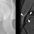
On MRI, loosening has been demonstrated as a nonenhancing linear area of low T1 signal and high T2 signal paralleling the femoral component ( Figure 30-13 ).

Wear and Osteolysis
Periprosthetic osteolysis is the major long-term complication of total hip arthroplasty. Harris notes it also to be “the major cause of acetabular component loosening, necessitating revision of acetabular components, a major contributor to loosening of femoral components, and the single most important process behind pathologic fractures of the femur and pathologic fractures of the acetabulum following total hip arthroplasty.” It is most often the result of a reaction to particles generated by wear of the ultra-high molecular-weight polyethylene acetabular liner. Development of alternative articulating surfaces (metal on metal, ceramic on ceramic and highly cross-linked polyethylenes) have decreased the prevalence of osteolysis and could eliminate it.
Measuring Wear
As noted above, the major cause of component failure is particle disease due most often to polyethylene wear and the subsequent development of periprosthetic osteolysis. Thinning of the acetabular liner due to wear can be evaluated on radiographs since it eventually leads to a visible asymmetry in the position of the metallic femoral head within the acetabular component. Usually the femoral head shifts superolaterally in the acetabulum as wear increases ( Figure 30-14 ). Several methods have been developed to quantify the amount of wear from radiographs. In 1973, Charnley and Cupic reported wear at 9 to 10 years by evaluating a single radiograph. Comparison of measurements on initial and follow-up radiographs is thought to be more accurate than a single measurement.

These methods assess wear in the superior and lateral dimension, termed “linear” wear, and this has been shown to correlate with osteolysis. Study of 235 Charnley low friction arthroplasties by Sochart followed 74 to 364 months showed that total wear averaged 2.1 mm (range, 0 to 7.2 mm), and the average wear rate was 0.11 mm per year, with the wear rate of revised components being twice that of surviving ones. For every additional millimeter of wear, the risk of acetabular revision in any 1 year increased by 45% and for the femur increased by 32%. Measurement of wear in the anteroposterior dimension from lateral radiographs can also be done providing a three-dimensional (3D) assessment.
Digital imaging and computer-aided analysis provides greater accuracy and reproducibility. Using weight-bearing radiographs to assess wear (rather than standard supine radiographs), has shown that measured vertical wear is significantly greater when radiographs are taken weight-bearing. Also, calculations of rates of linear wear of the acetabular component were significantly underestimated when radiographs were taken supine.
Wear of the acetabular liner leads to an asymmetrical position of the femoral head.
Evaluating Osteolysis
Osteolysis occurs and progresses without clinical symptoms, making detection by imaging essential. Unfortunately, radiographs are insensitive for the detection of osteolytic lesions generally, including those resulting from focal granulomatous lesions ( Figure 30-15 ).


A study of cadavers with bilateral total hip replacements and surgically created bone defects has confirmed radiography to be limited in its ability to detect areas of pelvic osteolysis (sensitivity 51.7%). Lesions of the posterior rim and ischium are most difficult to identify. Both MRI (using a specific protocol) and CT scanning with metal reduction techniques had better sensitivity (74.7% for CT and 95.4% for MRI) than radiography. Sensitivity improved with larger lesions; MRI was best for detecting small (< 3 cm) periacetabular lesions. Most of the underestimation of osteolytic lesions is in the detection of smaller lesions that may not be of clinical relevance. A strong correlation has been noted between the two-dimensional size and the 3D volume estimate of the lesions.
When evaluating radiographs or CT scans for areas of osteolysis, several points are helpful. Comparison with preoperative radiographs is useful to be sure that lucent areas seen postoperatively are not remnants of preoperative cysts. Lytic lesions should be described as to location and approximate size. Buckwalter notes that small cyst-like lucent lesions may be present normally at unoccupied screw holes possibly due to synovial fluid under pressure entering these areas although areas of osteolysis usually demonstrate a communication to the joint space. Cyst-like areas due to particle disease may extend into the soft tissues.
Foreign body granulomatous reaction with hyperplastic capsules can produce positive 18-F-fluorodeoxyglucose (FDG) positron emission tomography (PET) scans that can mimic infection.
Granulomas may mimic infection on PET scanning.
MRI is more sensitive for the detection of osteolysis than is radiography or CT. Osteolysis has been characterized on MRI as a localized periprosthetic intraosseous mass that is low in signal on T1-weighted images and low to intermediate in signal on T2-weighted images with a heterogeneous appearance. Peripheral and patchy internal enhancement is noted after intravenous contrast. A hypointense margin surrounds these lesions. Synovitis due to particle disease may also be seen before other imaging techniques demonstrate abnormalities.
Osteolytic defects and wear with stable components are treated with liner replacement and bone grafting. Follow-up CT examinations have shown a decrease in lesion size, confirming the efficacy of this treatment.
Fracture
Intraoperative fractures most often occur during broaching of the femoral canal. Periprosthetic fractures later are uncommon complications but are more frequent after revision than primary total hip replacement. These fractures are typically difficult to treat.
Dislocation
Dislocation continues to be a cause of early revision. Ali Khan et al. reviewed 6774 total hip replacements from multiple centers and found dislocation occurred in 2.1%. Component malposition such as an acetabular component that is too vertical or too anteverted or a femoral component that is too anteverted is often present. Other predisposing factors include the surgical approach and the presence of neurologic disorders.
Radiographs are usually diagnostic. Blocks to reduction may be identified. Also, complications following reduction (including incomplete reduction, fracture, dissociation of components) are occasionally seen ( Figure 30-16 ).


Infection
Two-thirds of periprosthetic hip infections develop during the first year after surgery. The diagnosis of postoperative infection can be difficult on clinical and on imaging evaluation, yet the results are critical since treatment differs if infection is found.
Aspiration for Joint Infection
Joint aspiration is the most important examination if infection of a joint replacement is suspected in spite of the fact that both false-positive and false-negative results are reported (sensitivity 50% to 93% and specificity of 82% to 97%). Levitsky et al. noted cultures to be superior to three-phase bone scan or sedimentation rate to detect infection in total hip replacements. A prospective study of 202 patients prior to revision surgery, however, showed that no patient with infection had both negative C-reactive protein (CRP) and sedimentation rate. A more recent series of 220 patients (235 hip arthropathies) confirmed that no hip was infected if the erythrocyte sedimentation rate was < 30 mm/hr and the C-reactive protein was < 10 mg/dL. In one series, aspiration of the joint (excluding patients on antibiotics) yielded 0.86 sensitivity, 0.94 specificity, 0.67 positive predictive value (PPV), and 0.98 negative predictive value (NPV). In addition to culturing joint fluid, contrast injected at arthrography may show irregular collections extending from an infected joint (that may need separate aspiration) or demonstrate fistulae ( Figure 30-17 ).