Key Facts
- •
Intraarticular contrast injection under image guidance can be combined with radiography to evaluate intraarticular structures or with computed tomography (CT) or magnetic resonance imaging (MRI) to provide detailed assessment of both intraarticular and extraarticular structures.
- •
Magnetic resonance arthrography involves injection of a dilute gadolinium solution into the joint, but iodinated contrast is usually also injected to confirm intraarticular needle position.
- •
CT arthrography is performed using iodinated contrast and/or air to outline articular structures.
- •
These procedures are generally safe; uncommon complications include infection and bleeding.
- •
Injection under image guidance, usually fluoroscopy, is of benefit in deeper joints (e.g., the hip, sacroiliac joints), in the midfoot and subtalar joints, and in larger patients.
Arthrography is the intraarticular injection of contrast usually under image guidance to improve the visualization of intraarticular structures (e.g., ligaments, cartilaginous surfaces, free bodies). The type of contrast that is delivered into the joint will vary depending upon the patient’s presenting symptoms and the subsequent imaging modality chosen. Other applications of contrast injection into a joint include confirmation of intraarticular needle placement at the time of joint aspiration or prior to intraarticular delivery of medications. When performed with proper technique, under image guidance, arthrography is relatively safe with few contraindications.
For many years arthrography was performed using fluoroscopic guidance to monitor contrast injection and provide postinjection radiographs for evaluation of intraarticular structures. This procedure coated the articular structures and filled the joint, providing limited evaluation of the joint capsule, articular cartilage, menisci, intraarticular bodies, and immediate surrounding structures. With advances in imaging technology, arthrography is now often performed followed by magnetic resonance (MR arthrography) or computed tomography (CT arthrography) for a complete evaluation of the joint and the surrounding structures. Imaging with either magnetic resonance imaging (MRI) or CT following arthrography improves both the sensitivity and specificity of these individual imaging modalities for evaluation of the intrinsic structures of a joint. By distending the joint capsule with contrast, the intrinsic redundancy is reduced, allowing specific structures to be assessed that would normally not be as well seen on the standard MR or CT examinations. This is especially true when evaluating the shoulder or hip for labral abnormalities, the wrist for ligamentous injury, and the elbow for intraarticular bodies. These techniques can be applied to virtually any joint; additional indications are discussed below.
It is important to specify the type of examination (MR or CT) required because this will determine the type of contrast that will be instilled into the joint. MR arthrography allows for multiplanar imaging of an articulation with no radiation exposure (except that incurred during fluoroscopy for contrast instillation). MR arthrography usually requires the intraarticular administration of a mixture of gadolinium, saline, and non-ionic iodinated contrast. This combination allows visualization of the contrast both at fluoroscopy and at MRI. Optimal technique must be followed when performing MR arthrography to prevent the intraarticular injection of air bubbles, which may result in artifacts that could simulate intraarticular bodies. Because of the broad capabilities of MRI and the intraarticular contrast, MR arthrography has the advantage of being able to evaluate not only the intraarticular structures but also the adjacent soft tissues and extraarticular structures including the adjacent osseous marrow. MR arthrography cannot be performed in patients who have contraindications to MRI and may be limited in those who have surgical metal in the area (e.g., fracture fixation hardware), which may affect the visualization of adjacent structures. MRI examinations are contraindicated in those patients with various surgical implants such as pacemakers, defibrillators, and spinal electronic stimulators. Occasionally, an MR arthrogram my fail due to equipment problems, a claustrophobic or uncooperative patient, or an unusually large patient. In these cases, a CT arthrogram is a good alternative examination.
CT arthrography usually requires the intraarticular administration of non-ionic iodinated contrast material to distend the joint and coat articular structures. Current multidetector CT technology allows for submillimeter-thick slices to examine the joint with high spatial resolution. Through the use of multiplanar reconstructions (MPRs), many of the imaging planes traditionally utilized on MR examinations (axial, sagittal, and coronal) can be duplicated on CT examination for excellent visual evaluation of the articulation. The most important indications for this technique over MR arthrography include a failed MR arthrogram, an obese or severely claustrophobic patient, a patient with an MR-incompatible implanted medical device, or a postoperative patient with metal hardware in close proximity to the joint ( Box 5-1 ). In addition, in locations without access to an MR scanner, CT arthrography can serve as a reasonable alternative imaging modality. The limitations of CT arthrography include exposure to ionizing radiation, the necessity for intraarticular administration of iodinated contrast, and the more limited soft tissue contrast when compared with MRI, potentially compromising evaluation of structures adjacent to the joint (e.g., the bursal side of the rotator cuff).
Failed or contraindicated MRI examination
Claustrophobic patient
Obese patient
Metallic hardware near the joint
MRI scanner not available
If proper technique is followed and image guidance is utilized, there are few contraindications to either CT or MR arthrography ( Box 5-2 ). One contraindication occurs when the superficial tissues overlying the joint are infected, because entering the joint through these infected tissues could introduce bacteria into the articulation. If a safe alternative approach to the joint cannot be identified, then the exam should not be performed.
Joint aspiration/arthrography should not be performed through an area of infected soft tissue.
Infected or damaged soft tissue over the injection site
Anticoagulation (INR > 2) *
* Higher levels have been shown in the literature to be safe.
Prior allergic reaction to contrast or anesthetic (another contrast can sometimes be substituted)
Inability to lie flat or remain still
Other skin abnormalities such as psoriatic involvement should also be avoided. Patients with anticoagulation or elevated clotting times should be aware of the risks associated with this procedure, and consultation should be made with the ordering physician to discuss alternatives or medical management of the anticoagulation prior to proceeding with the examination. Although Thumboo et al. indicate that joint aspiration is safe if the international normalized ratio (INR) is less than 4.5, it is the practice at our institution to perform these procedures only with an INR of 2 or less.
There are numerous relative contraindications. The most significant of these to consider when performing MR or CT arthrography is an allergy to iodinated contrast. Even though there is only a small amount of iodinated contrast administered during MR arthrography (to confirm needle position), the possible risk for a serious reaction is still present. These patients can be premedicated with corticosteroids and diphenhydramine according to the American College of Radiology guidelines prior to the initiation of the examination. *
* See http://www.acr.org/Secondary/MainMenuCategories/quality_safety/contrast_ manuel. aspx .
More often, however, if iodinated contrast cannot be used to confirm correct intraarticular needle placement, needle position can be confirmed by test injection of normal saline when the needle seems to be in correct position. If reaspiration indicates that the needle is not in a vessel and the saline advances without resistance, the needle can be assumed to be positioned in the joint and the gadolinium contrast can then be instilled. Aspiration of joint fluid prior to injection is reassuring but has been shown to be an imperfect indicator that subsequent injection will be intraarticular. In patients with absolute contraindications to gadolinium and iodinated contrast, air can be injected into the joint followed by CT. Claustrophobia is also a relative contraindication for the performance of MR arthrography, and in these cases either a mild sedative can be administered to the patient or a CT arthrogram can be performed.As with any invasive procedure, it is important to consider the benefits for the patient compared with the potential risks involved from the examination. The utilization of iodinated contrast material for either MR or CT arthrography carries a small risk of a reaction in all patients. Initially, for the first few hours following injection, slight joint discomfort may be present, but this will usually resolve as the instilled contrast is reabsorbed. Vasovagal reactions are rare and are usually managed in the fluoroscopy suite. The most serious (and fortunately rare) risk associated with arthrography is the development of a joint infection. This risk can be minimized through adherence to a strict aseptic protocol. There are no reports of serious adverse events such as anaphylactic shock or other events requiring treatment in the intensive care unit or hospitalization as a result of intraarticular gadolinium for MR arthrography.
Contrast reaction and the introduction of infection are rare but potentially serious complications of arthrography.
SHOULDER ARTHROGRAPHY
Ultrasound and noncontrast MRI examinations are the primary modalities currently utilized to evaluate shoulder problems, especially rotator cuff tears. These methods have largely supplanted “conventional” arthrography in which radiographs are obtained following intraarticular contrast administration. Arthrography in conjunction with MRI or CT is used most often to evaluate the intraarticular structures (e.g., glenoid labrum, synovial disorders) that are not as easily seen without intraarticular contrast. Other applications of shoulder arthrography include the treatment of adhesive capsulitis, as well as the intraarticular delivery of corticosteroids.
Arthrography Technique
The intraarticular injection of contrast is usually performed under fluoroscopic guidance. The patient is then transferred to either the CT or MRI scanner for the completion of the imaging portion of the procedure. Ideally, the patient should be imaged within the 30 minutes following contrast injection; therefore coordination in the scheduling of fluoroscopy and MRI or CT is important.
Placement of the needle within the joint must avoid contrast injection into the cartilage, labrum, or capsular attachments to be of maximal diagnostic benefit. Many injection techniques have been described; the anterior approach is the most commonly utilized. For injection using the anterior approach, the patient in placed in the supine position with the humerus in external rotation. External rotation results in exposure of more of the articular surface of the humeral head anteriorly and also increases the intraarticular area for needle insertion. The area of desired needle placement (either on the medial, superior third of the humeral head [the rotator cuff interval], or the inferior third of the humeral head) is visualized under fluoroscopy and marked on the patient’s skin ( Figure 5-1 ). This area is then prepared and draped in a sterile fashion. The subcutaneous tissues are anesthetized. A 22-gauge (G), 3.5-cm spinal needle is advanced in an anteroposterior direction until it contacts the humeral head. Once the needle tip contacts the cortex of the humeral head, confirmation of intraarticular needle position is made by injecting contrast, which should immediately flow away from the needle tip if it is within the joint. Ten to 15 mL (usually about 14 mL) of contrast is then injected until the patient feels full or injection becomes more difficult. Injections of less than 15 mL will decrease the likelihood of extraarticular leakage, which could lead to failure to diagnose a full-thickness rotator cuff tear. Overdistension may lead to capsular rupture and contrast extravasation, which could limit joint distension.

The type of contrast utilized will depend on the imaging that the patient will have following the procedure. If the patient is having a CT exam, a non-ionic iodinated agent will be utilized. If MRI is to follow, a dilute solution of gadopentetate dimeglumine mixed with a small amount of iodinated contrast will be injected (10 mL saline, 0.1 mL gadopentetate, and 10 mL non-ionic iodinated contrast). Following the injection, the patient will be moved through a full range of motion to coat the articular structures. Various fluoroscopic images are usually obtained before the patient is taken for the MRI or CT portion of the examination.
Indications
Many factors are considered when deciding which patients should undergo arthrography as part of their evaluation. Instability of the shoulder is a common clinical problem, especially in young active individuals. The glenoid labrum, the glenohumeral ligaments, and the muscles of the rotator cuff all contribute to stability. The diagnosis of abnormality of these structures, especially the labrum, on a nonarthrographic study may be difficult because of the redundancy of the axillary recess and the presence of clefts and overlying structures that may mimic abnormalities. By distending the capsule with contrast, these structures can be more fully evaluated ( Figure 5-2 ). The use of MR or CT arthrography allows for better detection of capsulolabral abnormalities and partial thickness rotator cuff tears ( Figure 5-3 ). Distension of the joint capsule allows differentiation between irregular tears of the labrum and normal anatomic variants such as the sublabral sulcus and foramen ( Figure 5-4 ). The glenohumeral ligaments are routinely visualized on MR or CT arthrography exams owing to the joint distension. Abnormalities of these ligaments can more easily be identified on MR or CT arthrography than on noncontrast studies ( Figure 5-5 ) ( Table 5-1 ).


| Imaging Technique | Uses |
|---|---|
| MR arthrography | Athletes with chronic injuries |
| Instability (patient < 40 years old) | |
| Rotator cuff tears | |
| Biceps anchor evaluation | |
| Labral evaluation | |
| Identification of intraarticular loose bodies | |
| Postoperative evaluation of the labrum or rotator cuff | |
| CT arthrography | Postoperative rotator cuff evaluation |
| Any of the above indications if contraindications exist for MRI |
Findings
The normal shoulder joint capsule is smooth; irregularity or filling defects suggest synovitis. Normally the biceps tendon sheath and axillary recess fill with contrast. A small joint volume and nonfilling of these structures can be seen in adhesive capsulitis.
Adhesive capsulitis can be apparent on arthrography if the joint capacity is unusually small with absent filling of the biceps sheath and axillary recess and high injection pressure.
Articular-sided rotator cuff tears will show contrast extending from the joint into the substance of the rotator cuff (partial tear) or through the entire thickness of the cuff into the subacromial subdeltoid bursa (full thickness, complete tears). Sometimes complete tears can allow contrast to communicate with the acromioclavicular (AC) joint (termed the geyser sign ) ( Figure 5-6 ). Not only can the tear be recognized, but the size of the tear, quality of the torn edges, and any atrophy or fatty replacement of the muscles can be assessed. These are important surgical considerations.
Some full-thickness rotator cuff tears are accompanied by chronic fluid extravasation into the AC joint. This produces a fluid mass on clinical examination that corresponds to the contrast extravasation seen on arthrography, termed the geyser sign .

Labral tears can be identified by abnormalities in the shape of the labrum or contrast extravasation into labral tissue. Sometimes additional maneuvers, such as having the patient imaged while in external rotation and abduction (the ABER position), can be helpful for labral assessment. These supplemental images may be added to the protocol at the MRI facility where the study is planned, depending on the clinical indications for examination.
MRI examination protocols are tailored to the specific clinical question.
HIP ARTHROGRAPHY
The initial imaging for the evaluation of hip pain should be radiographs to exclude etiologies such as fractures and avascular necrosis (AVN). Noncontrast MRI is effective in the evaluation of hip pain with normal radiographs, showing acute fractures as well as confirming cases of AVN that are not visible or are atypical on radiographic examination. Unless a large joint effusion is present, evaluation of the intrinsic structures of the hip joint (e.g., the labrum) is limited on MRI due to redundancy within the capsule. MR and CT arthrography are effective in the evaluation of these structures including the labrum, ligaments, and articular cartilage.
Technique
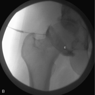
When performing hip arthrography, the patient should be lying supine on the fluoroscopy table with the hip to be injected in neutral position. External rotation of the femur should be avoided because this moves the femoral vessels and nerves laterally, potentially in the path of the needle. A small pillow may be placed under the knee to not only make the patient more comfortable but also to relax the anterior joint capsule. Multiple injection approaches have been described. Initially, the femoral artery is palpated and marked to avoid injury during the needle placement. The overlying tissues are then prepared with alcohol and Betadine and draped in a sterile fashion. The skin and subcutaneous tissues are anesthetized. A common approach involves advancing a 22 G spinal needle under fluoroscopic guidance to the lateral aspect of the superolateral femoral head-neck junction until the cartilage is reached ( Figure 5-7 ). A different technique involves advancing the needle straight down to the femoral neck at the midpoint between the base of the femoral head and the intertrochanteric line. The latter approach has been shown to produce less patient discomfort but does have a higher rate of extravasation of contrast from the joint capsule. After placing the needle within the joint, the joint should be aspirated, especially if administering gadolinium contrast to prevent its dilution. Joint fluid is sent for culture and crystals depending on the clinical circumstance. In all techniques, a small amount of non-ionic iodinated contrast material should be injected to confirm location of the needle within the joint capsule. Then between 8 and 20 mL of contrast should be injected into the joint for good distension. The administration of 0.3 mL of 1:1000 epinephrine into the hip joint can also be performed to slow the absorption of the contrast agent to allow clarity of images if there is an imaging delay. Fluoroscopic images will be obtained throughout the procedure to confirm needle placement and immediately after injection of the contrast into the joint to document intraarticular injection and delineate gross joint anatomy. Following this, the patient will be transferred to the MRI or CT suite via wheelchair for the completion of the examination.

Indications
Hip pain has numerous etiologies including both intrinsic abnormalities and pain referred from remote sites. When encountered in the young patient or athlete, concern for the intrinsic structures should be the primary consideration. The use of conventional radiographs is not reliable in identifying all abnormalities, but radiographs should be obtained prior to other imaging tests. As in the shoulder, the joint capsule of the hip has intrinsic redundancy that limits evaluation of the internal structures. In the absence of preexisting joint fluid, the evaluation of the acetabular labral complex is difficult on conventional MR and CT examinations. Distension of the joint capsule following the addition of contrast into the joint allows for easier evaluation of the intrinsic structures ( Figures 5-8 and 5-9 ). In addition, intraarticular bodies and the articular cartilage can be evaluated ( Figure 5-10 ). Patients with a history of acetabular dysplasia can be routinely evaluated utilizing MR or CT arthrography to monitor the progression of osteoarthritis and to determine when surgical treatment should be considered ( Table 5-2 ). Detailed imaging of the joint may be difficult with MR arthrography in those patients who are large or obese; in these situations, CT arthrography should be considered as an alternative imaging modality.


Related posts:

Stay updated, free articles. Join our Telegram channel

Full access? Get Clinical Tree


