Imaging Techniques in Orthopedics
Choice of Imaging Modality
In this chapter, the principles and limitations of current imaging techniques are described. Understanding the basis of the imaging modalities available to diagnose many commonly encountered disorders of the bones and joints is of utmost importance. It may help determine the most effective radiologic technique, minimizing the cost of examination and the exposure of patients to radiation. To this end, it is important to choose the modality appropriate for specific types of orthopedic abnormalities and, when using conventional techniques (namely, “plain” radiography), to be familiar with the views and the techniques that best demonstrate the abnormality. It is important to reemphasize that conventional radiography remains the most effective means of demonstrating bone and joint abnormalities.
The use of radiologic techniques differs in evaluating the presence, type, and extent of various bone, joint, and soft-tissue abnormalities. Therefore, the radiologist and the orthopedic surgeon must know the indications for use of each technique, the limitations of a particular modality, and the appropriate imaging approaches for abnormalities at specific sites. The question, “What modality should I use for this particular problem?” is frequently asked by radiologists and orthopedic surgeons alike, and although numerous algorithms are available to evaluate various problems at different anatomic sites, the answer cannot always be clearly stated. The choice of techniques for imaging bone and soft-tissue abnormalities is dictated not only by clinical presentation but also by equipment availability, expertise, and cost. Restrictions may also be imposed by the needs of individual patients. For example, allergy to ionic or nonionic iodinated contrast agents may preclude the use of arthrography; the presence of a pacemaker would preclude the use of magnetic resonance imaging (MRI); physiologic states, such as pregnancy, preclude the use of ionized radiation, favoring, for instance, the use of ultrasound (US). Time and cost consideration should discourage redundant studies.
No matter what ancillary technique is used, conventional radiograph should be available for comparison. Most of the time, the choice of imaging technique is dictated by the type of suspected abnormality. For instance, if osteonecrosis is suspected after obtaining conventional radiographs, the next examination should be MRI, which detects necrotic changes in bone long before radiographs, computed tomography (CT), or scintigraphy becomes positive. In the evaluation of internal derangement of the knee, conventional radiographs should be obtained first and, if the abnormality is not obvious, should again be followed up by MRI, because this modality provides exquisite contrast resolution of the bone marrow, articular cartilage, ligaments, menisci, and soft tissues. MRI and magnetic resonance arthrography (MRa) are currently the most effective procedures for the evaluation of rotator cuff abnormalities, particularly when a partial or complete tear is suspected. Although ultrasonography can also detect a rotator cuff tear, its low sensitivity (68%) and low specificity (75% to 84%) make it a less definitive diagnostic procedure. In evaluating a painful wrist, conventional radiographs should precede the use of more advanced techniques, such as CT-arthrography or MRI. If a tear of triangular fibrocartilage complex, a tear of intercarpal ligaments, or a carpal tunnel syndrome is suspected, MRI is preferred because it provides a high-contrast difference among muscles, tendons, ligaments, and nerves. Similarly, if osteonecrosis of carpal bones is suspected and the conventional radiographs are normal, MRI would be the method of choice to demonstrate this abnormality. In the evaluation of fractures and fracture healing of carpal bones, CT is the procedure of choice, preferred over MRI, because of the high degree of spatial resolution. In diagnosing bone tumors, conventional radiography is still the gold standard for diagnostic purposes. However, to evaluate the intraosseous and soft-tissue extension of tumor, it should be followed by either CT scan or MRI, with the latter modality being more accurate. To evaluate the results of radiotherapy and chemotherapy of malignant tumors, dynamic MRI using gadopentetate dimeglumine (gadolinium-DTPA—Gd-DTPA) as a contrast enhancement is far superior to scintigraphy, CT, or even “plain” MRI.
Imaging Techniques
Conventional Radiography
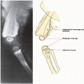
The most frequently used modality for the evaluation of bone and joint disorders, and particularly traumatic conditions, is conventional radiography. The radiologist should obtain at least two views of the bone involved, at 90-degree angles to each other, with each view including two adjacent joints (see Fig. 4.1). This decreases the risk of missing an associated fracture, subluxation, and/or dislocation at a site remote from the apparent primary injury. In children, it is frequently necessary to obtain a radiograph of the normal unaffected limb for comparison. Usually, the standard radiography comprises the anteroposterior and lateral views; occasionally, oblique and special views are necessary, particularly in evaluating complex structures, such as the elbow, wrist, ankle, and pelvis. A weight-bearing view may be of value for a dynamic evaluation of the joint space under the weight of the body (see Fig. 13.16). Special projections, such as those described in the following chapters,
may, at times, be required to demonstrate an abnormality of the bone or joint to further advantage.
may, at times, be required to demonstrate an abnormality of the bone or joint to further advantage.
Magnification Radiography
Magnification radiography is occasionally used to enhance bony details not well appreciated on the standard radiographic projections and to maximize the diagnostic information obtainable from a radiographic image. This technique involves a small focal-spot radiographic tube, a special screen-film system, and increased object-to-film distance, resulting in a geometric enlargement that yields magnified images of the bones and joints with greater sharpness and greater bony detail. This technique is particularly effective in demonstrating early changes in some arthritides (see Fig. 12.7) as well as in various metabolic disorders (see Fig. 26.9B). Occasionally, it may be useful in demonstrating subtle fracture lines otherwise not seen on routine projections.
Stress Views
Stress views are important in evaluating ligamentous tears and joint stability. In the hand, abduction-stress film of the thumb may be obtained when a gamekeeper’s thumb, resulting from a disruption of the ulnar collateral ligament of the first metacarpophalangeal joint, is suspected (see Fig. 7.103B). In the lower extremity, stress views of the knee and ankle joints are occasionally obtained. The evaluation of knee instability caused by ligament injuries may require the use of this technique in cases of a suspected tear of the medial collateral ligament and, less frequently, in evaluating an insufficiency of the anterior and posterior cruciate ligaments. The evaluation of ankle ligaments also may require stress radiography. Inversion (adduction) and anterior-draw stress films are the most frequently obtained stress views (see Figs. 4.4, 10.10, and 10.11).
Scanogram
The scanogram is the most widely used method for limb-length measurement. This technique requires a slit-beam diaphragm with a 1/16-in. opening attached to the radiographic tube and a long film cassette. The radiographic tube moves in the long axis of the radiographic table. During an exposure, the tube traverses the whole length of the film, scanning the entire extremity. This technique allows the x-ray beam to intersect the bone ends perpendicularly; therefore, comparative limb lengths can be measured. When a motorized radiographic tube is not available, a modified technique may be used with three separate exposures over the hip joints, knees, and ankles. In this technique, an opaque tape measure is placed longitudinally down the center of the radiographic table. Occasionally, an orthoroentgenogram is obtained. For this technique, the patient is positioned supine with the lower limbs on a 3-ft-long cassette and a long ruler at one side. A single exposure is made, centered at the knees to include the entire length of both limbs and the ruler.
Fluoroscopy and Videotaping
Fluoroscopy is a fundamental diagnostic tool for many radiologic procedures, including arthrography, tenography, bursography, arteriography, and percutaneous bone or soft-tissue biopsy. Fluoroscopy combined with videotaping is useful in evaluating the kinematics of joints. Because of the high dose of radiation, however, it is only occasionally used, such as in evaluating the movement of various joints or to detect transient subluxation (i.e., carpal instability) (see Fig. 7.85). Occasionally, it is used after fractures in follow-up examinations of the healing process to evaluate the solidity of the bony union. Fluoroscopy is still used in conjunction with myelography, where it is important to observe the movement of the contrast column in the subarachnoid space; in arthrography, to check the proper placement of the needle and to monitor the flow of the contrast agent; and intraoperatively, to assess the reduction of a fracture or placement of hardware.
Digital Radiography
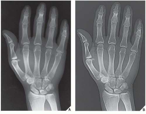
Digital (computed) radiography (DR) is the name given to the process of digital image acquisition using an x-ray detector comprising a photostimulable phosphor imaging plate and an image reader-writer that processes the latent image information for subsequent brightness scaling and laser printing on film (Fig. 2.1). The system works on the principle of photostimulated luminescence. When the screen absorbs x-rays, the x-ray energy is converted to light energy by the process of fluorescence, with the intensity of light being proportional to the energy absorbed by the phosphor. The stimulated light is used to create a digital image (a computed radiograph).
A major advantage of computed radiography over conventional film/screen radiography is that once acquired, the digital image data are readily manipulated to produce alternative renderings. Potential advantages of digitization include contrast and brightness optimization by the manipulation of window width and level settings, as well as a variety of imageprocessing capabilities, quantitation of image information, and facilitation of examination storage and retrieval. In addition, energy subtraction imaging (also called dual-energy subtraction) may be acquired. Two images, acquired either sequentially or simultaneously with different filtration, are used to reconstruct a soft-tissue-only image or a bone-only image.
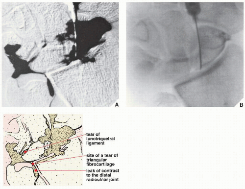
In digital subtraction radiography, a video processor and a digital disk are added to a fluoroscopy imaging complex to provide online viewing of subtraction images. This technique is most widely used in the evaluation of the vascular system, but it may also be used in conjunction with arthrography to evaluate various joints. The use of high-performance video cameras with low-noise characteristics allows single video frames of precontrast and postcontrast images to be used for subtraction. Spatial resolution can be maximized using a combination of geometric magnification, electric magnification, and a small anode-target distance. The subtraction technique removes surrounding anatomic structures and thus isolates the opacified vessel or joint, making it more conspicuous.
Nonvascular DR may be used to evaluate various bone abnormalities and, in conjunction with contrast injection, a procedure called digital subtraction arthrography (Fig. 2.2); to evaluate subtle abnormalities of the joints, such as tears of the triangular fibrocartilage or intercarpal ligaments in the wrist; or to evaluate the stability of prosthesis replacement. DR offers the potential advantages of improved image quality, contrast sensitivity, and exposure latitude, and it provides efficient storage, retrieval, and transmission of radiographic image data. Digital images may be displayed on the film or on a video monitor. A significant advantage of image digitization is the ability to produce data with low noise and a wide dynamic range suitable for window-level analysis in a manner comparable to that used in a CT scanner.
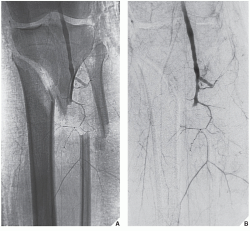
Digital subtraction angiography (DSA), the most frequently used variant of DR, can be used in the evaluation of trauma, bone and soft-tissue tumors, and in general evaluation of the vascular system. In trauma to the extremity, DSA is effectively used to evaluate arterial occlusion, pseudoaneurysms, arteriovenous fistulas, and transection of the arteries (Fig. 2.3). Some advantages of DSA over conventional film techniques are that its images can be studied rapidly and multiple repeated projections can be obtained. Bone subtraction is useful in clearly delineating the vascular structures. In the evaluation of bone and soft-tissue tumors, DSA is an effective tool for mapping tumor vascularity.
Tomography
Tomography is a body-section radiography that permits more accurate visualization of lesions too small to be noted on conventional radiographs or demonstrates anatomic detail obscured by overlying structures. It uses continuous motion of the radiographic tube and film cassette in opposite directions throughout the exposure, with the fulcrum of the motion located in the plane of interest. By blurring structures above and below the area being examined, the object to be studied is sharply outlined on a single plane of focus. The focal plane may vary in thickness according to the distance the x-ray tube travels; the longer the distance (or arc) traveled by the tube, the thinner the section in focus. Newly developed tomographic units can localize the image more precisely and have aided greatly in the ability to detect lesions as small as approximately 1 mm.
The simplest tomographic movement is linear, with the radiographic tube and film cassette moving on a straight line in opposite directions. This linear movement has little application in the study of bones because it creates streaks that often interfere with radiologic interpretations. Resolution of the plane of focus is much clearer when there is more uniform blurring of undesired structures. This requires a multidirectional movement, such as in zonography or in circular
tomography, in which the radiographic tube makes one circular motion at a preset angle of inclination. More complex multidirectional hypocycloidal or trispiral movements increase the distance of excursion of the tube and create a varying angle of projection of the x-ray beam during the exposure. These complex movements are more advantageous because they produce even greater blurring and yield the sharpest images. Trispiral tomography used to be an important radiographic technique in the diagnosis and management of a variety of bone and joint problems (see Figs. 7.48 and 7.54B). Currently it has been, however, almost completely replaced by CT.
tomography, in which the radiographic tube makes one circular motion at a preset angle of inclination. More complex multidirectional hypocycloidal or trispiral movements increase the distance of excursion of the tube and create a varying angle of projection of the x-ray beam during the exposure. These complex movements are more advantageous because they produce even greater blurring and yield the sharpest images. Trispiral tomography used to be an important radiographic technique in the diagnosis and management of a variety of bone and joint problems (see Figs. 7.48 and 7.54B). Currently it has been, however, almost completely replaced by CT.
Computed Tomography
CT is a radiologic modality containing an x-ray source, detectors, and a computer data-processing system. The essential components of a CT system include a circular scanning gantry, which houses the x-ray tube and image sensors, a table for the patient, an x-ray generator, and a computerized data-processing unit. The patient lies on the table and is placed inside the gantry. The x-ray tube is rotated 360 degrees around the patient while the computer collects the data and formulates an axial image, or “slice.” Each cross-sectional slice represents a thickness between 0.1 and 1.5 cm of body tissue.
The newest CT scanners use a rotating fan of x-ray beams, a fixed ring of detectors, and predetector collimator. A highly collimated x-ray beam is transmitted through the area being imaged. The tissues absorb the x-ray beam to various degrees depending on the atomic number and density of the specific tissue. The remaining, unabsorbed (unattenuated) beam passes through the tissues and is detected and processed by the computer. The CT computer software converts the x-ray beam attenuations of the tissue into a CT number (Hounsfield units) by comparing it with the attenuation of water. The attenuation of water is designated as 0 (zero) H, the attenuation of air is designated as -1,000 H, and the attenuation of normal cortical bone is +1,000 H. Routinely, axial sections are obtained; however, computer reconstruction (reformation) in multiple planes may be obtained if desired.
The introduction of spiral (helical) scanning was a further improvement of CT. This technique, referred to as volume-acquisition CT, has made possible a data-gathering system using a continuous rotation of the x-ray source and the detectors. It allows the rapid acquisition of volumes of CT data and renders the ability to reformat the images at any predetermined intervals ranging from 0.5 to 10.0 mm. Unlike standard CT, in which up to a maximum of 12 scans could be obtained per minute, helical CT acquires all data in 24 or 32 seconds, generating up to 92 sections. This technology has markedly reduced scan times and has eliminated interscan delay, and hence interscan motion. It also has decreased the motion artifacts, improved the definition of scanned structures, and markedly facilitated the ability to obtain three-dimensional (3D) reconstructions generated from multiple overlapping transaxial images acquired in a single breath hold. Spiral CT allows data to be acquired during the phase of maximum contrast enhancement, thus optimizing the detection of a lesion. The data volume may be viewed either as conventional transaxial images or as multiplanar and 3D reformations.
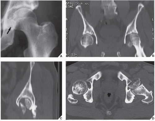
CT is indispensable in the evaluation of many traumatic conditions and various bone and soft-tissue tumors because of its cross-sectional imaging capability. In trauma, CT is extremely useful to define the presence and extent of a fracture or dislocation; to evaluate various intraarticular abnormalities, such as damage to the articular cartilage or the presence of noncalcified and calcified osteocartilaginous bodies; and to evaluate adjacent soft tissues. CT is of particular importance in the detection of small bony fragments displaced into the joints after trauma, in the detection of small displaced fragments of the fractured vertebral body, and in the assessment of a concomitant injury to the cord or thecal sac. The advantage of CT over conventional radiography is its ability to provide excellent contrast resolution, accurately measure the tissue attenuation coefficient, and obtain direct transaxial images (Fig. 2.4; see also Figs. 11.24C, 11.35B, and 11.61B). A further
advantage is its ability—through data obtained from thin, contiguous sections—to image the bone in the coronal, sagittal, and oblique planes using reformation technique. This multiplanar reconstruction is particularly helpful in evaluating the vertebral alignment (Fig. 2.5), demonstrating horizontally oriented fractures of the vertebral body; in evaluating complex fractures of the pelvis, hip (Fig. 2.6), and knee (Fig. 2.7); or in evaluating calcaneus abnormalities, of the sacrum and sacroiliac joints, sternum and sternoclavicular joints, temporomandibular joints, and wrist. Modern CT scanners use collimated fan beams directed only at the tissue layer undergoing investigation. The newest advances in sophisticated software enable 3D reconstruction, which is helpful in analyzing regions with complex anatomy, such as the face, pelvis,
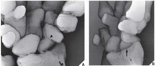
vertebral column, foot, ankle, and wrist (Figs. 2.8,2.9,2.10,2.11). New computer systems now permit the creation of plastic models of the area of interest based on 3D images. These models facilitate operative planning and allow rehearsal surgery of complex reconstructive procedures.
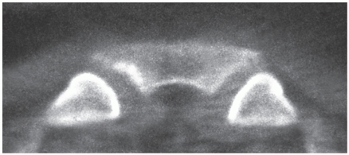 FIGURE 2.4 CT transaxial imaging. In this direct transaxial image, the sternoclavicular joints are well depicted. |
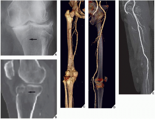
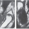
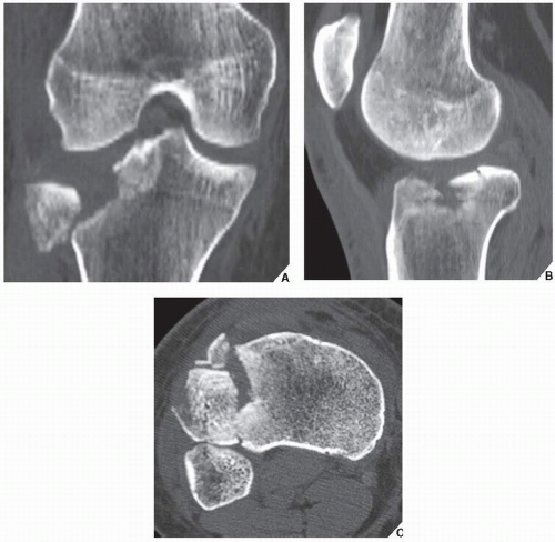 FIGURE 2.7 CT multiplanar imaging. Coronal (A), sagittal (B), and axial (C) CT images of the knee show the details of a complex fracture of the lateral tibial plateau. |
Most recently, with the advent of 64-channel multidetector row CT (MDCT), images can be generated with subsecond gantry rotation times yielding high-resolution volume data sets, and at the same time minimizing the radiation dose to the patient. Even more advanced is high-resolution flat-panel volume CT (fpVCT), which uses digital flat-panel detectors and provides volumetric coverage as well as ultra-high spatial resolution in two-dimensional (2D) and 3D projections. Furthermore, it reduces metal and beam hardening artifacts. In addition to the above-listed features, fpVCT also allows dynamic imaging of time-varying processes.
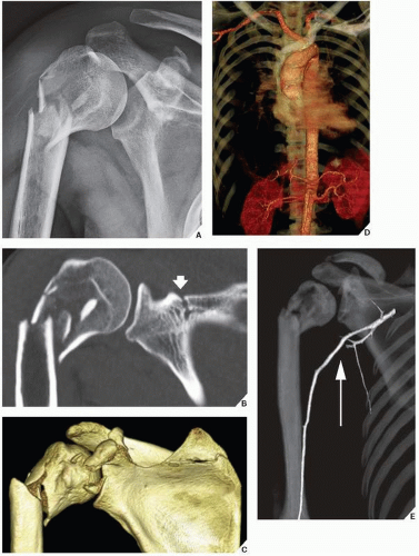
In the evaluation of traumatic abnormalities, 3D CT-angiography is effectively used to determine the presence or absence of injury to the vessels near the fractured bones (Figs. 2.12 and 2.13).
CT plays a significant role in the evaluation of bone and soft-tissue tumors because of its superior contrast resolution and its ability to
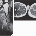
measure the tissue attenuation coefficient accurately. Although CT, by itself, is rarely helpful in making a specific diagnosis, it can precisely evaluate the extent of the bone lesion and may demonstrate a break through the cortex and the involvement of surrounding soft tissues. Moreover, CT is very helpful in delineating a tumor in bones having complex anatomic structures, such as the scapula, pelvis, and sacrum, which may be difficult to image fully with conventional radiographic techniques. CT examination is crucial to determine the extent and spread of a tumor in the bone if limb salvage is contemplated, so that a safe margin of resection can be planned (Fig. 2.14). It can effectively demonstrate the intraosseous extension of a tumor and its extraosseous involvement of soft tissues such as muscles and neurovascular bundles. It is also useful for monitoring the results of treatment, evaluating for the recurrence of a resected tumor, and demonstrating the effect of nonsurgical treatment such as radiation therapy and chemotherapy.
measure the tissue attenuation coefficient accurately. Although CT, by itself, is rarely helpful in making a specific diagnosis, it can precisely evaluate the extent of the bone lesion and may demonstrate a break through the cortex and the involvement of surrounding soft tissues. Moreover, CT is very helpful in delineating a tumor in bones having complex anatomic structures, such as the scapula, pelvis, and sacrum, which may be difficult to image fully with conventional radiographic techniques. CT examination is crucial to determine the extent and spread of a tumor in the bone if limb salvage is contemplated, so that a safe margin of resection can be planned (Fig. 2.14). It can effectively demonstrate the intraosseous extension of a tumor and its extraosseous involvement of soft tissues such as muscles and neurovascular bundles. It is also useful for monitoring the results of treatment, evaluating for the recurrence of a resected tumor, and demonstrating the effect of nonsurgical treatment such as radiation therapy and chemotherapy.
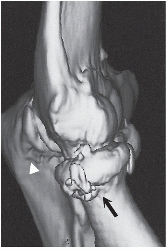 FIGURE 2.9 CT 3D imaging. 3D CT reformation of the elbow shows a fracture of the neck of the radius (arrow) and a fracture of the olecranon process (arrowhead). |
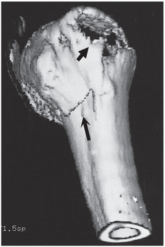 FIGURE 2.10 CT 3D imaging. A fracture of the surgical neck of the humerus (long arrow) and a displaced fracture of the greater tubercle (short arrow) are well demonstrated. |
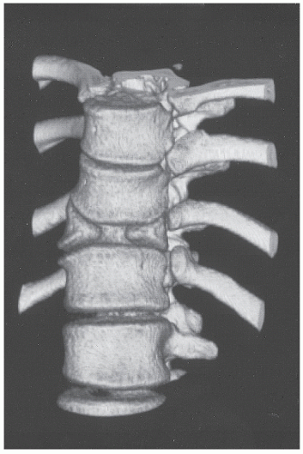 FIGURE 2.11 CT 3D imaging. 3D CT reformation of the thoracic spine shows sagittal cleft with an anterior defect of T11, a typical appearance of congenital butterfly vertebra. |
Occasionally, iodinated contrast agents may be used intravenously to enhance the CT images. A contrast agent directly alters image contrast by increasing the x-ray attenuation, thus displaying increased brightness in the CT images. It can aid in identifying a suspected soft-tissue mass when initial CT results are unremarkable, or it can assess the vascularity of the soft-tissue or bone tumor.
CT has a crucial role in bone mineral analysis. The ability of CT to measure the attenuation coefficients of each pixel provides a basis for accurate quantitative bone mineral analysis in cancellous and cortical bones. Quantitative CT (QCT) is a method for measuring the lumbar spine mineral content in which the average density values of a region of interest are referenced to that of calibration material scanned at the same time as the patient. Measurements are performed on a CT scanner using a mineral standard for simultaneous calibration and a computed radiograph (scout view) for localization (see Fig. 26.12). The evaluation of bone mass measurement provides valuable insight into improving the evaluation and treatment of osteoporosis and other metabolic bone disorders.
CT is also a very important modality for successful aspiration or biopsy of bone or soft-tissue lesions, because it provides visible guidance for precise placement of the instrument within the lesion (Fig. 2.15).
Some disadvantages of CT include the so-called average volume effect, which results from a lack of homogeneity in the composition of the small volume of tissue. In particular, the measurement of Hounsfield units results in average values for the different components of the tissue. This partial volume effect becomes particularly important when normal
and pathologic processes interface within a section under investigation. The other disadvantage of CT is poor tissue characterization. Despite the ability of CT to discriminate among some differences in density, a simple analysis of attenuation values does not permit precise histologic characterization. Moreover, any movement of the patient will produce artifacts that degrade the image quality. Similarly, an area that contains metal (e.g., prosthesis or various rods and screws) will produce significant artifacts, although recently several different acquisition and reconstruction parameters have been developed to significantly reduce artifacts related to the metallic implants. Finally, the radiation dose may occasionally be high, particularly when contiguous and overlapping sections are obtained during examination.
and pathologic processes interface within a section under investigation. The other disadvantage of CT is poor tissue characterization. Despite the ability of CT to discriminate among some differences in density, a simple analysis of attenuation values does not permit precise histologic characterization. Moreover, any movement of the patient will produce artifacts that degrade the image quality. Similarly, an area that contains metal (e.g., prosthesis or various rods and screws) will produce significant artifacts, although recently several different acquisition and reconstruction parameters have been developed to significantly reduce artifacts related to the metallic implants. Finally, the radiation dose may occasionally be high, particularly when contiguous and overlapping sections are obtained during examination.
Arthrography
Arthrography is the introduction of a contrast agent (“positive” contrast—iodide solution, “negative” contrast—air, or a combination of both) into the joint space. Despite the evolution of newer diagnostic imaging modalities, such as CT and MRI, arthrography has retained its importance in daily radiologic practice. The growing popularity of arthrography has been partially caused by advances in its techniques and interpretation. The fact that it is not a technically difficult procedure and is much simpler to interpret than US, CT, or MRI makes it very desirable for evaluating various articulations. Although virtually every joint can be injected with contrast, the examination, at the present time, is most frequently performed in the shoulder, wrist, and ankle. It is important to obtain preliminary films prior to any arthrographic procedure, because contrast may obscure some joint abnormalities (i.e., osteochondral body) that can be easily detected on conventional radiographs. Arthrography is particularly effective in demonstrating rotator cuff tear (Fig. 2.16; see also Figs. 5.60 and 5.61) and adhesive capsulitis in the shoulder (see Fig. 5.77) and osteochondritis dissecans, osteochondral bodies, and subtle abnormalities of the articular cartilage in the elbow joint (see Fig. 6.42). In the wrist, arthrography retains its value in diagnosing triangular fibrocartilage complex abnormalities (Fig. 2.17, see also Fig. 7.29). The introduction of the three-compartment injection technique and the combination of arthrographic wrist examination with digital subtraction arthrography (see Fig. 2.2) and postarthrographic CT and MRI examinations have made this modality very effective when evaluating a painful wrist.
Although arthrography of the knee has been almost completely replaced by MRI, it still may be used to demonstrate injuries to the soft-tissue structures, such as the joint capsule, menisci, and various ligaments (see Fig. 9.64). It also provides important information on the status of the articular cartilage, particularly when a subtle chondral or osteochondral fracture is suspected, or when the presence or absence of osteochondral bodies (i.e., in osteochondritis dissecans) must be confirmed (see Figs. 9.53C and 9.54).
In the examination of any of the joints, arthrography can be combined with the digitization of image (digital subtraction arthrography) (see Fig. 2.2), with CT (CT-arthrography) (Fig. 2.18), or with MRI (MRa) (Fig. 2.19), thus providing additional information.
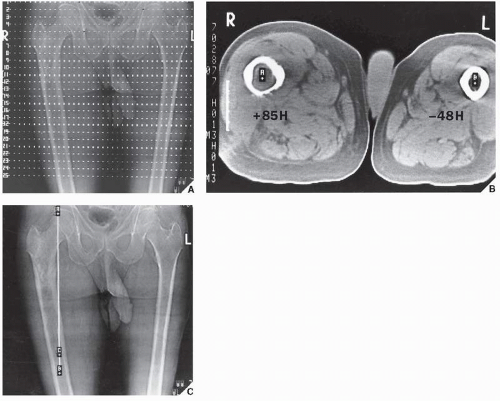 FIGURE 2.14 CT measurement of Hounsfield values. CT evaluation of intraosseous extension of chondrosarcoma is an important part of the radiologic workup of a patient if limb salvage is contemplated. (A) Several contiguous axial sections, preferably 1 cm in thickness, of affected and nonaffected limbs are obtained. (B) Hounsfield values of the bone marrow are measured to determine the distal extent of tumor in the medullary cavity. A value of +85H indicates the presence of tumor; a value of -48H is normal for fatty marrow. (C) The linear measurement is obtained from the proximal articular end of the bone A to the point located 5 cm distally to the tumor margin B. Point C corresponds to the most distal axial section that still shows tumor in the marrow. (From Greenspan A, 1989, with permission.) |
There are relatively few absolute contraindications to arthrography. Even hypersensitivity to iodine is a relative contraindication because, in this case, a single contrast study using only air can be performed.
Tenography and Bursography
Occasionally, to evaluate the integrity of a tendon, contrast material is injected into the tendon sheath. This procedure is known as a tenogram (see Figs. 10.13 and 10.72). Since the introduction of newer diagnostic modalities, such as CT and MRI, this procedure is seldom performed. It has relatively limited clinical application, mainly being used to evaluate traumatic or inflammatory conditions of the tendons (such as peroneus longus and brevis, tibialis anterior and posterior, and flexor digitorum longus) of the lower extremity and in the upper extremity to outline the synovial sheaths within the carpal tunnel.
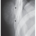
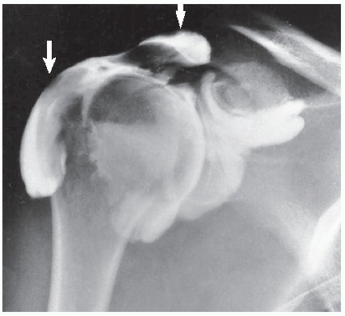 FIGURE 2.16 Shoulder arthrogram. After an injection of contrast into the glenohumeral joint, there is filling of subacromial-subdeltoid bursae complex (arrows), indicating rotator cuff tear. |
Stay updated, free articles. Join our Telegram channel

Full access? Get Clinical Tree


