to impaction or bayonet-type displacement (Figs. 7.11 and 7.12). CT scanning may provide additional information concerning the exact position of displaced fragments (Figs. 7.13, 7.14, 7.15).
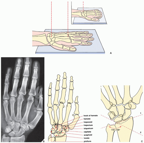 FIGURE 7.1 Dorsovolar (posteroanterior) view of the distal forearm, wrist, and hand. For the purpose of classification, a distinction is made between traumatic conditions involving the distal forearm, the wrist, and the hand. From a radiologic perspective, however, the positioning of the limb for posteroanterior and lateral films of the wrist area (i.e., the distal forearm and the carpus) and the hand is essentially the same. (A) For the posteroanterior (dorsovolar) view of the wrist and the hand, patients are seated with the arm fully extended on the radiographic table. The portion of the limb from the distal third of the forearm to the fingertips rests prone on the film cassette. Whether the wrist area or the hand is the focus of evaluation, the hand usually lies flat (palm down), with the fingers slightly spread. The point toward which the central beam is directed, however, varies. For the wrist, the beam is directed toward the center of the carpus; for the hand, the beam is directed toward the head of the third metacarpal bone. For better demonstration of the wrist area, the patient’s fingers may be flexed to cause the carpus to lie flat on the film cassette (inset). (B) On the radiograph obtained in this projection, the distal radius and the ulna, as well as the carpal and metacarpal bones and phalanges, are well demonstrated. The thumb, however, is seen in an oblique projection; the bases of the second to fifth metacarpals partially overlap. In the wrist, there is also overlap of the pisiform and the triquetrum, as well as the trapezium and trapezoid bones. (C) On this projection, a carpal angle can be determined. It is formed by two tangents, the first drawn against the proximal borders of the scaphoid and lunate (1) and the second drawn against the proximal borders of the triquetrum and lunate (2). The angle measures normally between 110 and 150 degrees, showing considerable deviation with age, gender, and race. |
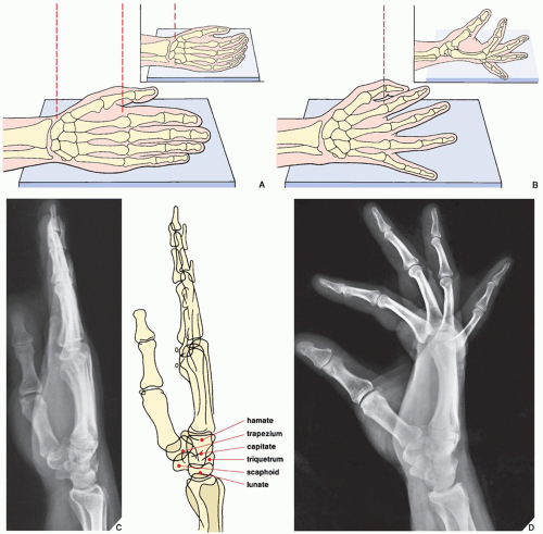 FIGURE 7.2 Lateral view of the wrist and hand. (A) For the lateral projection of the wrist area and the hand, the patient’s arm is fully extended and resting on its ulnar side. The fingers may be fully extended or, preferably, slightly flexed (inset), with the thumb slightly in front of the fingers. For the evaluation of the wrist area, the central beam is directed toward the center of the carpus, while for the hand, it is directed toward the head of the second metacarpal (B). On the radiograph obtained in this projection (C), the distal radius and the ulna overlap, but the relation of the longitudinal axes of the capitate, the lunate, and the radius can sufficiently be evaluated (see Fig. 7.84). Although the metacarpals and the phalanges also overlap, dorsal or volar displacement of a fracture of these bones can easily be detected (see Fig. 4.1). The thumb is imaged in true dorsovolar projection. A more effective way of imaging the fingers in the lateral projection is to have the patient spread the fingers in a fan-like manner, with the ulnar side of the fifth phalanx resting on the film cassette. The central beam is directed toward the heads of the metacarpals. (D) On the film in this projection, the overlap of the phalanges commonly seen on the standard lateral view is eliminated. The interphalangeal joints can readily be evaluated. |
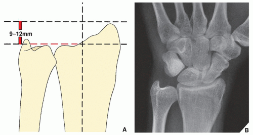 FIGURE 7.3 Neutral ulnar variance. (A) As a rule, the radial styloid process rises 9 to 12 mm above the articular surface of the distal ulna. This distance is also known as the radial length. (B) At the site of articulation with the lunate, the articular surfaces of the radius and the ulna are on the same level. |
 FIGURE 7.4 Negative and positive ulnar variance. (A) Negative ulnar variance. The articular surface of the ulna projects 5 mm proximal to the site of radiolunate articulation. (B) Positive ulnar variance. The articular surface of the ulna projects 8 mm distal to the site of radiolunate articulation. |
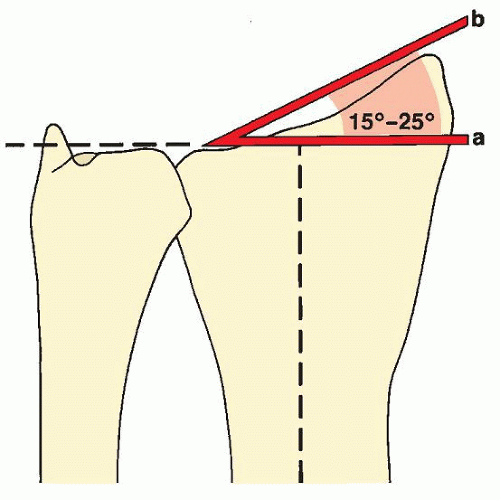 FIGURE 7.5 Ulnar slant. The ulnar slant of the articular surface of the radius is determined, with the wrist in the neutral position, by the angle formed by two lines: one perpendicular to the long axis of the radius at the level of the radioulnar articular surface (a) and a tangent connecting the radial styloid process and the ulnar aspect of the radius (b). |
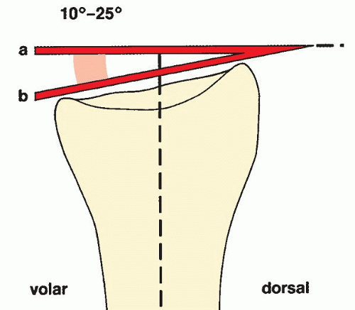 FIGURE 7.6 Palmar inclination. The palmar inclination of the radial articular surface is determined by measuring the angle formed by a line perpendicular to the long axis of the radius at the level of the styloid process (a) and a tangent connecting the dorsal and volar aspects of the radial articular surface (b). |
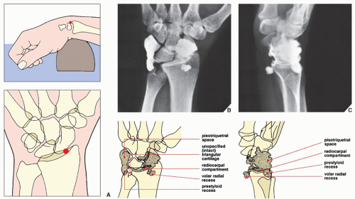 FIGURE 7.7 Arthrography of the wrist. (A) For arthrographic examination of the radiocarpal joint, the wrist is positioned prone on a radiolucent sponge to open the joint for needle insertion. Under fluoroscopic control, the joint is entered using a 22-gauge needle at a point lateral to the scapholunate ligament. (The red dot marks the site of puncture.) Two or 3 mL of contrast (60% diatrizoate meglumine) is injected, and posteroanterior (dorsovolar), lateral, and oblique films are obtained. Posteroanterior (B) and lateral (C) views show the contrast filling the radiocarpal compartment, the prestyloid and volar radial recesses, and the pisotriquetral space. Intact triangular fibrocartilage does not allow the contrast to enter the distal radioulnar joint, and intact intercarpal ligaments prevent a leak of contrast into the intercarpal articulations. |
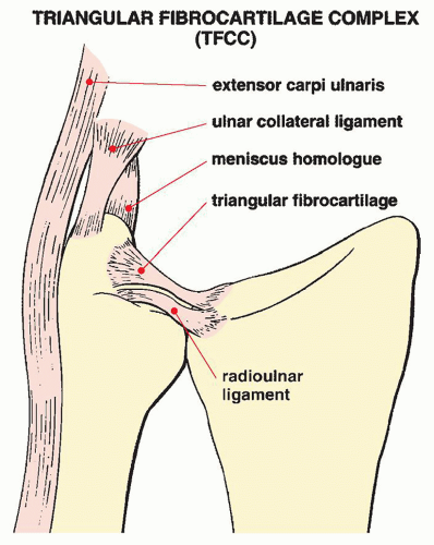 FIGURE 7.8 Triangular fibrocartilage complex. The TFCC includes the triangular fibrocartilage, radioulnar ligament, ulnocarpal ligament, extensor carpi ulnaris tendon and tendon sheath, and meniscus homolog. It is located between the distal ulna and the proximal carpal row, stabilizes the distal radioulnar joint, and functions as a cushion of compressing axial forces. The triangular fibrocartilage attaches medially to the fovea of the ulna and laterally to the lunate fossa of the radius. |
TABLE 7.1 Standard Radiographic Projections for Evaluating Injury to the Distal Forearm | ||||||
|---|---|---|---|---|---|---|
|
TABLE 7.2 Ancillary Imaging Techniques for Evaluating Injury to the Distal Forearm | ||||||||||
|---|---|---|---|---|---|---|---|---|---|---|
| ||||||||||
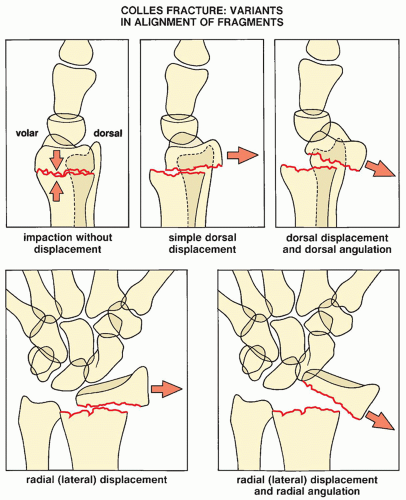 FIGURE 7.9 Colles fracture. Five variants of displacement and angulation of the distal fragment in Colles fracture. Some of these patterns may occur in combinations, yielding a complex deformity. |
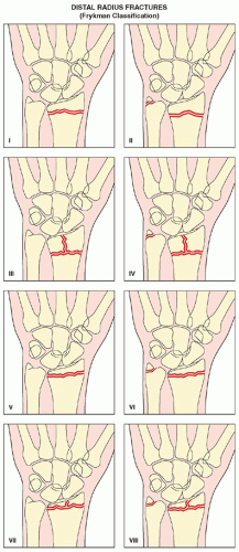 FIGURE 7.10 Distal radius fractures. Frykman classification of distal radius fractures according to the location of fracture line (intraarticular versus extraarticular) and association of distal ulna fracture. |
TABLE 7.3 Frykman Classification of Distal Radius Fractures | ||||||||||||||||||
|---|---|---|---|---|---|---|---|---|---|---|---|---|---|---|---|---|---|---|
| ||||||||||||||||||
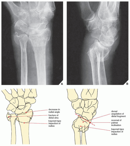 FIGURE 7.11 Colles fracture. Posteroanterior (A) and lateral (B) radiographs of the distal forearm demonstrate the features of Colles fracture. On the posteroanterior projection, a decrease in the radial angle and an associated fracture of the distal ulna are evident. The lateral view reveals the dorsal angulation of the distal radius as well as a reversal of the palmar inclination. On both views, the radius is foreshortened secondary to bayonet-type displacement. The fracture line does not extend to the joint (Frykman type II). |
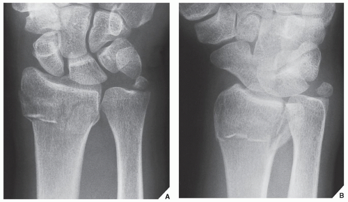 FIGURE 7.12 Intraarticular fracture of the distal radius. Posteroanterior (A) and oblique (B) radiographs of the distal forearm show Frykman type VI fracture. The fracture line extends into the distal radioulnar joint, and, in addition, there is a fracture of the ulnar styloid. |
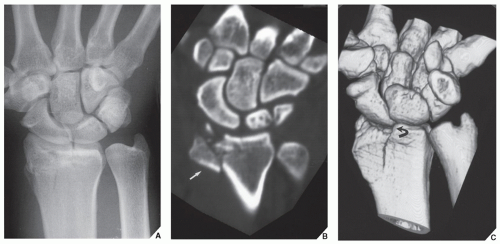 FIGURE 7.13 CT of an intraarticular fracture of the distal radius. (A) Posteroanterior radiograph of the wrist shows a fracture of the distal radius that appears to be nondisplaced. (B) Coronal reformatted and (C) 3D reconstructed CT images not only confirm the intraarticular extension of the fracture but also demonstrate displacement (arrow) and depression (curved arrow) of the fractured fragments. Because the distal radioulnar joint is spared and the ulna is intact, this injury represents Frykman type III fracture. |
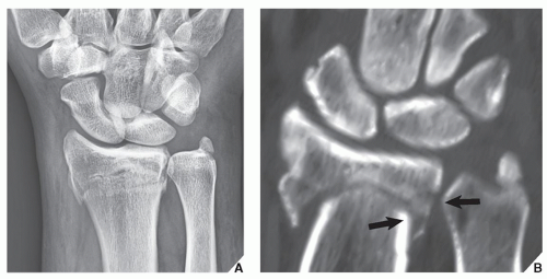 FIGURE 7.14 CT of an intraarticular fracture of the distal radius. (A) Posteroanterior radiograph of the wrist shows a fracture of the distal radius, but it is unclear if the fracture is extraarticular or intraarticular. In addition, there is a fracture of the styloid process of ulna. (B) Coronal reformatted CT image confirms that the fracture line extends into the distal radioulnar joint (arrows), but the radiocarpal joint is spared, thus rendering the diagnosis of Frykman type VI fracture. |
 FIGURE 7.15 CT of an intraarticular fracture of the distal radius. (A) Posteroanterior radiograph of the wrist shows an intraarticular fracture of the distal radius and a fracture of the ulnar styloid. (B) Coronal reformatted and (C) 3D reconstructed CT images clearly show an extension of the fracture lines into both the radiocarpal and the distal radioulnar joint compartments, confirming Frykman type VIII fracture. |
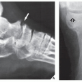
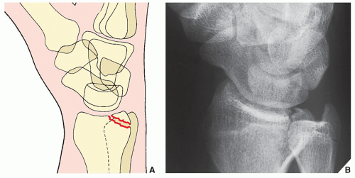 FIGURE 7.16 Barton fracture. Schematic (A) and oblique radiograph (B) show the typical appearance of Barton fracture. The fracture line in the coronal plane extends from the dorsal margin of the distal radius into the radiocarpal articulation. |
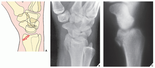 FIGURE 7.17 Reverse Barton fracture. Schematic (A), oblique radiograph (B), and lateral trispiral tomogram (C) show the reverse (or volar) Barton fracture; the fracture line is also oriented in the coronal plane but extends from the volar margin of the radial styloid process into the radiocarpal joint. |
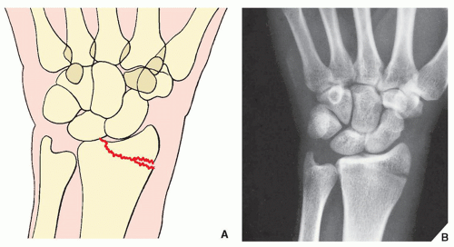 FIGURE 7.18 Hutchinson fracture. Schematic (A) and dorsovolar radiographs (B) showing classic appearance of Hutchinson fracture. The fracture line in the sagittal plane extends through the radial margin of the radial styloid process into the radiocarpal articulation. |
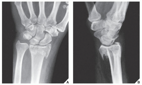 FIGURE 7.19 Smith fracture. Posteroanterior (A) and lateral (B) radiographs of the distal forearm show the typical appearance of Smith fracture. Volar displacement of the distal fragment is clearly evident on the lateral view. |
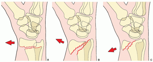 FIGURE 7.20 Smith fracture. The three types of Smith fracture are distinguished by the obliquity of the fracture line. Volar displacement of the distal fragment is characteristic of all three types. (A) In Smith type I, the fracture line is transverse, extending from the dorsal to the volar cortices of the radius. (B) The oblique fracture line in type II extends from the dorsal lip of the distal radius to the volar cortex. (C) Type III, which is almost identical to the reverse Barton fracture (see Fig. 7.17), is an intraarticular fracture with an extension to the volar cortex of the distal radius. |
 FIGURE 7.21 Galeazzi fracture-dislocation. Posteroanterior (A) and lateral (B) radiographs of the distal forearm show type I Galeazzi fracture-dislocation. The simple fracture of the radius affects the distal third of the bone, and the proximal end of the distal fragment is dorsally displaced and angulated. In addition, there is dislocation in the distal radioulnar joint. |
 FIGURE 7.22 Galeazzi fracture-dislocation. Posteroanterior (A), oblique (B), and lateral (C) radiographs of the distal forearm show a variant of type I injury, where the distal fragment of the radius is volarly displaced and medially angulated. Note that the distal ulna is protruding through the skin (arrows). |
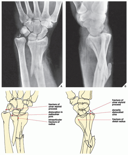 FIGURE 7.23 Galeazzi fracture-dislocation. Posteroanterior (A) and lateral (B) projections of the distal forearm demonstrate the two components of Galeazzi fracture-dislocation type II. The posteroanterior radiograph clearly reveals the fracture of the distal radius, which, in this case, is comminuted, extending into the radiocarpal joint. The distal fragment has a slight lateral angulation. Note also the associated comminuted fracture of the ulnar styloid process and the dislocation in the radioulnar joint. These features are also seen on the lateral projection, but this view provides in addition a better demonstration of the dorsal dislocation of the distal ulna. |
 FIGURE 7.24 Piedmont fracture. (A) Anteroposterior radiograph of the forearm shows a typical appearance of the Piedmont fracture, an isolated fracture at the junction of the middle and distal thirds of the radius, necessitating an open reduction and internal fixation (B). |
such as those described in the preceding sections or independently after an injury to the distal forearm and wrist.
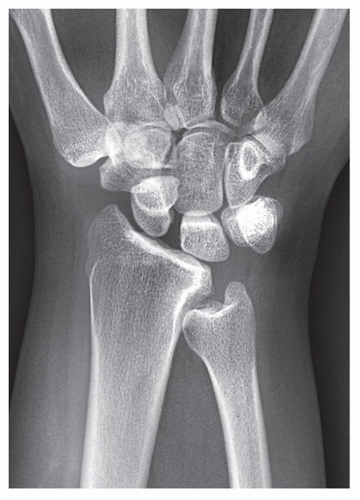 FIGURE 7.25 Ulnar impingement syndrome. Posteroanterior radiograph of the wrist shows a negative ulnar variance. The distal ulna impinges on the medial cortex of distal radius. |
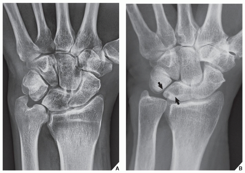 FIGURE 7.26 Ulnar impaction syndrome. (A) Posteroanterior radiograph of the wrist shows a positive ulnar variance. The ulnolunate interval is significantly decreased, and there is sclerosis of the distal ulna and medial aspect of the lunate. (B) In another patient, note the cystic changes in the lunate (arrows). |
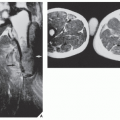
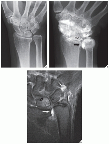 FIGURE 7.27 Arthrography and MRI of the ulnar impaction syndrome. (A) Conventional radiograph of the wrist shows a positive ulnar variance, but there are no other appreciated abnormalities seen. (B) Wrist arthrogram shows a tear of the TFCC (arrow) and a tear of the lunotriquetral ligament (open arrow). (C) Coronal T2-weighted fat-suppressed MR arthrographic image shows contrast in the distal radioulnar joint (arrow), confirming the diagnosis of a tear of TFCC, and cystic changes and edema of the lunate (open arrows), confirming the diagnosis of ulnar impaction syndrome. |
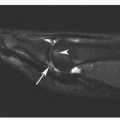
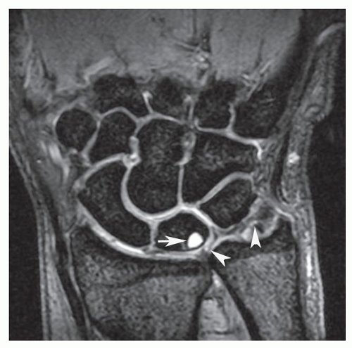 FIGURE 7.28 MRI of the ulnar impaction syndrome. Coronal gradient recalled echo (GRE) MR image demonstrates ulnar positive variance. There is a complete tear of the TFCC (arrowheads) and subchondral cyst in the ulnar aspect of the lunate (arrow). |
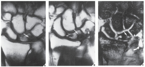 FIGURE 7.29 MRI of the ulnar impaction syndrome. (A) Coronal T1-weighted MR image shows a positive ulnar variance and sclerosis of the proximal ulnar aspect of the lunate (arrow). (B) Coronal T1-weighted MRI obtained slightly more volarly and (C) corresponding T2*-weighted image demonstrate subchondral cysts (straight arrows) and involvement of triquetrum (small curved arrows). Note also the disruption of the triangular fibrocartilage (large curved arrow). (From Stoller DW. MRI in orthopaedics and sports medicine. Philadelphia: JB Lippincott; 1993.) |
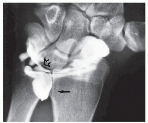 FIGURE 7.30 Arthrography of a TFCC tear. A single-contrast arthrogram of the wrist shows a leak of contrast into the space occupied by the triangular cartilage (open arrow), with characteristic filling of the distal radioulnar compartment (arrow), confirming a tear of the TFCC (compare with Fig. 7.7B). |
lunate bones (Fig. 7.31; see also Fig. 7.8). Tears of the TFCC manifest as discontinuities and fragmentation of this structure. The torn fibrocartilage becomes irregular in contour and is interrupted by high-signal intensity areas on T2-weighted images (Fig. 7.32). However, one of the studies published by Haims and colleagues questions the sensitivity of MRI in diagnosing peripheral tears of the triangular fibrocartilage. In this respect, the authors reported the sensitivity of MRI of only 17%, with a specificity of 79%, and accuracy of 64%.
 FIGURE 7.31 MRa of the wrist. Coronal T1-weighted fat-suppressed MR arthrographic image of the wrist shows a normal appearance of the TFCC (arrow). |
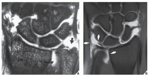 FIGURE 7.32 MRI of the tear of the TFCC. (A) Coronal T2*-weighted gradient-recalled acquisition in the steady state (GRASS) image of the left wrist shows a fullthickness tear of the TFCC. The triangular fibrocartilage is torn and displaced from the ulnar styloid (arrow). Moderate amount of fluid is seen in the distal radioulnar joint (curved arrow). (B) In another patient, coronal proton density-weighted fat-suppressed arthrographic MR image of the wrist shows a tear of the TFCC (arrows). (A, From Deutsch AL, Mink JH, eds. MRI of the musculoskeletal system: a teaching file, 2nd ed. Philadelphia: Lippincott-Raven Publishers; 1997.) |
Dorsovolar obtained in ulnar deviation of the wrist for the evaluation of the scaphoid bone, which appears foreshortened on the standard dorsovolar projection as a result of its normal volar tilt (Fig. 7.33)
Supinated oblique for visualizing the pisiform bone and the pisotriquetral joint (Fig. 7.34)
Pronated oblique for imaging the triquetral bone, the radiovolar aspect of the scaphoid, and the radial styloid process (Fig. 7.35)
Carpal tunnel for demonstrating the hook of the hamate, the pisiform, and the volar aspect of the trapezium (Fig. 7.36)
combined with arthrography (see Fig. 2.19) or can be enhanced by an intravenous contrast material. It is effective in demonstrating subluxation in the distal radioulnar joint and in evaluating the so-called humpback deformity of the scaphoid, osteonecrosis of the lunate (Kienböck disease), and fractures of the hook of the hamate, among other abnormalities. Axial sections are obtained after positioning the patient prone with the arm extended above the head. Contiguous sections of 1 or 2 mm are acquired, preferably using a spiral (helical) technique. Direct coronal sections can also be obtained with the wrist in maximal volar flexion or dorsal extension.
 FIGURE 7.33 Ulnar deviation. (A) For the dorsovolar view of the wrist in ulnar deviation, the forearm rests flat on the radiographic table with the anterior surface down and the elbow flexed 90 degrees. The hand, lying flat on the film cassette, is ulnarly deviated. The central beam is directed toward the carpus. (B) The radiograph in this projection demonstrates the scaphoid free of the distortion because of its normal volar tilt when the wrist is in the neutral position. |
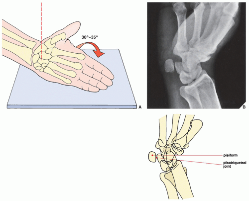 FIGURE 7.34 Supinated oblique view. (A) For the supinated oblique view of the wrist, the hand resting on its ulnar side on the film cassette is tilted approximately 30 to 35 degrees toward its dorsal surface. The outstretched fingers are held together, with the thumb slightly abducted. The central beam is directed toward the center of the wrist. (B) The radiograph in this projection demonstrates the pisiform bone and the pisotriquetral joint. |
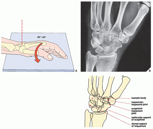 FIGURE 7.35 Pronated oblique view. (A) For the pronated oblique view of the wrist, the hand resting on its ulnar side on the film cassette is tilted approximately 40 to 45 degrees toward its palmar surface. The slightly flexed fingers are held together, with the thumb in front of them. The central beam is directed toward the center of the carpus. (B) The radiograph in this projection demonstrates the dorsal aspect of the triquetrum, the body of the hamate, the radiovolar aspect of the scaphoid, and the scaphoid-trapezium and trapezium-trapezoid articulations. |
 FIGURE 7.36 Carpal tunnel view. (A) For the carpal tunnel view of the wrist, the hand is maximally dorsiflexed by means of the patient’s opposite hand or a strap, with the palmar surface of the wrist resting on the film cassette. The central beam is directed toward the cup of the palm at approximately an angle of 15 degrees. (B) The radiograph in this projection demonstrates an axial view of the hook of the hamate as well as the pisiform bone and the volar margin of the trapezium. |
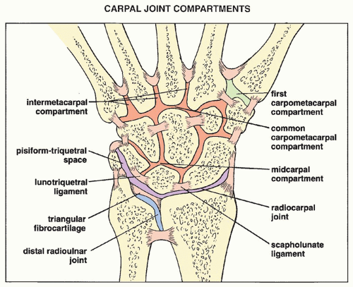 FIGURE 7.37 Compartments of the carpus. Carpal joint compartments are separated from one another by various interosseous ligaments. |
view is recommended. This technique may image not only abnormalities of the soft tissues, including various muscles, tendons, interosseous ligaments, and triangular fibrocartilage, but also osseous abnormalities such as occult fractures and early osteonecrosis, particularly of the lunate and scaphoid. It is also very useful in imaging the carpal tunnel (Fig. 7.39) and detecting the subtle abnormalities of carpal tunnel syndrome (Fig. 7.40; see also Fig. 7.115) and Guyon canal syndrome (see Fig. 7.116). Commonly, MRI is performed after an intraarticular injection of a contrast agent (diluted gadolinium) into the radiocarpal compartment (see Fig. 7.31).
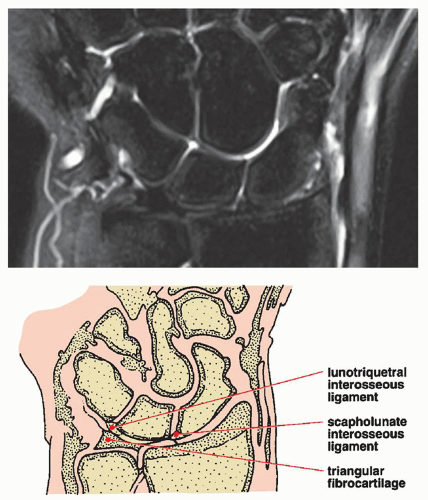 FIGURE 7.38 MRI of the wrist. Coronal T2-weighted fat-saturated MR image of the wrist demonstrates distal radius and ulna and carpal bones. The proximal interosseous ligaments and the triangular fibrocartilage are clearly delineated. |
 FIGURE 7.39 MRI of the wrist. T1-weighted axial MR image through the carpal tunnel demonstrates the various structures. Note the median nerve, displaying intermediate signal intensity and flexor retinaculum imaged with low signal intensity. |
 FIGURE 7.40 MRI of carpal tunnel syndrome. Axial short time inversion recovery (STIR) MR image in a patient with carpal tunnel syndrome demonstrates high signal intensity of the median nerve (arrow) and bowing of the flexor retinaculum (arrowheads). |
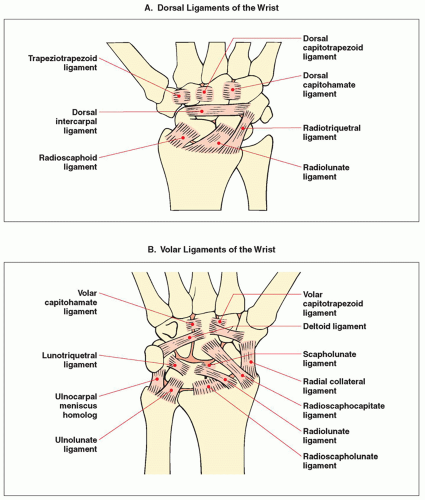 FIGURE 7.41 Ligaments of the wrist. A schematic representation of the dorsal (A) and volar (B) ligaments of the wrist. |
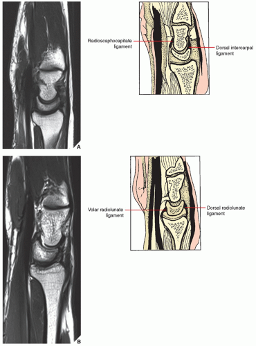 FIGURE 7.42 MRI of the wrist. Sagittal MRI through the wrist from the midaspect (A,B) to the ulnar aspect (C,D). The volar and dorsal radiolunate components of the radioscapholunate ligaments are well demonstrated. The radiolunotriquetral ligament is seen volar to the capitate-lunate articulation. The radioscaphocapitate ligament is seen inserting at the volar and proximal one third of the capitate bone.
Related posts: Radiologic Evaluation of Skeletal Anomalies Radiologic Evaluation of Skeletal Anomalies
 Inflammatory Arthritides Inflammatory Arthritides
 Benign Tumors and Tumor-like Lesions II: Lesions of Cartilaginous Origin Benign Tumors and Tumor-like Lesions II: Lesions of Cartilaginous Origin
 Benign Tumors and Tumor-Like Lesions III: Fibrous, Fibroosseous, and Fibrohistiocytic Lesions Benign Tumors and Tumor-Like Lesions III: Fibrous, Fibroosseous, and Fibrohistiocytic Lesions
 Anomalies of the Upper and Lower Limbs Anomalies of the Upper and Lower Limbs
 Radiologic Evaluation of Trauma Radiologic Evaluation of Trauma
Stay updated, free articles. Join our Telegram channel
Full access? Get Clinical Tree
 Get Clinical Tree app for offline access

|