Conventional radiography, including routine views (specific for various body parts), special views, and stress views
Digital radiography, including digital subtraction arthrography (DSa) and angiography (DSA).
Fluoroscopy, alone or combined with videotaping
Computed tomography (CT)
Arthrography, tenography, and bursography
Myelography and diskography
Angiography (arteriography and venography)
Scintigraphy (radionuclide bone scan)
Ultrasonography (US)
Magnetic resonance imaging (MRI)
tibialis anterior and posterior, and flexor digitorum longus. Bursography of the subacromial-subdeltoid bursae complex occasionally demonstrated a partial or full-thickness tear of the rotator cuff.
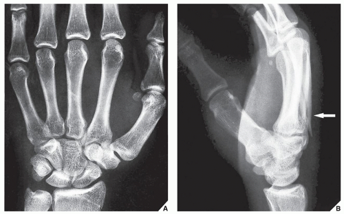 FIGURE 4.1 Fracture of the metacarpal bone in an adult. (A) Dorsovolar (posteroanterior) radiograph of the hand does not demonstrate a fracture. (B) The lateral radiograph reveals a fracture of the third metacarpal bone (arrow). |
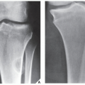
 FIGURE 4.2 Fracture of the tibia in a child. (A) Anteroposterior radiograph of the leg of a 3-year-old boy shows no abnormalities. (B) The lateral radiograph demonstrates a nondisplaced oblique fracture of the tibia (arrow). |
 FIGURE 4.3 Fracture of the radial head. A patient presented with elbow pain after a fall. Anteroposterior (A) and lateral (B) radiographs are normal; however, the radial head and coronoid processes are not well demonstrated because of a bony overlap. A special 45-degree angle view of the elbow (C) is used to project the radial head ventrad, free of the overlap of other bones. A short, intraarticular fracture of the radial head is now clearly visible (arrow). |
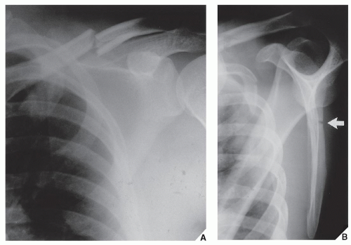 FIGURE 4.4 Fracture of the scapula. (A) Anteroposterior radiograph of the left shoulder shows a fracture of the clavicle. An injury to the scapula is not well demonstrated. (B) A special “Y” view of the scapula clearly shows the fracture (arrow). |
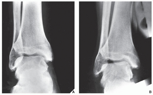 FIGURE 4.5 Tear of the lateral collateral ligament. In most ankle injuries, if a ligamentous tear is suspected, then conventional films may be supplemented by stress views. The standard anteroposterior radiograph of this ankle (A) is not remarkable. The same view after the application of adduction (inversion) stress (B) shows a widening of the lateral compartment of the tibiotalar (ankle) joint, indicating a tear of the lateral collateral ligament. |
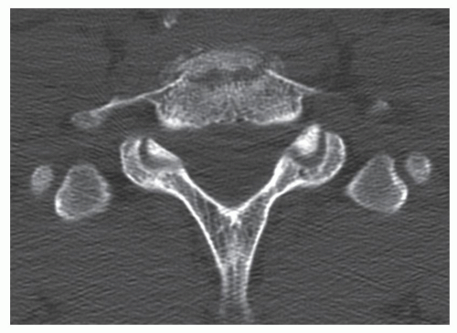 FIGURE 4.6 Fracture of the vertebra. Conventional radiographs of the cervical spine (not shown here) were suggestive but not conclusive of a fracture of C7 vertebral body, which is, however, clearly demonstrated on this axial CT image. |
 FIGURE 4.7 Fracture of the sacrum. (A) Standard anteroposterior radiograph of the pelvis shows obvious fractures of the right obturator ring. (B) CT section demonstrates an unsuspected fracture of the sacrum and disruption of the left sacroiliac joint. |
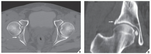 FIGURE 4.8 Fracture of the acetabulum. (A) Axial and (B) coronal CT reformatted images show a fractured fragment, unsuspected on conventional radiographs, displaced into the right hip joint. The arrows point to the fracture of the posterior column of the right acetabulum. |
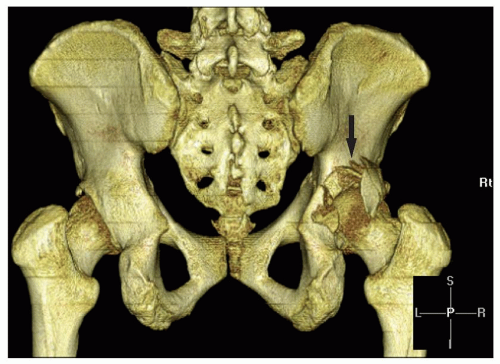 FIGURE 4.9 Fracture of the acetabulum. 3D CT reconstructed image shows distinctive features of a fracture of the posterior wall of the right acetabulum (arrow). |
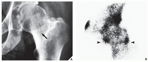 FIGURE 4.10 Fracture of the femoral neck. (A) Anteroposterior view of the left hip reveals a band of increased density (arrow), suggesting a fracture of the femoral neck. (B) A bone scan performed after the administration of 15 mCi (555 MBq) of 99mTC-labeled MDP shows increased uptake of isotope in the region of the femoral neck (arrowheads), confirming the fracture. |
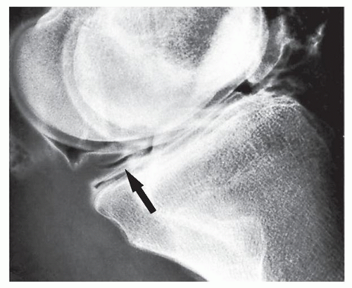 FIGURE 4.11 Tear of the medial meniscus. In this patient, double-contrast arthrography of the knee shows a horizontal cleavage tear in the posterior horn of the medial meniscus (arrow). |
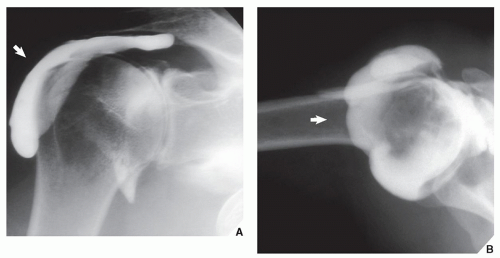 FIGURE 4.12 Tear of the rotator cuff. Anteroposterior (A) and axillary (B) radiographs obtained after single-contrast arthrogram of the right shoulder was performed show a leak of contrast into the subacromial-subdeltoid bursae complex (arrows) diagnostic of a full-thickness tear of the supraspinatus tendon. |
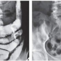
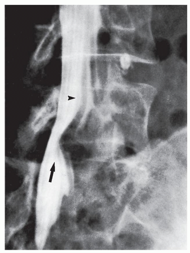 FIGURE 4.13 Herniation of the lumbar disk. A patient strained his back by lifting a heavy object. An oblique view of the lower lumbosacral spine after an injection of metrizamide contrast into the subarachnoid space shows an extradural pressure defect on the thecal sac at the L5-S1 intervertebral space (arrow) characteristic of disk herniation. Note the markedly swollen, displaced nerve root (arrowhead). |
arthroscopies are avoided. MRI is probably the only imaging modality that can demonstrate so-called bone contusions (see Fig. 2.39). These abnormalities consist of posttraumatic marrow change resulting from a combination of hemorrhage, edema, and microtrabecular injury. Meniscal injuries, such as bucket-handle tears, tears of the free edge, and peripheral detachments, can be accurately diagnosed. Other subtle abnormalities of various structures and posttraumatic joint effusion can also be well visualized (Figs. 4.16 and 4.17). Similarly, the medial and lateral collateral ligaments, anterior and posterior cruciate ligaments, and tendons around the knee joint can be well demonstrated (see Figs. 9.14 and 9.15) and abnormalities of these structures can be diagnosed with high accuracy. In the shoulder, impingement syndrome and complete and incomplete rotator cuff tears may be effectively diagnosed most of the time (Fig. 4.18). Traumatic lesions of the tendons (such as biceps tendon rupture), traumatic joint effusions, and hematomas are easily diagnosed with MRI. Likewise, this modality is effective to diagnose a tear of the cartilaginous labrum. The
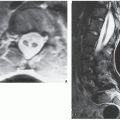
changes of osteonecrosis at various sites, particularly in its early stage, may be detected by MRI when other modalities, such as conventional radiography and even radionuclide bone scan, may be normal. MRI of the ankle and foot has been used among others in diagnosing tendon ruptures and posttraumatic osteonecrosis of the talus. In the wrist and hand, MRI has been successfully used in the early diagnosis of posttraumatic osteonecrosis of the scaphoid and Kienböck disease. MRI is strongly advocated as the technique of choice in the evaluation of abnormalities of the triangular fibrocartilage complex, although arthrography, particularly in conjunction with digital imaging and CT, is also a very effective modality. The greatest use of MRI is for evaluating trauma of the spine, the spinal cord, the thecal sac, and nerve roots, as well as for evaluating disk herniation (see Fig. 11.105). MRI is also useful in the evaluation of spinal ligament injuries. The demonstration of the relationship of vertebral fragments to the spinal cord with direct sagittal imaging is extremely helpful, particularly to evaluate injuries in the cervical and thoracic areas.
 FIGURE 4.14 Rupture of the annulus fibrosus and disk herniation. A spinal needle was placed in the center of the nucleus pulposus and a few milliliters of metrizamide were injected. The leak of contrast into the extradural space (arrow) indicates a tear of the annulus fibrosus and posterior disk herniation. |
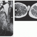
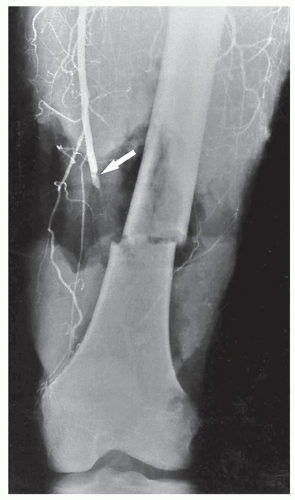 FIGURE 4.15 Tear of the femoral artery. A femoral arteriogram was performed to rule out damage to vascular structures by a fractured femur. Transverse fracture of the distal femur resulted in transsection of the superficial femoral artery (arrow). |
 FIGURE 4.16 Chondral defects. Axial proton density-weighted fat-saturated MRI of the knee demonstrates subtle defects in the articular cartilage of the right patella (arrows). |
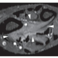
 FIGURE 4.17 Joint effusion and a tear of the patellar retinaculum. (A) A young man sustained a twisting injury to the knee. Axial short time inversion recovery (STIR) pulse sequence MR image demonstrates hemarthrosis with a fluid-fluid level (long arrow), bone contusion of the lateral femoral condyle (arrowheads), osteochondral fracture of the medial facet of the patella (arrowhead), and rupture of the medial patellofemoral ligament (a component of the medial patellar retinaculum) at the patellar and femoral insertions (short arrows). (B) A 33-year-old woman injured her right knee in a ski accident. Axial proton density-weighted fat-suppressed MRI shows a tear of the medial retinaculum of the patella (arrow). The lateral retinaculum is intact (arrowheads). A curved arrow points to posttraumatic joint effusion. |
 FIGURE 4.18 Tear of the rotator cuff. A 56-year-old man presented with right shoulder pain. Oblique coronal T1-weighted fat-suppressed MR arthrogram demonstrates a full-thickness rotator cuff tear. The supraspinatus tendon is retracted medially (arrow) and no tendon tissue is present in the subacromial space. |
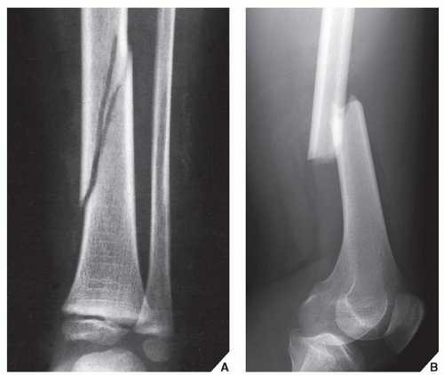 FIGURE 4.19 A complete fracture. (A) The continuity of the bone (tibia) is disrupted and there is a narrow gap between the bone fragments. (B) A complete fracture of the femur in an adult patient. |
Diagnosing and evaluating the type of fracture or dislocation
Monitoring the results of treatment and looking for possible complications
to the longitudinal axis of the bone (Fig. 4.27); (e) the presence of special features such as impaction, depression, or compression (Fig. 4.28); (f) the presence of associated abnormalities such as a fracture with concomitant dislocation or diastasis (Fig. 4.29); and (g) special types of fractures that may occur as the result of abnormal stress or secondary to pathologic processes in the bone (Fig. 4.30). The distinction between an open (or compound) fracture, one in which the fractured bone communicates with the outside environment through an open wound (Fig. 4.31), and a closed (or simple) fracture, one that does not produce an open wound in the skin, should preferably be made by clinical rather than radiographic examination.
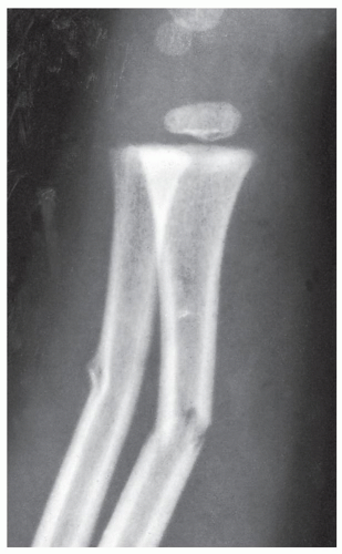 FIGURE 4.20 An incomplete (greenstick) fracture. The ulna is bent and there is a fracture line extending only through the posterior cortex. In the fracture of the radius, some trabeculae remain intact. |
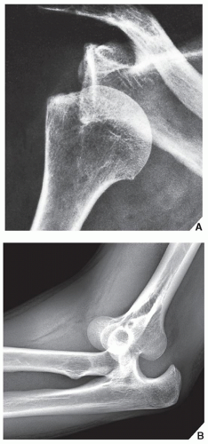 FIGURE 4.21 Dislocation. (A) Typical anterior dislocation of the humeral head. The articular surface of the humerus loses contact with the articular surface of the glenoid. (B) Typical posterior dislocation in the elbow joint. |
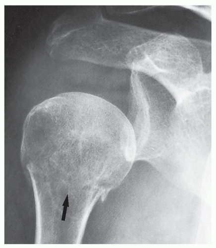 FIGURE 4.22 Subluxation. There is malalignment of the head of the humerus and the glenoid fossa, but some articular contact remains. Note the associated fracture of the surgical neck of the humerus (arrow). |
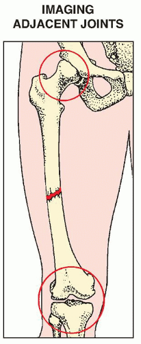 FIGURE 4.23 Adjacent joints. The radiograph of a suspected fracture of the femoral shaft should include the hip and knee articulations. |
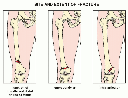 FIGURE 4.24 Site and extent. Factors in the radiographic evaluation of a fracture: the anatomic site and extent. |
 FIGURE 4.25 Incomplete and complete fractures. Factors in the radiographic evaluation of a fracture: the type of fracture—incomplete or complete. |
 FIGURE 4.26 Alignment. Factors in the radiographic evaluation of a fracture: the alignment of the fragments. |
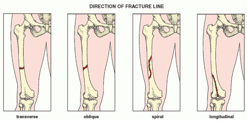 FIGURE 4.27 Direction. Factors in the radiographic evaluation of a fracture: the direction of the fracture line. |
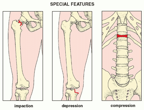 FIGURE 4.28 Special features. Factors in the radiographic evaluation of a fracture: special features. |
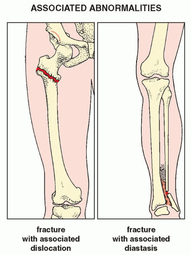 FIGURE 4.29 Associated abnormalities. Factors in the radiographic evaluation of a fracture: associated abnormalities. |
 FIGURE 4.30 Special types. Factors in the radiographic evaluation of a fracture: special types of fractures. |
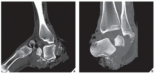 FIGURE 4.31 Open (compound) fracture. Reformatted sagittal (A) and coronal (B) CT images show a fracture/dislocation in the ankle and subtalar joints. Note communication of the fracture fragments with outside environment. |
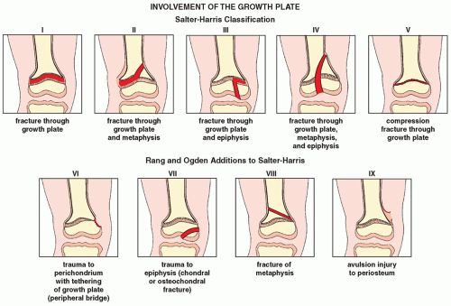 FIGURE 4.32 Classification of the growth plate injuries. The Salter-Harris classification of injuries involving the growth plate (physis) together with Rang and Ogden additions. |
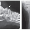
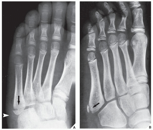 FIGURE 4.33 Fracture versus ossification center. (A) Dorsoplantar view of the foot reveals prominent soft-tissue swelling localized in the lateral aspect (arrowhead). The radiolucent line at the base of the fifth metatarsal indicates a fracture (arrow). (B) A similar radiolucent line (arrow) separates a bone fragment from the base of the fifth metatarsal in another patient who was suspected of sustaining a fracture of this bone. Note the complete lack of soft-tissue swelling. The finding represents a secondary ossification center, not a fracture. |
 FIGURE 4.34 Pronator quadratus fat stripe. (A) The fascial plane of the pronator quadratus is demonstrated on the volar aspect of the distal forearm as a radiolucent stripe. (B) With a fracture of the distal radius, the fat stripe is blurred and volarly displaced (arrow) secondary to local edema and periosteal hemorrhage. A short black arrow points to the subtle nondisplaced fracture of the distal radius. |
 FIGURE 4.35 Scaphoid fat stripe. (A) Normal scaphoid fat stripe (arrow). (B) A subtle fracture of the scaphoid (arrow) resulted in obliteration and radial displacement of the fat stripe (white arrow). |
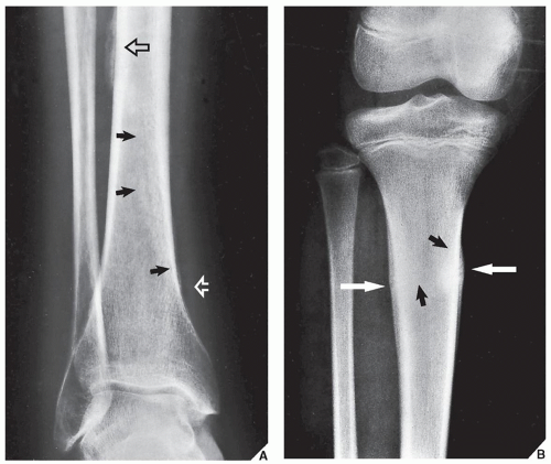 FIGURE 4.36 Secondary signs of a fracture. (A) A 49-year-old woman sustained an injury to the lower leg. Anteroposterior radiograph shows periosteal new bone at the medial cortex of the distal third of the tibia just above the malleolus and more proximally at the lateral aspect (open arrows). This indirect sign of a fracture represents an early stage of external callus formation. The actual hairline spiral fracture line is barely discernible (black arrows). (B) An example of periosteal callus formation at the medial and lateral cortices of the proximal tibial diaphysis (arrows). A transverse band of increased density, visible in the medullary portion of the bone (black arrows), represents endosteal callus. The fracture line is practically invisible. These features are commonly seen in a stress fracture. |
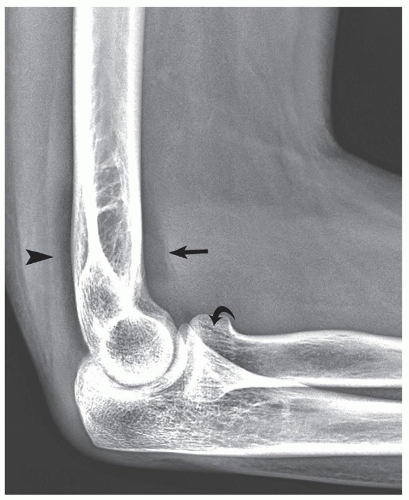 FIGURE 4.37 Fracture of the radial head. Lateral view of the elbow shows a positive fat-pad sign. The anterior fat pad is markedly elevated (arrow) and the posterior fat pad (arrowhead) is clearly visible in this patient. There is a subtle, nondisplaced fracture of the radial head (curved arrow). |
 FIGURE 4.38 Fat-blood interface sign. (A) Erect anteroposterior view of the shoulder demonstrates the fat-fluid level in the joint (arrow), an example of the FBI sign. The fracture line extends from the humeral neck cephalad to the greater tuberosity (arrowheads). To demonstrate the FBI sign, the cassette should be positioned perpendicular to the expected fat-fluid level with the central ray directed horizontally. For example, in the shoulder, an upright radiograph (patient standing or sitting) should be obtained. In the knee (B), the patient must be supine and a cross-table lateral view should be performed. |
and compact bone. For the radiologist evaluating follow-up radiographs, the primary indication of bone repair is radiographic evidence of periosteal (external) and endosteal (internal) callus formation (Fig. 4.45). This process, however, may not be radiographically apparent in the early stage of healing. Periosteal response may not be visible on radiographs at sites where there is an anatomic lack of periosteum, for example, in the intracapsular portion of the femoral neck. Likewise, radiographs may not demonstrate endosteal callus formation because the callus contains only fibrous tissue and cartilage, which are radiolucent. At this early stage of healing, a fracture may be clinically united, that is, shows no evidence of motion under stress, yet radiographically, the radiolucent band between the fragments may persist (Fig. 4.46A). As the primary temporarily radiolucent callus is gradually converted by the process of endochondral ossification to more mature lamellar bone, it is seen on the film as a dense bridge (Fig. 4.46B). This constitutes radiographic union.
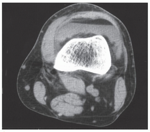 FIGURE 4.39 FBI sign on CT. Axial CT section through the knee joint shows an FBI sign in a patient with tibial plateau fracture (not seen on this image). |
 FIGURE 4.40 FBI sign on MRI. Axial proton density-weighted fat-saturated MR image of the knee with the patient in the supine position demonstrates an FBI sign secondary to differential layering of fat (low signal intensity) floating on top of blood (intermediate signal intensity) (arrows), representing lipohemarthrosis. |
 FIGURE 4.41 Fracture of the femur. (A) On the anteroposterior radiograph of the knee, the fracture line is not apparent, but a depressed articular cortex of the lateral femoral condyle projects proximally to the normal subchondral line of the intact segment, producing a double cortical line (arrow). (B) Lateral radiograph confirms the presence of a depressed fracture of the femoral condyle (arrow). |
 FIGURE 4.42 Torus fracture. Posteroanterior (A) and lateral (B) radiographs of the distal forearm demonstrate buckling of the dorsal cortex of the diaphysis of the distal radius (arrows). This represents an incomplete torus fracture. Note that the lateral view is more revealing. |
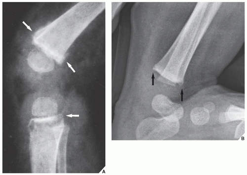 FIGURE 4.43 Battered child syndrome. (A) Lateral radiograph of the knee reveals irregular outlines of the metaphyses of the distal femur and the proximal tibia and subtle corner fractures (arrows) characteristic of the battered child syndrome. (B) In another infant, metaphyseal corner fractures are identified in the distal tibia (arrows). |
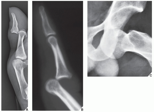 FIGURE 4.44 Dislocations. (A) Lateral radiograph of the thumb shows a dislocation in the interphalangeal joint. (B) Lateral radiograph shows a dislocation in the proximal interphalangeal joint of the index finger. (C) Anteroposterior radiograph of the left hip shows a typical anterior dislocation of the femoral head. The clue to this diagnosis is the presence of abduction and external rotation of the femur and the position of the femoral head, which is medial and inferior to the acetabulum. |
TABLE 4.1 Factors Influencing Fracture Healing | ||||||||||||||||||||||||
|---|---|---|---|---|---|---|---|---|---|---|---|---|---|---|---|---|---|---|---|---|---|---|---|---|
|
TABLE 4.2 Fracture Healing | |||||||||||||||||||
|---|---|---|---|---|---|---|---|---|---|---|---|---|---|---|---|---|---|---|---|
|
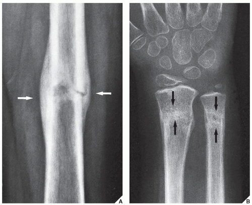 FIGURE 4.45 Fracture healing. (A) Anteroposterior radiograph of the femur shows a fracture healing predominantly by periosteal callus formation (arrows). There is no radiographic evidence of endosteal callus, and the fracture line is still visible. (B) Posteroanterior radiograph of the distal forearm demonstrates healing fractures of the radius and ulna. The fracture lines are almost completely obliterated secondary to the formation of endosteal callus (arrows). Note also the minimal amount of periosteal callus. |
 FIGURE 4.46 Clinical versus radiographic union. A 30-year-old woman sustained a fracture of the distal third of the tibia. (A) After 3 months of immobilization, the plaster cast was removed. The radiograph shows a unilateral periosteal callus from the medial aspect, but the fracture line is still clearly visible. Clinically, however, this fracture was fully united and the patient was allowed to bear weight without a cast. (B) One and a half months later, there is evidence of a dense bridge of periosteal and endosteal callus, indicating radiographic union. |
 FIGURE 4.47 Malunion. (A) Anteroposterior radiograph of the leg demonstrates angular malunion. The fracture of the tibia and the segmental fracture of the fibula are solidly united. The distal part of the tibia, however, shows rotation and anterior angulation, and the fractures of the fibula have joined in a bowing deformity. (B) The malunion was surgically treated by double osteotomy and internal fixation of the tibia with an intramedullary rod to correct the longitudinal alignment and restore the anatomic axis. |
 FIGURE 4.48 Nonunion. A fracture of the proximal fibula failed to unite. Note the gap between the fragments, the complete lack of callus formation, and the rounding of the fragment edges. |
TABLE 4.3 Causes of Nonunion | ||||||||||||||||||||||||||||||||||||||
|---|---|---|---|---|---|---|---|---|---|---|---|---|---|---|---|---|---|---|---|---|---|---|---|---|---|---|---|---|---|---|---|---|---|---|---|---|---|---|
| ||||||||||||||||||||||||||||||||||||||
Related posts:
 Radiologic Evaluation of Skeletal Anomalies
 Inflammatory Arthritides
 Benign Tumors and Tumor-like Lesions II: Lesions of Cartilaginous Origin
 Benign Tumors and Tumor-Like Lesions III: Fibrous, Fibroosseous, and Fibrohistiocytic Lesions
 Anomalies of the Upper and Lower Limbs
 Upper Limb III: Distal Forearm, Wrist, and Hand
Stay updated, free articles. Join our Telegram channel

Full access? Get Clinical Tree


