Imaging Thoracolumbar Spine Trauma


Imaging Thoracolumbar Spine Trauma


Mark P. Bernstein

Alexander B. Baxter

John H. Harris Jr.


INTRODUCTION


Epidemiology

Motor vehicle crashes, falls, violence, and sportsrelated injuries contribute to 12,000 new spinal cord injuries each year in the United States. More than 80% of spinal cord injury victims are male, with an average age of 40 years. Forty-four percent of thoracolumbar spine fractures are associated with spinal cord injuries, and spinal cord injuries complicate 10% to 30% of all traumatic spinal fractures.

Four percent to 18% of blunt trauma victims suffer thoracolumbar spine fractures and these are often associated with major injuries in the head, chest, abdomen, pelvis, and extremities. Up to 25% of patients with spinal fractures and dislocations have multilevel injuries, as do 1.3% of spinal cord injury patients.

Half of all major spine injuries are unrecognized in the prehospital setting. Once in hospital, clinical diagnosis during the initial trauma resuscitation and evaluation may be challenged by altered consciousness, intoxication, and distracting injuries. Hasler et al., in a European cohort study of 24,000 spine fractures identified in more than 250,000 adult major trauma patients, determined predictors for spinal fracture.1 These were age younger than 45 years, Glasgow Coma Scale (GCS) less than 9, falls greater than 2 m, sports injuries, and vehicular accidents. Predictors of associated spinal cord injury were male sex, age younger than 45 years, GCS less than 15, falls greater than 2 m, sports injuries, vehicle accidents, shooting, and associated chest injury.

Fractures of the thoracolumbar spine may be difficult to diagnose, and missed diagnosis contributes to neurologic deficit in 10.5% of patients with delayed diagnosis compared with 1.4% whose fractures are diagnosed at presentation. In one study, 12.7% of lumbar spine fractures were missed on plain radiographs in multitrauma patients. When evaluated with nonreformatted abdominal computed tomography (CT) images, the same study showed an even higher missed rate of 23.2%, underscoring the importance of high-resolution CT images with multiplanar reformations (MPRs).


ANATOMY

The thoracolumbar spine is the principal load-bearing structure of the skeleton and is subject to axial compression, flexion and extension forces in different planes, and rotation. Flexion and extension forces act around a transverse fulcrum located in the posterior third of the vertebral body (Fig. 7.1). The direction and magnitude of these forces determine characteristic injury patterns.


Figure 7.1. Spinal anatomy. A: Transaxial view of typical lumbar vertebra. B: Side view of typical lumbar vertebra. C: Oblique view of typical lumbar vertebra and disk. (continued)


Figure 7.1. (continued) D: Sagittal illustration of 3 representative vertebrae and 2 intervertebral disks with associated ligaments. E: Schematic of flexion and extension forces compared with neutral acting upon 2 adjacent vertebrae.


Thoracic Segment T1-T10

The wedge shape of thoracic vertebrae establishes the normal kyphosis of the upper spine where the anterior vertebral body is generally 2 to 3 mm shorter than the posterior body. The anterior portion of the vertebral body supports load bearing, and the posterior arch resists tension/distraction. The T1-T10 facets are coronally oriented, protecting against anterior translation. The spinal canal is narrowest through the thoracic segment and in contrast to the lumbar spine, the thoracic spinal cord is easily injured in traumatic fractures and dislocations.

The intact rib cage and sternum stabilize the upper spine. The rib cage adds stiffness, restricts extension, and limits flexion and lateral rotation. This relationship allows a fourfold increase in axial loading capacity. Consequently, injuries that disrupt the upper thoracic spine typically result from high energy transfer mechanisms such as motor vehicle collisions and falls.


Thoracolumbar Segment T11-L2

Approximately two-thirds of all thoracolumbar spine injuries occur at the junction zone between T11 and L2. This segment is particularly susceptible to injury for several reasons. First, the stabilizing effects of the rib cage and sternal articulations are no longer present (T11 and T12 are floating ribs), resulting in a transition from a relatively rigid thoracic spine to a more mobile lumbar spine. Moreover, the conformation of the spine transitions from thoracic kyphosis to lumbar lordosis. And last, the facet orientation changes from the coronal plane to the sagittal plane distally. Because this segment of the spine is mobile and joins the relatively fixed thoracic cage and pelvis, compression fractures are most commonly seen at the thoracolumbar junction.


Lumbar Segment L3-L5

Lumbar lordosis balances the thoracic kyphosis such that axial loads are propagated through the posterior third of vertebral bodies. As a result, compressive loads produce burst fractures, which predominate in this region.


IMAGING

Up to 25% of multitrauma patients have concomitant, noncontiguous spinal injuries and in these patients, imaging of the entire spine has been advocated by several authors and by the American College of Radiology (ACR). Radiographs of the thoracolumbar spine are typically reserved for less severely injured patients who do not require CT examination for other reasons. In patients undergoing CT of the chest and abdomen, MPRs of the spine can be produced from the original thoracic and/or abdominal datasets without further scanning. In patients with abnormal, incomplete, or inadequate radiographs, a single acquisition thoracic and lumbar CT with sagittal and coronal MPRs can exclude any significant fracture.

In 2009, the ACR updated the spine trauma imaging appropriateness criteria after conducting an independent literature review.2 Recommendations are not as definitive as those for the cervical spine, as there is less supporting data in the trauma literature. Current recommendations for imaging the thoracolumbar spine are any of the following: (1) back pain or midline tenderness, (2) local signs of thoracolumbar injury, (3) abnormal neurologic signs, (4) cervical spine fracture, (5) GCS <15, (6) major distracting injury, and (7) alcohol or drug intoxication. The ACR advocates the use of reconstructed spine imaging from thoracoabdominal CT, which are superior to radiographs (Table 7.1).


Radiography

Chest radiography for evaluation of the thoracic spine is fraught with difficulty. Fifty percent of such studies are nondiagnostic. Furthermore, there is significant overlap of radiographic findings of thoracic spine injury with those of traumatic aortic injury (Fig. 7.2). Dedicated overpenetrated coned down anteroposterior (AP) and breathing lateral thoracic spine radiographs are superior to standard chest radiograph. However, as outlined earlier, the ACR appropriateness criteria only support thoracic and lumbar spine radiographs for localizing signs. It is important to view radiographs as a screening study only with a low threshold for advanced imaging with multidetector computed tomography (MDCT).


TABLE 7.1 ACR Appropriateness Criteria for Suspected Spine Trauma as It Applies to the Thoracolumbar Spine


Clinical Condition: Suspected Spine Trauma


Variant 9: Blunt trauma meeting criteria for thoracic or lumbar imaging. With or without localizing signs.


Radiologic Procedure


Rating


Comments


RRL*


CT thoracic or lumbar spine without contrast


9


Dedicated images with sagittal and coronal reformat or derived from TAP (thorax-abdomen-pelvis) scan.


image


MRI thoracic or lumbar spine without contrast


5


Depends on clinical findings and results of the CT. If suspected cord or soft-tissue injury.


Myelography and post myelography CT thoracic or lumbar spine


3


If MRI contraindicated.


image


X-ray thoracic or lumbar spine


3


Useful for localizing signs.


image


Rating Scale: 1, 2, 3 Usually not appropriate; 4, 5, 6 May be appropriate; 7, 8, 9 Usually appropriate


* Relative Radiation Level


Variant 10: Blunt trauma meeting criteria for thoracic or lumbar imaging. Neurologic abnormalities.


Radiologic Procedure


Rating


Comments


RRL*


CT thoracic or lumbar spine without contrast


9


Dedicated images with sagittal and coronal reformat or derived from TAP scan.


image


MRI thoracic or lumbar spine without contrast


9


For cord abnormalities.


Myelography and post myelography CT thoracic or lumbar spine


7


image


Rating Scale: 1, 2, 3 Usually not appropriate; 4, 5, 6 May be appropriate; 7,8, 9 Usually appropriate


* Relative Radiation Level


CT, computed tomography. From American College of Radiology. ACR Appropriateness Criteria: suspected spine trauma. 2009, with permission.


Thoracic Spine

The routine radiographic examination of the thoracic spine includes AP (Fig. 7.3A) and lateral (Fig. 7.3B) projections. CT is required for complete and sensitive assessment of osseous anatomy and alignment, whereas an MRI is superior in evaluating soft tissues including acute disc herniation, ligamentous, and spinal cord injuries.

On the AP radiograph of the thoracic spine (Fig. 7.3A), the lateral margin of the descending thoracic aorta extends to the diaphragm in an obliquely downward course. The left paraspinal stripe smoothly parallels the thoracic spine medial to the aorta and is visible from T5 to T10 in approximately 96% of patients. The left paraspinal stripe is not visible in patients who have little body fat. Changes in contour of the left paraspinous stripe may be secondary to infection, neoplasm, or traumatic hematoma. Focal or diffuse paraspinous hematoma may be the most obvious radiographic sign of a minor thoracic vertebral fracture, and bilateral paraspinous hematoma is commonly associated with major fractures and fracture dislocations.

Normally, in the frontal projection, the thoracic vertebral bodies are square or slightly rectangular. The end plates should appear as thin parallel densities separated by the lucency of the intervertebral disk spaces. The lateral margins of the thoracic vertebral bodies are usually smoothly and gently concave. Spinous processes should be in the midline and roughly equidistant. Pedicles are normally round to slightly oval in shape, bilateral, and at each vertebra.


Figure 7.2. Hyperextension thoracic spine fracture. A: Abnor mal AP admission chest radiograph in multitrauma patient sustaining a thoracic spine fracture. Loss of the normal aortic contour, thickening of the right paratracheal stripe, and rightward deviation of the trachea are signs more commonly associated with traumatic aortic injury. Bilateral rib fractures are also present. B: Sagittal CT reformation reveals rigid spine hyperextension thoracic spine fracture. No aortic injury was present.


Figure 7.3. Normal thoracic spine radiographs. A: AP projection. Left paraspinal stripe outlined by arrowheads. B: Lateral projection with breathing technique to produce “ autotomogram” with blurred out ribs.


On the lateral projection, only the mid thoracic spine is evaluated. The upper segments are typically obscured by the superimposed shoulders, and the lower segments by subdiaphragmatic soft tissues. Superimposed ribs, lung tissue, the scapulae, and occasionally the descending thoracic aorta compromise evaluation of the spine on lateral radiographs, but it is possible to obtain clearer delineation by having the patient either inspire or expire slowly during a long radiographic exposure time. This maneuver, often referred to as an “autotomogram,” is intended to blur superimposed structures (Fig. 7.3B). The costovertebral joints, laminae, and spinous processes are all seriously obscured by superimposed normal skeletal parts in the lateral projection.

Multiplanar CT is indicated in all patients in whom conventional radiography is abnormal, equivocal, or inconsistent with the patient’s clinical findings.


Lumbar Spine

The AP examination of the lumbar spine should include the lower thoracic vertebrae, the lower ribs, and portions of the pelvis (Fig. 7.4A).

In lateral projection (Fig. 7.4B), the lumbar vertebral bodies are slightly rectangular. Normally, both the anterior and posterior cortical margins are smoothly concave. Central interruptions of the posterior cortical margin of the lumbar vertebral bodies represent ostia for the basivertebral veins.

Because of the frequency of anomalies at the lumbosacral segments, particularly when the 12th ribs are absent, it may be difficult to enumerate the lumbar segments. However, the transverse processes of L4 are usually canted slightly cephalad, in distinction to the remainder of the lumbar vertebrae. When this characteristic is present, it serves as a useful landmark in identifying the lumbar segments.


Figure 7.4. Normal lumbar spine radiographs. A: AP projection. B: Lateral projection.


Multidetector Computed Tomography

MDCT is more accurate than radiographs for assessment of bony injury and alignment and is ideal for characterization of fracture extent, morphology, and location of fracture fragments. High-quality MPRs are essential for interpretation.

MDCT is the imaging procedure of choice in the multitrauma setting where an evaluation of the chest and abdomen is also required. For these patients, reformatted images from thin, overlapping, transaxial data from torso imaging provide high-quality sagittal and coronal reformations. There is no need with current technology to acquire dedicated spine CT when reformations come at no additional cost or radiation.


Magnetic Resonance Imaging

An MRI is indicated in patients with neurologic deficits and potentially unstable fracture patterns to assess injury to the spinal cord, nerve roots, intervertebral disks and ligaments, and to establish or exclude the diagnosis of epidural hematoma. Because an isolated unstable ligamentous injury in the absence of fracture or subluxation is rare, a screening MRI in the setting of a normal CT is not indicated.


INJURY PATTERNS


Classification

At present, there is no universally accepted thoracolumbar spine injury classification system. The ideal classification system would include a uniform methodology for injury description, a determination of stability, and facilitate clinical decision making.

Boehler published the first classification of thoracolumbar spine injuries in 1929.3 Based on radiographic studies of World War I spine injury patients, together with mechanism of injury, five injury categories were described: compression fractures, flexion-distraction injuries, extension fractures, rotational injuries, and shear fractures. In 1938, Watson-Jones furthered Boehler’s work by advocating that the integrity of the posterior ligamentous complex (PLC) was necessary to maintain spinal stability.4

In 1970, Holdsworth introduced the “ column concept” of spinal stability, a biomechanical interpretation of injury mechanisms implied from radiographic studies.
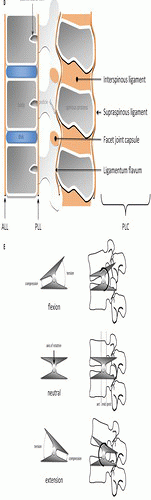
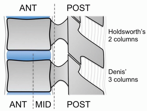
5 In his conception, the vertebra is divided into an anterior and posterior column (
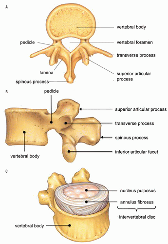
Fig. 7.5). The anterior column consists of the vertebral body, intervertebral disk, anterior longitudinal ligament (ALL), and posterior longitudinal ligament (PLL). The posterior column comprises the facets, neural arch, and posterior ligament complex (interspinous and supraspinous ligaments, facet capsule, and ligamentum flavum). The integrity of the posterior column served as the major determinant of spinal stability. Holdsworth’s classification categorized thoracolumbar spine fractures into anterior compression fractures, fracture dislocations, rotational fracture dislocations, extension injuries, shear injuries, and burst fractures. According to Holdsworth, burst fractures were structurally stable as they were confined to the anterior column. Subsequent e xperimental studies
were unable to produce instability with only PLC disruption. Instability required, in addition to PLC disruption, rupture of the PLL and a portion of the annulus fibrosus.


Figure 7.5. Column concept of the spine. Upper vertebral segment shows Holdsworth’s two columns composed of anterior column (anterior longitudinal ligament, vertebral body, intervertebral disk, posterior longitudinal ligament) and posterior column (posterior bony arch and posterior ligament complex). Lower vertebral segment shows Denis’ three columns comprised of anterior column (ALL, anterior vertebral body, and intervertebral disk), middle column (posterior vertebral body and intervertebral disk, PLL), and posterior column (unchanged from Holdsworth). ALL, anterior longitudinal ligament; PLL, posterior longitudinal ligament.

Based on CT findings and newer experimental instability determinants, Denis modified the Holdsworth two-column model. In 1983, he published a review of 412 thoracolumbar spine injury patients and introduced the concept of the pivotal middle column defined as “the posterior longitudinal ligament, the posterior annulus fibrosus, and the posterior wall of the vertebral body” (Fig. 7.5).6 Consequently, Denis’ anterior column consists of “the anterior longitudinal ligament, the anterior annulus fibrosus, and the anterior part of the vertebral body.” The posterior column, as in Holdsworth’s model, is formed by the posterior bony arch and PLC.

Denis described four major types of spinal injuries along with their mechanisms: compression fractures, burst fractures, seat belt type (flexion distraction), and fracture-dislocations (Table 7.2). Instability, according to the Denis’ three-column model, occurs with failure of two adjacent columns. The middle column represents the key to stability, as it fails either in association with the anterior column, the posterior column, or both. Denis also considered neurologic injury to be a marker of instability and used both mechanical and neurologic features to rate injury severity: first degree for isolated mechanical instability, second degree for isolated neurologic injury, and third degree for combined mechanical and neurologic instability.
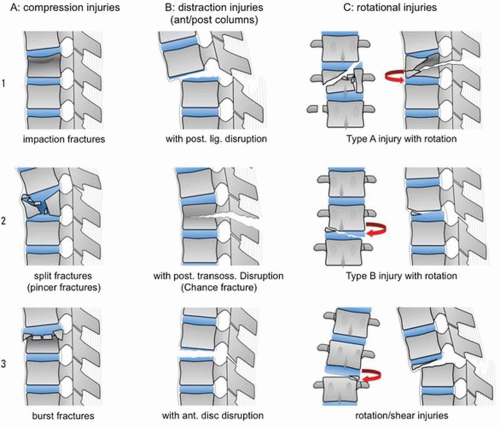
6

The classification proposed by Magerl et al. in 1994 groups all thoracic and lumbar spine fractures into three primary types that have a progressive relationship to one another based on increasing severity of the fracture pattern and degree of soft tissue involvement (Fig. 7.6).7 This classification emphasizes the recognition and importance of ligamentous injury, particularly in the type B and C fractures.

Type A fractures are, in this schema, all the result of axial loading with or without an element of flexion. Type A fractures are limited to the vertebral body with loss of anterior vertebral body height but without posterior ligament complex injury or anterior translation. Type A fractures correspond to simple compression fractures due to hyperflexion.

Type B injuries involve both anterior and posterior columns and are associated with distraction of adjacent vertebrae due to ligamentous injury anteriorly (uncommon, hyperextension) or posteriorly (common, hyperflexion). In typical hyperflexion injuries, the posterior column injury is usually bony as in the Chance fracture or, less commonly, ligamentous as in the “soft tissue” Chance. Anterior translation is common in type B injuries.

Type C injuries include the characteristics of type B with the added element of rotation/shear and are by definition unstable. These injuries most closely correspond to the dislocations or fracture-dislocations of traditional classifications.

Each of these three main fracture types is divided into three groups, which are further divided into three subgroups, and finally into specifications (Table 7.3). Together, the Magerl classification scheme is comprehensive, but also complex, as it catalogues 53 thoracolumbar injury patterns. Injuries are stratified from least severe A1 to most severe C3. No defined criteria for stability are inherent in the Magerl classification. In designing this classification, Denis’ three-column concept is abandoned in favor of Holdsworth’s two columns.


TABLE 7.2 Basic Modes of Failure of Denis’ Three Columns in the Four Major Types of Spinal Injuries


Fracture Type


Column


Anterior


Middle


Posterior


Compression


Compression


None


None


Burst


Compression


Compression


None


Seat-belt type (flexion distraction)


None or compression


Distraction


Distraction


Fracture dislocation


Compression, rotation, shear


Distraction, rotation, shear


Distraction, rotation, shear


From Denis F. The three column spine and its significance in the classification of acute thoracolumbar spinal injuries. Spine. 1983;8(8):817-831, with permission.


Figure 7.6. Magerl spinal classification types and groups. (Modified from Magerl F, Aebi M, Gertzbein SD, et al. A comprehensive classification of thoracic and lumbar injuries. Eur Spine J. 1994;3(4):184-201.)


Stability

Predicting thoracolumbar spine fracture stability from an imaging study is difficult. Stability depends on the integrity of the vertebral bodies, including costal and sternal contributions in the thoracic segment, the ligaments, and joints of the spine. The practical definition of stability by White and Panjabi states that a stable spine is able to withstand physiologic loads without producing mechanical deformity or progressive neurologic injury or pain.8 From both clinical and radiologic perspective, the three-column concept of Denis is most widely applied for determining thoracolumbar spine stability. According to Denis, failure of two or three columns yields instability, with disruption of the middle column representing the key contributing factor.

To simplify the imaging approach to stability, six radiologic signs of spinal instability
have been described: (1) displacement, (2) wide interspinous space, (3) abnormal facet joints, (4) posterior vertebral body line disruption, (5) wide interpediculate distance, and (6) wide intervertebral disk space (Table 7.4). The presence of any one of these features indicates major injury to the supporting bone, ligaments, or joints and is felt to be sufficient to diagnose instability. Although originally described for radiographs, these features are applicable to, and in many cases, better seen with CT.

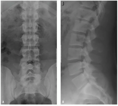
The common major fracture patterns described by Denis are compression, burst, flexion distraction (or Chance-type fractures), and fracture dislocations.


TABLE 7.3 Classification Scheme According to Magerl


Only gold members can continue reading. Log In or Register to continue

Stay updated, free articles. Join our Telegram channel

Jun 20, 2016 | Posted by in GENERAL RADIOLOGY | Comments Off on Imaging Thoracolumbar Spine Trauma

Full access? Get Clinical Tree

Get Clinical Tree app for offline access

Type A Injuries: Groups, Subgroups, and Specifications


Type A. Vertebral body compression


A1.


Impaction fractures


A1.1.


End plate impaction


A1.2.


Wedge impaction fractures


1


Superior wedge impaction fracture


2


Lateral wedge impaction fracture


3


Inferior wedge impaction fracture


A1.3.


Vertebral body collapse


A2.


Split fractures


A2.1.


Sagittal split fracture


A2.2.


Coronal split fracture


A2.3.


Pincer fracture


A3.


Burst fractures


A3.1.


Incomplete burst fracture


1


Superior incomplete burst fracture


2


Lateral incomplete burst fracture


3


Inferior incomplete burst fracture


A3.2.


Burst-split fracture


1


Superior burst-split fracture


2


Lateral burst-split fracture


3


Inferior burst-split fracture


A3.3.


Complete burst fracture


1


Pincer burst fracture


2


Complete flexion burst fracture


3


Complete axial burst fracture


Type B Injuries: Groups, Subgroups, and Specifications


Type B. Anterior and posterior element injury with distraction


B1.


Posterior disruption predominantly ligamentous (flexion-distraction injury)


B1.1.


With transverse disruption of the disc


1


Flexion-subluxation


2


Anterior dislocation


3


Flexion-subluxation/anterior dislocation with fracture of the articular processes


B1.2.


With Type A fracture of the vertebral body


1


Flexion-subluxation + Type A fracture


2


Anterior dislocation + Type A fracture


3


Flexion-subluxation/anterior dislocation with fracture of the articular processes + Type A fracture


B2.


Posterior disruption predominantly osseous (flexion-distraction injury)


B2.1.


Transverse bicolumn fracture


B2.2.


With transverse disruption of the disc


1


Disruption through the pedicle and disc


2


Disruption through the pars interarticularis and disc (flexion-spondylolysis)


B2.3.