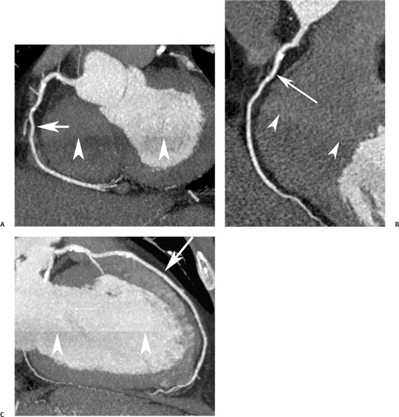
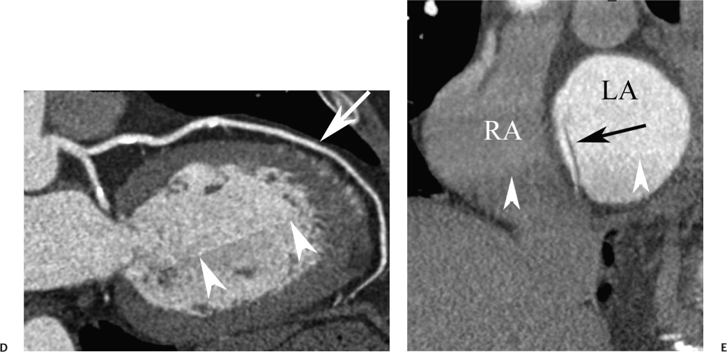
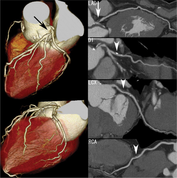
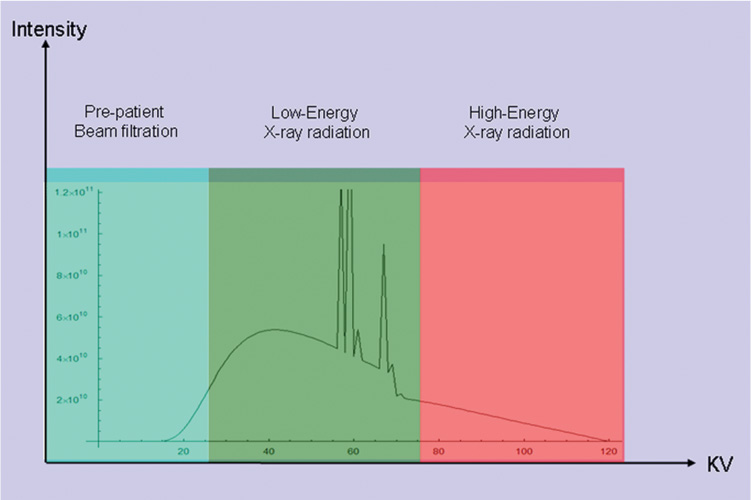
16 The field of cardiac imaging has advanced rapidly over the past few decades. The latest innovations in technology provide better image quality with noninvasive techniques using lower doses of radiation compared with techniques used in the recent past. Innovations from the past two decades provide the basis for most of this text. New innovations in the coming years will expand further the clinical applications of cardiac CT to provide a comprehensive anatomic and functional examination of the heart. This chapter reviews several key innovations in CT technology as they are applied to cardiac imaging. To increase z-axis coverage, new scanners have been developed with larger detector panels that can image the entire heart at once. Extended z-axis of up to 16 cm of coverage has several potential advantages for cardiac imaging. Because the entire heart can be imaged at one time, coronary CT angiography (CTA) may be obtained in a single heartbeat, thus minimizing the impact of an arrhythmia on scan quality as well as reducing radiation. With sufficient temporal resolution, coronary CTA with extended z-axis coverage might be possible without electrocardiographic (ECG) gating. Because the entire scan can be acquired with a single axial scan using prospective ECG triggering, extended z-axis detectors should eliminate additional radiation exposure related to the overlap between the sequential axial acquisitions that would be required when using a scanner with a shorter z-axis coverage. Furthermore, simultaneous imaging of the entire heart during the same arterial phase of contrast arrival should facilitate more accurate perfusion CT imaging of the myocardium. Scanners with 128 rows of detectors and a z-axis wobble that acquires 256 slices are commercially available. These scanners have a detector element that is 8 cm in the z-axis and can acquire a complete coronary CTA in two steps with prospective ECG gating (Fig. 16.1). Although the detector element is 8 cm long, the actual coverage in two steps is reduced by 2 to 3 cm (less than the 16-cm coverage that might be expected) because of the overlap required by the cone beam reconstruction algorithm. A recent study estimated an effective dose of 3.2 mSv for prospective ECG gating with a 256-slice scanner with 80-mm detector coverage.1 A phantom model study suggests that scanners with 256 detector rows may provide cardiac imaging during a single heartbeat without ECG gating, thereby eliminating artifacts related to ectopy and variability of heart rate.2 This nongated approach has yet to be validated in an in vivo clinical trial. One vendor has introduced a 320-detector row scanner (16cm detector) capable of imaging the entire coronary circulation in a single axial acquisition (Fig. 16.2).3 Coronary imaging with this scanner has been described as providing excellent diagnostic quality with axial scanning using both ECG-gated and nongated modes.4 The ability to perform coronary CTA during a single cardiac cycle should result in more reliable imaging of the coronary circulation in patients with cardiac arrhythmias. Furthermore, the injected contrast volume can be minimized as long as the injection is optimized to ensure optimal opacification of the entire coronary tree during the single cardiac cycle used for imaging. CT evaluation of small coronary arteries and stents is currently limited by scan resolution. Although conventional coronary angiography has a resolution of about 0.2 mm, the detector elements in multislice CT provide a z-axis slice thickness of no less than 0.5 to 0.75 mm. In-plane resolution for conventional scanners is limited by the scanner sampling rate (number of samples per rotation) and by pixel size, which is typically on the order of 0.5 mm (using a 250-mm field of view with a 500 × 500 pixel image). Coronary vessels are 3 to 4 mm wide, corresponding to six to eight pixels in current technology. Thus, a difference in stenosis of between 60 and 80% may correspond to a difference of only a single pixel. Vendors have increased the in-plane resolution on commercial systems based on multislice detectors by increasing sampling rates per gantry rotation for newer systems. This sampling rate may be limited by the afterglow time of detector material or by the speed of the electronics that must transmit the data from the detector to the processing computer. Flat-panel detector technology currently under development has the potential to provide superior resolution in all planes compared with current multiple-row detector technology. In vivo implementation of this flat-plate technology, however, is limited by the extremely rapid sampling rates that are required for flat plate technology. A prototype flat-panel unit that has been used to image explanted human heart specimens provides an isotropic voxel with 0.25-mm resolution.5 Another study using flat-panel technology imaged an excised pig heart with visualization of coronary arteries down to fifth-degree branches.6 The superior resolution of flat-panel technology can minimize blooming artifact associated with vascular calcifications and stents, thereby providing improved visualization of the vessel lumen.7 A recent study demonstrated the application of flat-panel imaging to the coronary arteries in 25 isolated hearts removed during autopsy.8 This study suggests that flat-panel volume CTA may have sufficient resolution to detect reliably the lipid pool within coronary plaque. Temporal resolution of these prototype systems, as well as image artifacts, currently limits their clinical application, but these are likely to improve in the near future. Fig. 16.1 Coronary CT angiography (CTA) acquisition in two steps with prospective electrocardiographic (ECG) gating. The step artifact is most visible on images that are rendered in a plane perpendicular to the z-axis. (A) Slab maximum intensity projection (MIP) left anterior oblique projection of the right coronary artery (RCA) (arrow). The demarcation between the two steps is visible (arrowheads) but does not interfere with interpretation as long as the vessel is well aligned in the two steps. (B) Curved multiplanar reformat (MPR) of the RCA (arrow) based on vessel tracking. The demarcation between the two steps is present but not as visible (arrowheads). (C) Slab MIP right anterior oblique projection of the left anterior descending artery (LAD) (arrow). The demarcation between the two steps is again visible (arrowheads), but this does not interfere with evaluation of the LAD. (D) Curved MPR of the LAD (arrow) based on vessel tracking. The demarcation between the two steps is only visible within the left ventricular cavity (arrowheads) and is less obvious than in part C. (E) Oblique sagittal view through the right atrium (RA) and left atrium (LA) in the same patient demonstrates that the septum primum (arrow) is not fused to the septum secundum, resulting in a patent foramen ovale. The step artifact (arrowheads) is present but less well defined in parts (B), (D), and (E) because the image is rendered in a plane that is oblique to the step artifact. A smoothing filter can be used to remove this “step artifact,” but the edges of the coronary arteries may not be as sharply defined in the smoothed image. Various tissues demonstrate differences in radiographic attenuation based on a range of Compton and photoelectric effects at different energies. Multienergy techniques exploit these differences to provide improved image quality or additional tissue characterization.9 Although dual-energy CT applications were described more than 30 years ago,10 advances in technology have only recently made these applications a reality for cardiac imaging. Dual-energy CT refers to the synchronous acquisition of CT data at two different ranges within the spectrum of roentgen tube energies (Fig. 16.3). Perhaps the most important application of dual-energy imaging is for the improved visualization of iodine. The radiographic attenuation of iodine is much greater at 80 kVp compared with 140 kVp, but the relative change in radiographic attenuation as a function of kVp is different for iodine compared with water or calcium. Based on these differences in relative attenuation at low and high kVp, dual-energy data may be mathematically processed with material decomposition algorithms that enhance or suppress iodine relative to water or tissue or iodine relative to bone (Fig. 16.4).11–13 Material decomposition may be used to identify tissues that would be very difficult to distinguish on conventional single-energy scan (Fig. 16.5). As an extension of this process, dual-energy post-processing may be used to provide “iodine maps” and quantitative estimates of iodine concentration in tissue (Fig. 16.6). Further processing of dual-energy CT images may be performed to provide “monoenergetic” images that are created to simulate the image that would be obtained using a single keV radiographic source. Such monochromatic images may be useful to eliminate artifacts related to beam hardening. Several options for acquiring dual-energy CT data for cardiac imaging have been implemented. The first commercially available dual-energy system was based on a dual-source CT scanner with two different roentgen tubes and two sets of detectors. Although the dual-source design was initially implemented to improve temporal resolution at a single kVp, the two roentgen tubes may be operated at different kVp settings to obtain dual-energy information. An interesting advantage of this approach is the ability to process information selectively from either one or both radiographic sources to optimize temporal resolution versus energy-specific information (see below for application to myocardial perfusion imaging). A disadvantage of this approach is the slight difference in the time of acquisition for two co-registered data sets based on the additional quarter revolution of the gantry between the two sources. The lack of precise co-registration limits this vendor’s ability to combine dual-energy raw data in “projection space” during the reconstruction phase of CT processing. Dual-energy data may still be combined in “image space” by post-processing of the images obtained from the two radiographic sources to perform material decomposition and to provide monochromatic images.14 Clinical studies are needed to determine the relative advantages of dual-energy reconstructions in raw data projection space versus image space. Fig. 16.2 Single heartbeat acquisition of the entire coronary circulation. The two panels on the left demonstrate volumetric renderings of the coronary circulation with the underlying cardiac chambers. A focal stenosis is present in the proximal left anterior descending artery (black arrow). The four right-sided panels demonstrate curved maximum intensity projection renderings of the left anterior descending artery (LAD), first diagonal branch (D1), left circumflex artery (LCX), and right coronary artery (RCA). Moderate to severe narrowing in the proximal LAD is clearly defined (arrow), as is the presence of calcified plaque in D1 (arrowhead) and noncalcified plaque in the LCX and RCA (arrowheads). Note that there is no “step artifact” in this one-step acquisition. Acquisition of the entire scan within a single cardiac cycle limits the negative impact of cardiac arrhythmia. (Figure supplied courtesy of Toshiba Medical Systems, Japan.) Fig. 16.3 Spectrum of radiographic energies received by a CT detector. Although a single kVp is applied across the roentgen tube to generate the roentgens for the scan, the polychromatic beam contains a spectrum of energies. Pre-patient beam filtration is used to remove low-energy photons that would contribute little information to a scan but increases patient’s radiation exposure. Multienergy techniques measure the selective absorption of the radiographic beam in different portions of the spectrum. Dual-energy techniques divide the spectrum into high- and low-energy components.
Innovations in Cardiac CT: Slice Wars, Dual Energy, Myocardial Perfusion, and Targeted Contrast Agents
 More Slices, More Resolution, and Flat-Panel CT
 Dual-Energy and Spectral CT
Related posts:
Stay updated, free articles. Join our Telegram channel

Full access? Get Clinical Tree


