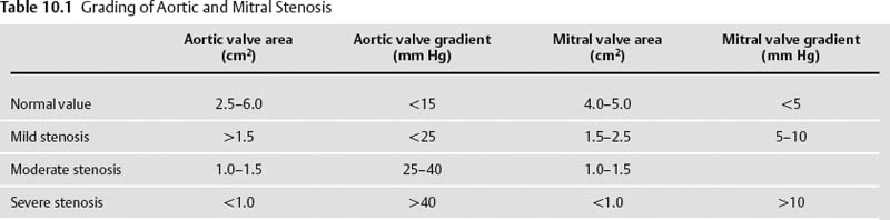
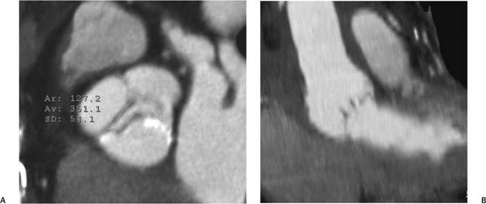
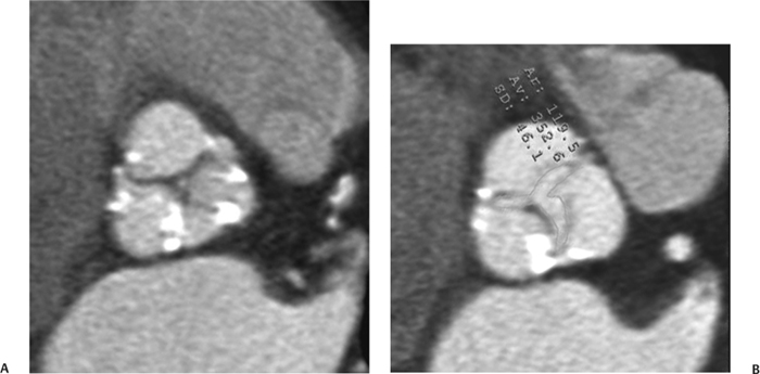
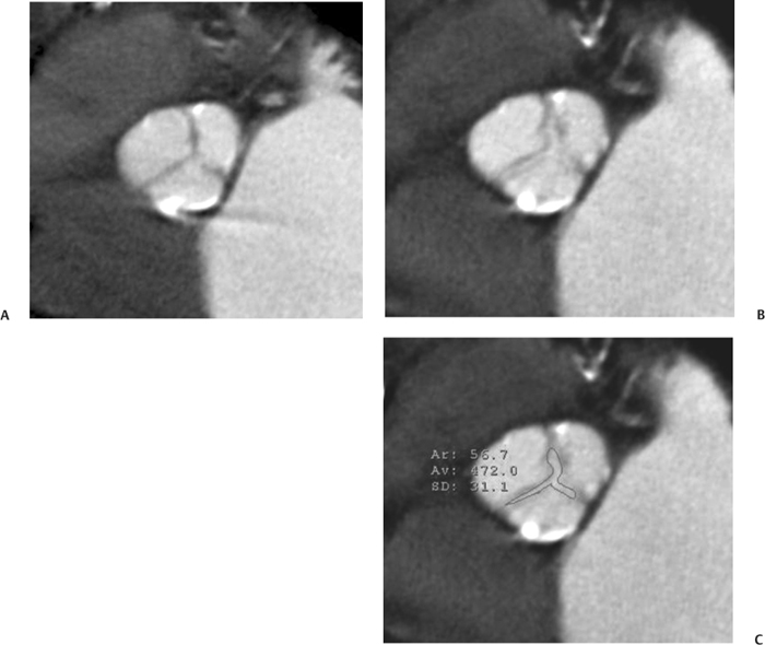
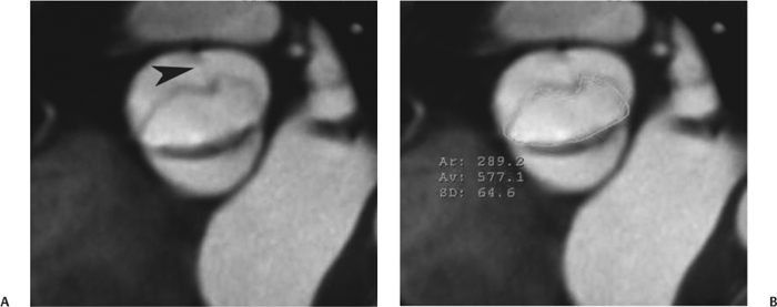
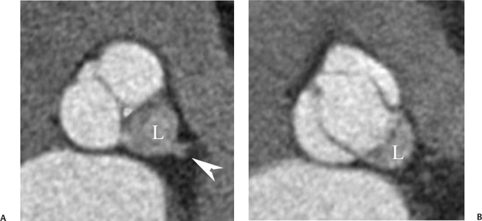
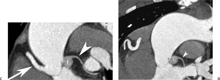
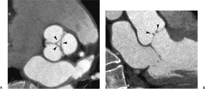
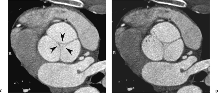
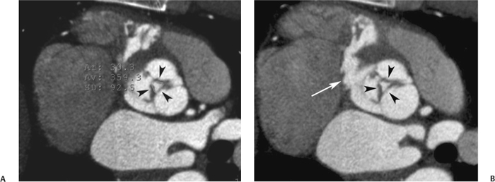
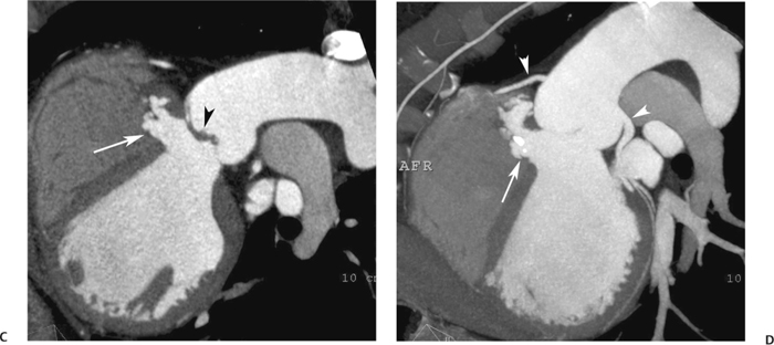
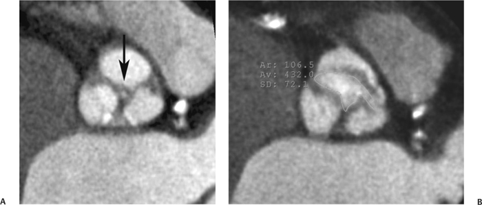
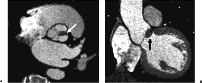
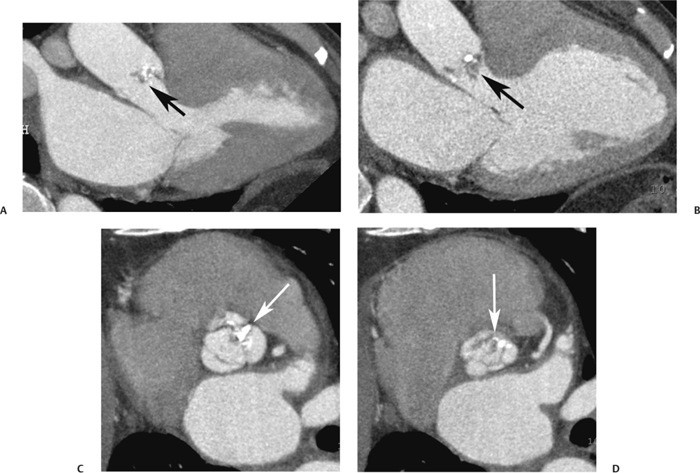
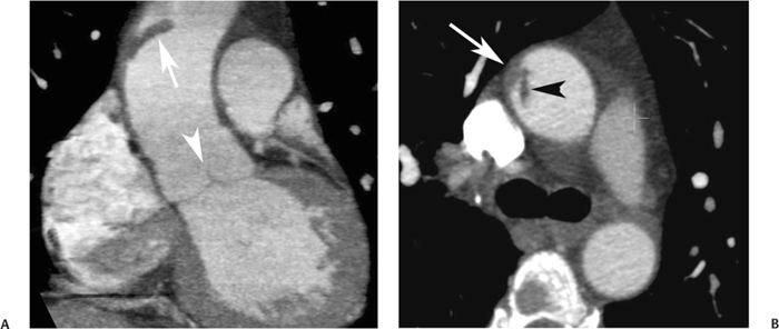
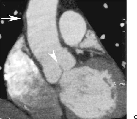
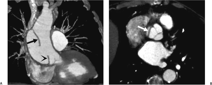
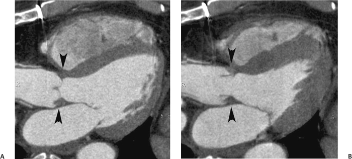
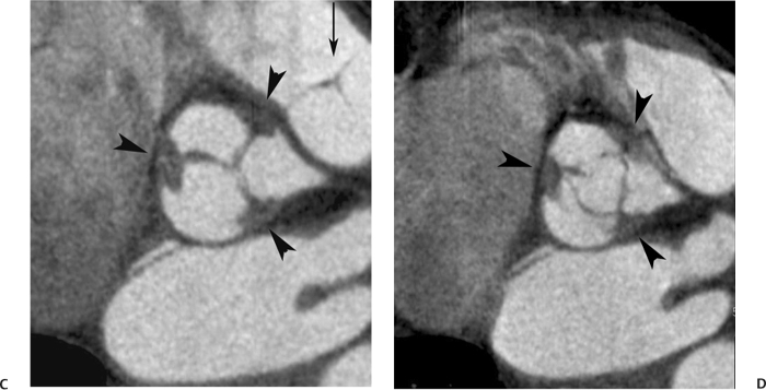
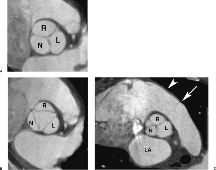
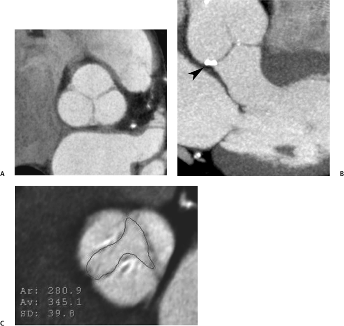
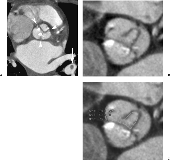
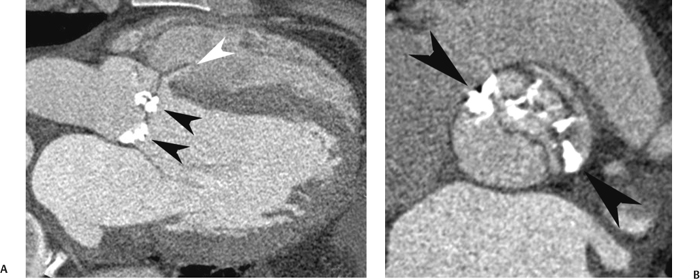
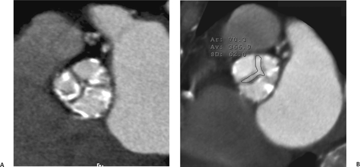
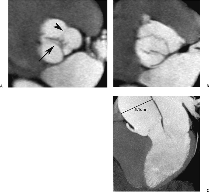
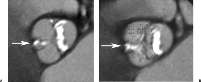
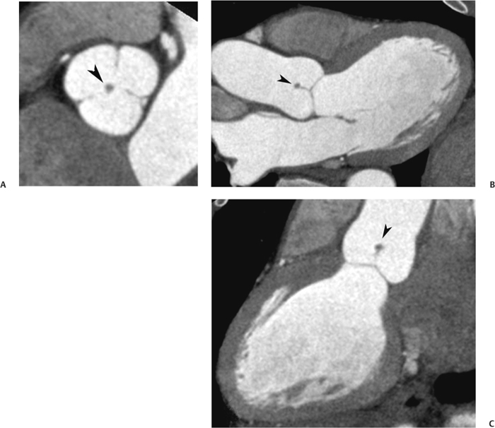
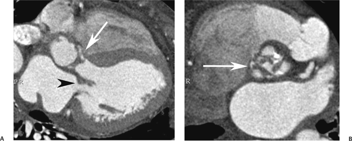
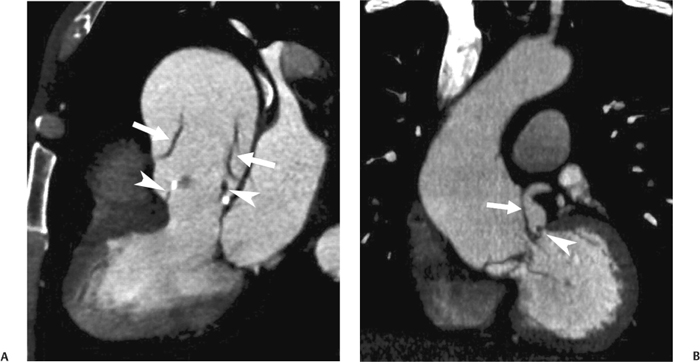
10 Assessment of the cardiac valves is an integral part of a comprehensive cardiac CT assessment. Valve dysfunction may be related to coronary disease and can be the cause or the consequence of alterations in cardiac morphology and function. The aortic and mitral valves are well visualized with coronary CT angiography (CTA) because there is ample contrast in the left heart. CTA often provides complementary information to echocardiography for the evaluation of normal and diseased valves.1 When the examination is performed with an appropriate infusion of contrast material to assess right-sided cardiac structures, the pulmonic and tricuspid valves may also be evaluated. Most recently, CTA has been applied to planning and post-procedure evaluation of transcatheter valve implantation.2,3 The aortic valve consists of three leaflets of equal size attached along the aortic annulus at the proximal margin of the aortic root (Fig. 10.1). In the closed, diastolic position, the three commissures that separate the leaflets intersect at the center of the annulus at 120-degree angles. During systole the valve leaflets swing superiorly into the sinuses of Valsalva, revealing the triangular orifice of the aortic valve. Normal aortic valve motion is documented by demonstration of complete coaptation of the leaflets in diastole and unrestricted leaflet motion in systole to form an equilateral triangle whose vertices extend to the walls of the aortic root. The annulus of the aortic valve is located between the left ventricular outflow tract (LVOT) and the aortic root. A short-axis image through the aortic annulus demonstrates that the annulus and aortic valve are related to the pulmonic valve, which is located anterior and to the left of the aortic valve. The commissure between the right and left cusps of the aortic valve is aligned with the posterior commissure of the pulmonic valve (see discussion of aortic root in Chapter 3). The posterior aspect of the aortic annulus is in direct fibrous continuity with the anterior wall of the left atrium and the anterior mitral leaflet, as demonstrated on the long-axis view of the heart (Fig. 10.2). The aortic valve is imaged with little motion artifact because the leaflets remain in a fixed, closed position throughout diastole and in a relatively stable open position throughout most of systole. The open aortic valve is best visualized during mid-systole, at about 20 to 30% of the RR interval. The closed aortic valve is best visualized in middiastole, at about 70 to 80% of the RR interval. The precise phase at which the valve is best imaged depends on the patient’s heart rate and may be vendor specific, depending on the method used to define percentage of the RR interval. The individual aortic valve cusps are best imaged in the short axis (Fig. 10.2A), whereas valve motion is best visualized in the long axis (Fig. 10.2B). Echocardiography is the noninvasive standard for assessment of aortic valve function. Aortic valve morphology and function are evaluated echocardiographically in both the short and long axis. Aortic valve area is estimated with a hemodynamic calculation based on the continuity equation4 or by direct planimetry.5 Assessment of the aortic valve with CT is based on evaluation of the aortic leaflet morphology, aortic leaflet motion, and direct planimetry. Hemodynamic measurements are not possible with CT. Several studies suggest that planimetric measurements of the narrowest aortic valve orifice observed in midsystole demonstrate high correlation with aortic valve area calculated with the continuity equation using transesophageal echocardiography.6–8 Our own experience suggests that planimetric measurements on CT are slightly larger than aortic valve area calculated from the continuity equation with echocardiography. The lower estimates of aortic valve area by echocardiography are likely related to the elliptical shape of the LVOT (see Fig. 9.2), which results in echocardiographic underestimation of the LVOT area.9 The most common causes for aortic stenosis in adults include degenerative calcification of a normal trileaflet valve, rheumatic aortic valvulitis, and congenital bicuspid valve. Calcific aortic stenosis is a process characterized by accumulation of calcium that resembles ectopic bone formation. This process may share a pathophysiologic pathway with atherosclerosis of the coronary arteries.10 Renal dysfunction and abnormal calcium metabolism may accelerate aortic valve calcification. Calcific aortic sclerosis is present in about 25% of adults over the age of 65 and is associated with a 50% increased risk of myocardial infarction and cardiovascular death compared with age-matched controls with a normal aortic valve.11,12 Rheumatic heart disease was once a common cause of aortic stenosis but is now much less common and almost invariably accompanied by mitral valve disease. Other less common causes of aortic stenosis include homozygous hypercholesterolemia and systemic lupus. Fig. 10.1 (A) Short-axis view of the aortic valve during diastole. The three cusps of the aortic valve are defined by the commissures that separate the right (R), left (L), and noncoronary (N) cusps. (B) Short-axis image of the tricuspid aortic valve during systole demonstrates a triangular opening as the three cusps separate along their commissures. The right ventricular out-flow tract crosses anterior to the aorta at the level of the aortic valve. (C) Using a slightly different angulation, the right ventricular outflow tract is demonstrated (arrowhead) with the pulmonic valve (arrow). The left atrium (LA) is posterior to the aortic valve. Because the area of aortic valve varies with patient body habitus, a fixed lower threshold value for aortic valve area cannot be provided. Several studies suggest that the valve area measured by CT planimetry correlates well with echocardiographic measurements in aortic stenosis.13 In our experience using direct planimetry of the aortic valve with CTA, the mean normal adult aortic valve area is 4.2 cm2 with a range from about 2.5 to 6 cm2.14 The 2006 American College of Cardiology (ACC)/American Heart Association (AHA) guidelines for normal aortic and mitral valve areas are summarized in Table 10.1.15 Mild aortic stenosis demonstrates a valve area greater than 1.5 cm2 with a mean gradient less than 25 mm Hg. When the valve motion appears restricted but the CT planimetric measurement is greater than 1.5 cm2, the stenosis is classified as mild (Fig. 10.2C). A valve area of about 1.5 cm2 is classified as mild to moderate stenosis (Fig. 10.3). Moderate aortic stenosis demonstrates a valve area in the range of 1.0 to 1.5 cm2 with a mean gradient in the range of 25 to 40 mm Hg (Figs. 10.4, 10.5, and 10.6). Severe aortic stenosis demonstrates a valve area of less than 1 cm2 with a mean gradient greater than 40 mm Hg (Fig. 10.7). When the aortic valve area is less than 0.7 cm2, aortic stenosis is classified as critical (Fig. 10.8). As noted, our experience suggests that aortic valve area measured at coronary CTA is slightly larger than the area suggested by echocardiography.9 Because the ACC/AHA guidelines are based on echocardio-graphic measurements, allowances should be made for a slightly greater area on CTA. Fig. 10.2 Calcified aortic valve without significant stenosis. (A) Short-axis image of the aortic valve demonstrates normally placed commissures of a trileaflet valve. (B) Three-chamber view through the aortic valve demonstrates the presence of calcification at the margin of the valve leaflets (arrowhead). (C) Short-axis image through the valve in systole demonstrates a trileaflet opening with valve area of 2.8 cm2 by planimetry, suggesting that there is only minimal restriction of valve motion. Although the classification of aortic stenosis is based on valve area, absolute valve area might not correlate with symptoms. Valve area indexed to body surface area may provide a better estimate of the true severity of stenosis, and clinical management of patients with aortic stenosis must be based on the patient’s symptoms. As a general rule, however, the rate of progression of aortic stenosis and clinical outcome can be predicted based on hemodynamic factors and the aortic valve area.16 Bicuspid aortic valve is easily diagnosed by cardiac CTA. The bicuspid valve demonstrates a characteristic “fish-mouth” opening, which is distinct from the normal triangular opening of the trileaflet aortic valve. A bicuspid valve may demonstrate a fused commissure, known as a pseudoraphae, or absence of an expected commissure (Figs. 10.9 and 10.10). CT grading of stenosis for a bicuspid valve is based on planimetry (Figs. 10.10 and 10.11). When performing planimetry of a bicuspid aortic valve, particular care is required to measure the narrowest orifice observed in midsystole. Patients with bicuspid aortic valve often have a disorder of vascular connective tissue that can result in aortic root dilatation, even in the absence of a hemodynamically significant stenosis of the aortic valve.17–19 The recommended threshold for elective replacement of a dilated ascending aorta is lower in patients with bicuspid aortic valve because of an increased risk of dissection or rupture. When a biscuspid valve demonstrates normal function, elective replacement is recommended when the diameter of the aorta exceeds 5 cm (Fig. 10.9). In a patient with a bicuspid valve that must be replaced, replacement of the ascending aorta is recommended when the diameter is greater than 4.5 cm.20 Aortic root and ascending aorta replacement is also suggested when the rate of increase in diameter is greater than 0.5 cm per year. Fig. 10.3 Aortic stenosis and pulmonary embolism in a patient presenting with syncope. (A) Short-axis image during diastole demonstrates a calcified trileaflet aortic valve (arrowheads), as well as an acute pulmonary embolus (arrow). (B) Short-axis image of the valve during systole demonstrates mild to moderate restriction of leaflet opening. (C) Planimetry measurements demonstrate a valve area of 1.5 cm2, correlating with the diagnosis of mild to moderate aortic stenosis. Fig. 10.4 Calcified aortic valve with moderate stenosis. (A) Short-axis image during systole demonstrates restricted opening of the valve with a valve area of 1.3 cm2 by planimetry. (B) Long-axis view during systole confirms restriction of leaflet motion. Fig. 10.5 Calcified aortic valve with moderate stenosis and subvalvular perimembranous ventricular septal defect (VSD). (A) Three-chamber image during diastole demonstrates the calcified aortic valve (black arrowheads) as well as an anterior subvalvular VSD (white arrowhead). (B) Short-axis image during systole demonstrates restricted opening of the calcified valve with a valve area of 1.3–1.4 cm2, suggesting moderate aortic stenosis. Fig. 10.6 Calcified aortic valve with moderate stenosis and mild insufficiency. (A) Short-axis image during diastole demonstrates incomplete coaptation at the center of the valve, consistent with the diagnosis of aortic insufficiency. (B) Short-axis image during systole demonstrates restricted opening of the calcified valve with a valve area of 1.2 cm2 by planimetry. Fig. 10.7 Calcified aortic valve with severe stenosis. (A) Short-axis image during diastole demonstrates diffuse calcification of the aortic valve, as well as thickening of the commissures and a small regurgitant orifice at the center of the valve. (B) Short-axis image of the valve during systole demonstrates severe stenosis with a valve area of 0.7 cm2. Fig. 10.8 Critical aortic stenosis. (A) Short-axis image through the aortic valve demonstrates minimally thickened commissures of a trileaflet valve with calcification around the aortic annulus. (B) Short-axis image through the aortic valve during systole demonstrates severe restriction of motion in this trileaflet valve. (C) Valve area of 0.56 cm2 by planimetry is compatible with critical aortic stenosis. Fig. 10.9 Bicuspid aortic valve with an ascending aortic aneurysm. (A) Short-axis through the aortic valve in diastole demonstrates a thickened commissure (arrow) separating the noncoronary cusp from the remainder of the valve. There is also a thin commissure (a rrowhead) separating the right and left coronary cusps. (B) Short-axis image during systole demonstrates a bicuspid valve. The left and right coronary cusps function as a single leaflet. The apparent commissure between these cusps is a pseudoraphae. The classic fishmouth-shaped opening of the aortic valve is diagnostic of a bicuspid valve. (C) This patient also has an aneurysm of the ascending aorta. Bicuspid aortic valve may be associated with congenital abnormalities of collagen synthesis and increased risk of aneurysm rupture. This patient was taken to surgery for replacement of the aortic valve, as well as the ascending aortic aneurysm. Fig. 10.10 Bicuspid aortic valve. (A) Short-axis image of the aortic valve during systole demonstrates the classic fishmouth-shaped opening of a bicuspid valve with a pseudoraphae between the right and left coronary cusps (arrowhead). (B) Planimetry of the bicuspid valve demonstrates a valve area of 2.9 cm2, suggesting that there is no significant stenosis. Fig. 10.11 Bicuspid aortic valve with moderate to severe stenosis. (A) Short-axis image of the aortic valve during diastole demonstrates calcified commissures. (B) Short-axis image during systole demonstrates fusion of the commissure between the right coronary and non-coronary cusps (arrow). The aortic valve area by planimetry measures 1.1 cm2, compatible with moderate to severe aortic stenosis. In a rare variation, a trileaflet aortic valve may present as a functionally bicuspid valve secondary to fusion of an aortic valve leaflet to the wall of the aorta. Fusion of the free margin of an aortic valve leaflet to the aortic wall at the sinotubular junction likely represents failure of normal embryologic cavitation of endocardial cushion tissue in the LVOT.21 We recently encountered a case of a trileaflet aortic valve with the left coronary cusp congenitally fixed in an open position and blocking the flow of blood into the left sinus of Valsalva (Fig. 10.12). Although there are three independent leaflets, only two of the leaflets demonstrated normal motion, resulting in a functionally bicuspid valve. In our patient, this anomaly was associated with aortic insufficiency as well as an aneurysm of the ascending aorta. Fig. 10.12 Rare aortic valve anomaly resulting in a functionally bicuspid valve with an associated aneurysm of the ascending aorta. (A) Short-axis view of the aortic valve in diastole demonstrates a lack of contrast opacification in the left sinus of Valsalva (L), associated with lack of contrast in the origin of the left coronary artery (arrowhead). A small central regurgitant orifice is present. (B) Systolic view demonstrates that two of the aortic cusps open normally. The triangular appearance of the open aortic valve clearly demonstrates the presence of three aortic leaflets. However, the left coronary cusp remains unchanged in position, fixed over the left sinus of Valsalva. Rare aortic valve anomaly resulting in a functionally bicuspid valve with an associated aneurysm of the ascending aorta. (C) Coronal view of the aortic root during diastole. There is a lack of opacification of the left sinus of Valsalva (L) and the left coronary artery (arrowhead). A large right coronary artery (arrow) supplies the left system via collaterals. (D) Oblique view of the ascending aorta demonstrates the presence of an aneurysm that measured greater than 4 cm. Again noted is the lack of opacification of the left sinus of Valsalva (L) and the left coronary artery (arrowhead). The diagnosis and grading of aortic regurgitation are usually performed by echocardiography. Diameter of the regurgitant jet, vena contracta measurement, pressure half-time measurement, and hemodynamic calculations may be used for echocardiographic grading of the severity of aortic regurgitation. Cardiac CTA can demonstrate incomplete coaptation of the aortic valve in diastole and can be used to measure the regurgitant orifice (Fig. 10.13) but cannot provide hemodynamic data to assess the severity of aortic insufficiency. Although CT is sensitive for the presence of moderate to severe aortic insufficiency, CT is relatively less sensitive for the presence of mild aortic insufficiency, especially in the setting of a calcified or bicuspid valve.22 Enlargement of left ventricular chamber size accompanies chronic severe aortic regurgitation and suggests that the regurgitant lesion is hemodynamically significant. Measurements of left ventricular volume in systole and diastole are useful when deciding on surgical intervention for aortic regurgitation. Common causes for aortic regurgitation include primary abnormalities of the aortic valve (bicuspid valve, myxomatous degeneration) or dilatation of the aortic root (hypertension, connective tissue disorders). Hypertension is the most common cause of aortic dilatation, followed by congenital abnormalities of collagen synthesis. Dilatation of the aortic root leads to displacement of the commissural attachments of the valve leaflets with resultant malcoaptation. Less common causes of aortic regurgitation include endocarditis and aortic dissection (see discussion later in this chapter). Fig. 10.13 Two cases of mild aortic insufficiency. (A) Short-axis view through the aortic valve in diastole demonstrates mildly thickened commissures, with incomplete coaptation at the center of the valve (arrowheads). (B) Three-chamber view through the aortic valve again demonstrates thickened aortic leaflets with incomplete coaptation (arrowheads). Incomplete coaptation is associated with a central regurgitant jet through the aortic valve. (C) Short-axis view through the aortic valve in another patient demonstrates incomplete coaptation at the center of an otherwise normal valve (arrowheads). (D) Planimetry demonstrates a regurgitant orifice of 0.18 cm2, compatible with the history of mild aortic insufficiency. Incomplete coaptation of the aortic valve may be demonstrated in both short axis and long axis during diastole (Figs. 10.12 and 10.13). Aortic insufficiency may be associated with abnormalities of the adjacent cardiac structures, such as the membranous ventricular septum (Fig. 10.14). Finally, aortic insufficiency may be present concomitantly with aortic stenosis when thickening of the valve leaflets restricts opening and also prevents adequate coaptation (Fig. 10.15). Aortic valve leaflets are sharply defined on cardiac CT as three discrete structures. Small, soft tissue tags along the aortic leaflets, ranging in length from 0.3 to 0.6 mm, are described on pathologic studies. These Lambl’s excrescences have been reported in 70 to 90% of valves during autopsy, but they are not visible with current cardiac CT technology. Another normal pathology finding, the nodules of Arantius, is small collections of fibrous tissue located near the free edges of the aortic cusps. These anatomic variations are not visible on CT, although in theory they could mimic the presence of a small tumor. Fig. 10.14 Thickened aortic valve with mild aortic insufficiency and an associated ventral septal defect (VSD) in the aortic outflow tract. (A) Short-axis image through the aortic valve in diastole demonstrates thickened commissures with incomplete coaptation (arrowheads). The regurgitant valve orifice is measured at 0.3 cm2. (B) Short-axis image with a slightly modified angulation demonstrates a VSD that is immediately below the aortic valve (arrow). The VSD may contribute to abnormal flow patterns around the aortic valve and lead to early degeneration of the valve leaflets. Thickened aortic valve with mild aortic insufficiency and an associated ventral septal defect (VSD) in the aortic outflow tract. (C) Coronal view of the aortic root demonstrates the thickened aortic valve (arrowhead), with a high VSD present immediately below the valve. (D) Left anterior oblique view demonstrates the relationship of the coronary arteries (arrowheads), to the aortic valve and the VSD (arrow). Cardiac CTA may be used to demonstrate a variety of valvular abnormalities.23 The most common primary tumor of the aortic valve is the fibroelastoma, which generally appears as a small ball on a stalk, with frond-like protrusions. These can occur on either side of the valve, but are more commonly found on the aortic surface or affixed to the commissural attachments of the valve (Fig. 10.16). Despite the benign histologic appearance, aortic fibroelastomas may embolize and result in stroke. They are most commonly diagnosed by transesophageal echocardiography. Noninfectious vegetations of the heart valves in a setting of systemic lupus erythematosus were first described by Libman and Sacks in 1924.24 These verrucous projections usually occur on the ventricular surface of the valve, along the valve ring or commissures (Fig. 10.17). In autopsy studies of lupus patients, the prevalence of Libman–Sacks vegetations ranges from 13 to 74%.25 Similar lesions are described in the anti-phospholipid antibody syndromes.26 These noninfectious vegetations have been shown to frequently change over time on serial echocardiograms.27 There is debate whether the incidence of these lesions has decreased in the era of increased steroid use. There is no clear association with other markers of disease activity, but these are thought to represent valvulitis. Diffuse valvular thickening commonly occurs in systemic lupus erythematosus, and extensive valvular thickening is associated with progressive valvular deterioration requiring valve replacement.25 Fig. 10.15 Thickened aortic valve with mild regurgitation and moderate to severe stenosis. (A) Short-axis image of the aortic valve in diastole demonstrates thickened commissures as well as incomplete coaptation at the center of the valve (arrow). (B) Short-axis image through the aortic valve in systole again demonstrates the thickened valve leaflets. There is a triangular opening with restriction of leaflet motion. Plani-metric measurement of 1.06 cm2 is compatible with moderate to severe aortic stenosis. Fig. 10.16 Fibroelastoma of the aortic valve. (A) Short-axis image of the aortic valve in diastole demonstrates a normal trileaflet valve. At the center of the valve there is a small focal hypodensity (arrowhead). (B) Three-chamber view of the left ventricle in diastole demonstrates a closed aortic valve with normal coaptation of the leaflets. A rounded hypodensity extends just above the aortic valve on a small stalk (arrowhead). (C) Coronal view of the left ventricle and ascending aorta again demonstrates a small hypodensity that extends from the aortic valve on a thin stalk (arrowhead). A small fibroelastoma was removed from the tip of the aortic valve at surgery. Fig. 10.17 Libman–Sacks endocarditis in a patient with systemic lupus erythematosus and peripheral arterial emboli. (A) Short-axis through the aortic valve demonstrates a soft tissue mass along the commissure between the left and right coronary cusps. (B) Coronal image through the aortic valve confirms this well-defined soft tissue vegetation. At surgery the vegetation was consistent with Libman–Sacks endocarditis. (Reprinted with permission from Gilkeson RC, Markowitz AH, Balude A, Sachs PB. MDCT evaluation of aortic valvular disease. AJR Am J Roentgenol. 2006;186(2):350–360.) Nonbacterial thrombotic endocarditis occurs in patients with malignancy and consists of acellular thrombus deposition on the ventricular surface of the aortic and pulmonic valves and the atrial surface of the mitral and tricuspid valves. These lesions are rarely diagnosed before death but are seen in 0.3 to 9.3% of autopsies in patients with malignancy. There is an association with metastatic adenocarcinomas and disseminated intravascular coagulation.26 Bacterial endocarditis may present with valvular vegetations, which distort the normal morphology and function of the aortic valve (Fig. 10.18). Patients with congenitally abnormal or diseased valves are more prone to infection of the valves (Fig. 10.19). Native valve vegetations predominantly occur on the ventricular surface of the valve and can appear as small, adherent masses or large, pedunculated lesions. Variable degrees of leaflet destruction may occur, and involvement of the annulus can lead to abscess formation. Because of the relative insensitivity of transthoracic echocardiography for small valvular vegetations, transesophageal echocardiography is often recommended. The true sensitivity of cardiac CT for the diagnosis of endocarditis has not been studied, although CT may be useful in pre-operative planning for bacterial endocarditis.28 Fig. 10.18 Bacterial endocarditis with a vegetation of the aortic valve. (A) Three-chamber view during systole demonstrates calcification of the aortic valve with focal thickening of the anterior leaflet (arrow). (B) Three-chamber view during diastole demonstrates incomplete coaptation of the aortic valve with prolapse of a large vegetation attached to the anterior leaflet (arrow). (C) Short-axis view during systole demonstrates calcification of the aortic valve along the commissure between the left and right coronary cusps (arrow). A soft tissue density is present within the open valve, adjacent to the calficiation. (D) Short-axis view during diastole demonstrates imcomplete coaptation of the valve leaflets. The vegetation is identified as it prolapses through this regurgitant orifice (arrow). Fig. 10.19 Bacterial endocarditis of a bicuspid aortic valve. The presence of a congenitally deformed valve predisposes to the development of endocarditis. (A) Three-chamber view demonstrates markedly thickened and deformed aortic valve leaflets with prolapse of a large vegetation into the left ventricular outflow tract (arrow). The anterior mitral leaflet was also involved by endocarditis and appears thickened (arrowhead). (B) Short-axis image demonstrates a markedly thickened and deformed aortic valve with scattered calcification. The valvular calcification is likely related to premature degeneration of the bicuspid aortic valve. Atherosclerotic disease tends to involve the abdominal aorta to a greater extent than it involves the thoracic aorta. Atherosclerotic plaque with ulceration in the thoracic aorta may be identified during CTA and is infrequently associated with thrombosis or embolization (Fig. 10.20).29 Atherosclerotic involvement of the thoracic aorta may result in narrowing at the origins of the great vessels, aneurysm or pseudoaneurysm formation, and dissection. Aortic dissection may extend into the aortic root and may involve the aortic valve (Fig. 10.21), with complications including obstruction of the coronary arteries, loss of normal aortic valve function, and hemorrhage into the pericardial space. In an unusual complication of aortic dissection, the intimal flap may prolapse through the aortic valve (Fig. 10.22), resulting in severe aortic insufficiency. Cardiac CT is useful for both pre-operative planning and postoperative evaluation of aortic valve replacement surgery. In pre-operative planning, cardiac CT may be used to measure the diameter of the LVOT and the aortic annulus for appropriate sizing of the prosthetic valve, as well as for evaluation of the coronary circulation.30 The echocardiographic literature suggests that end diastolic measurements bear the greatest similarity to intraoperative measurement31 and should be obtained in a plane that is parallel to the aortic annulus (see Fig. 9.2D,E). Following surgery, cardiac CT can be used to document the size and position of the prosthesis, the apposition of the prosthesis to the annulus, and normal motion of the prosthetic leaflets.32 In the setting of an elevated postoperative gradient in the aortic outflow tract, planimetric measurements with CT can help to distinguish whether the obstruction is related to the valve or the outflow tract. Fig. 10.20 Patient with initial transient ischemic attack (TIA) and subsequent stroke: atherosclerotic plaque with associated clot in the ascending aorta and fibroelastoma of the aortic valve. (A) Coronal image through the left ventricle and ascending aorta in diastole. There is a normal appearance of the closed aortic valve (arrowhead). No tumor is identified. Approximately 5 cm above the level of the valve, there is thickening of the aortic wall with an associated thrombus that extends into the lumen (arrow). (B) Axial image through the aorta 5 cm above the valve demonstrates thickening of the right side of the aortic wall (arrow), as well as thrombus within the lumen (arrowhead). Patient with initial transient ischemic attack (TIA) and subsequent stroke: atherosclerotic plaque with associated clot in the ascending aorta and fibroelastoma of the aortic valve. (C) Repeat study after a stroke again demonstrates a normal aortic valve (arrowhead) with thickening along the right side of the ascending aorta (arrow), but the intraluminal thrombus is no longer present. This thrombus has presumably embolized and was the cause of the stroke. A fibroelastoma was removed from the aortic valve but was not apparent on either the first or second CT scan. Bioprosthetic aortic valves may be identified by radiopaque struts, by a radiopaque annulus around the valve leaflets, or by a thick appearance of a prosthetic valve annulus. Although the valve material is often fixed to metallic struts, some newer bioprosthetic “stentless” valves may be more difficult to identify as they are directly sewn into the aortic wall (Fig. 10.23). Mechanical valves are often difficult to evaluate by echocardiography because of artifact from the valve material. Older style caged-ball valves have been supplanted by tilting disk prostheses and bileaflet valves. Two commonly placed mechanical valves in the aortic position are the St. Jude and CarboMedics valves. Each of these valves has two metallic leaflets in the shape of a half-circle. The valve ring and leaflets are well defined by CT in both the closed and open positions to document normal valve function (Fig. 10.24). Pannus or thrombus around a prosthetic valve may present with loss of normal valve motion, which can be identified by CT.33 Fig. 10.21 Dissection of the ascending aorta involving the aortic valve. (A) Coronal image demonstrates a dissection flap in the ascending aorta (arrow and arrowhead). The inferior portion of the dissection extends to the aortic root (arrowhead). (B) Short-axis image through the aortic valve demonstrates that the dissection extends to the noncoronary cusp (arrow). Extension into the aortic valve with sudden onset of severe insufficiency is a potentially lethal complication of aortic dissection. (Reprinted with permission from Gilkeson RC, Markowitz AH, Balgude A, Sachs PB. MDCT evaluation of aortic valvular disease. AJR Am J Roentgenol. 2006;186(2):350–360.) Fig. 10.22 Dissection of the proximal ascending aorta with prolapse through the aortic valve. (A) Three-chamber view through the left ventricle and proximal ascending aorta in systole. There is a dissection flap in the proximal ascending aorta (arrows), which is just above the aortic valve (arrowheads). (B) Coronal image during diastole. The dissection flap (arrow) is now prolapsed through the aortic valve (arrowhead). The dissection flap overlies the orifice of the left coronary artery during diastole. The appearance suggests that there will be associated aortic insufficiency. (Reprinted with permission from Gilkeson RC, Markowitz AH, Balgude A, Sachs PB. MDCT evaluation of aortic valvular disease. AJR Am J Roentgenol. 2006;186(2):350–360.) Fig. 10.23 Normally functioning bioprosthetic aortic valve. (A) Three-chamber view during diastole demonstrates a normal closed position of the aortic valve. The struts are seen as areas of thickening along the margins of the valve (arrowheads). (B) Three-chamber view during systole demonstrates a normal open position of the valve leaflets. Normally functioning bioprosthetic (C) Short-axis image during diastole demonstrates the three struts (arrowheads) of the bioprosthetic. Although the commissures appear mildly thick on this short-axis view, they appeared normal in all other views. (D) Short-axis image during systole demonstrates a normal triangular opening of the aortic valve.
Valve Assessment
 Aortic Valve Anatomy
 Aortic Stenosis
 Aortic Regurgitation
 Aortic Tumors, Vegetations, and Dissection
 Prosthetic Aortic Valves
Related posts:
Stay updated, free articles. Join our Telegram channel

Full access? Get Clinical Tree


