(5.1)
and the percent standard deviation (or “noise”), %σ, is

(5.2)
The standard deviation, σ R , of a count rate R acquired over a counting interval Δt is

(5.3)
If the measured gross, or total, count rate R g, the background count rate R b, and the counting interval Δt, the standard deviation,  , of the net count rate, R n = R g−R b, is therefore
based on the propagation of the error associated with the measured count rates R g and R b.
, of the net count rate, R n = R g−R b, is therefore(5.4)
Implicit in (5.1)–(5.4) is the assumption that count measurements are independent of (i.e., do not affect) one another. Thus, the foregoing equations apply only to the counting of radioactive samples or to planar imaging of radioactivity [i.e., to the counts per unit picture element (or pixel) in a planar image]. In contrast, in tomographic imaging [i.e., single-photon emission computed tomography (SPECT) and positron emission tomography (PET)], the counts in each reconstructed volume element (or voxel) are affected by the counts in all of the surrounding voxels. With the resulting propagation of error associated with the reconstruction process, the “noise” in tomographic images with a given number of counts per voxel is much larger than that in planar images with the same number of counts per pixel.
Radiation Detector Performance
Radiation detectors may be quantitatively characterized by many different performance parameters. Among the most important of these, however, are sensitivity (or efficiency), energy resolution, and, for devices which localize (image) as well as count radiation, spatial resolution and uniformity.
Sensitivity (or efficiency) is the detected count rate per unit activity. Because the count rate detected from a given activity is highly dependent on the source-detector geometry and intervening absorbing media, characterization of sensitivity can be ambiguous. Overall, or system, sensitivity is determined by the geometric and intrinsic sensitivities. Geometric sensitivity is the fraction of emitted radiations which intersect, or strike, the detector, that is, the fraction of the total solid angle subtended by the detector. It is therefore directly proportional to the radiation-sensitive detector area and, for a point source, inversely proportional to the square of the source-detector distance. Intrinsic sensitivity is the fraction of radiations intersecting the detector which is stopped within the detector. Intrinsic sensitivity is directly related to the detector thickness, effective atomic number, and mass density and decreases with increasing photon energy, since higher-energy photons are more penetrating and are more likely to pass through a detector without interacting.
Characteristic x-rays and γ-rays are emitted from radioactively decaying atoms with well-defined discrete energies. Due to photon scatter from intervening material (i.e., a patient) and even in the absence of scatter, output electrical pulses from absorption of these radiations will appear to originate from a range of energies. This reflects a limitation of the detector. For this reason, many radiation detectors employ some sort of energy-selective counting: an energy range, or window, is selected such that radiations are counted only if their detected energies lie within that range. Commonly [at least for scintillation detectors such as gamma cameras (see below)], a so-called 20% photopeak energy window, E γ ± 10% [e.g., 126–154 keV for the 140-keV γ-ray of 99mTc] is employed, where E γ is the primary (referred to as the photopeak) energy of the radiation. For such energy-selective counting, overall sensitivity appears to increase as the photopeak energy window is widened. However, this results in acceptance of more scattered as well as primary (i.e., unscattered) radiations. Energy resolution quantifies the ability of a detector to separate, or discriminate, radiations of different energies. As illustrated in Fig. 5.1a, energy resolution is generally specified as the full-width at half-maximum height (FWHM = ΔE) expressed as a percentage of the photopeak energy (E γ) of the bell-shaped photopeak:
Fig. 5.1
(a) Energy spectrum for the 662-keV γ-rays emitted by 137Cs, illustrating the definition of energy resolution as the % full-width at half-maximum (FWHM) of the photopeak energy, E. (b) Energy spectrum for the 140-keV γ-rays emitted by 99mTc, illustrating the contributions of primary (unscattered) and scattered radiation counts. In (a, b), the energy spectra were obtained with a thallium-doped sodium iodide [NaI(Tl)] scintillation detector (see text). (Adapted from Cherry SR, Sorenson JA, Phelps ME. Physics in nuclear medicine. 3rd ed. Philadelphia, PA: Saunders; 2003, with permission)
(5.5)
The importance of energy resolution lies in scatter rejection, particularly for imaging detectors. Radiation loses energy when scattered and the lower-energy scattered—and therefore mispositioned—radiations may therefore be discriminated from the primary radiations. However, the finite energy resolution of radiation detectors (i.e., the width of the photopeak in the energy spectrum) means that there will be overlap of scattered and primary radiations, as illustrated in Fig. 5.1b. For systems with better energy resolution (i.e., with a low FWHM (%) value and narrow photopeak), the separation of primary and scattered radiations permits scattered radiation to be eliminated while accepting more counts corresponding to primary radiation.
For imaging systems such as gamma cameras, SPECT scanners, and PET scanners, spatial resolution is a critical performance parameter. It reflects the ability of the detector to accurately determine the location of a source or, similarly, the ability to visualize two closely spaced point sources. This is usually measured by imaging a point or line source and examining the spread of the source as it appears in the resulting image. The detector’s spatial resolution can then be expressed as the FWHM of this point (or line) spread function. Spatial resolution generally worsens with increasing source-to-detector distance; this effect is generally less dramatic in air than in water or tissue, due to the absence of scatter. Sensitivity and spatial resolution are inversely related performance parameters: sensitivity is reduced as spatial resolution improves, while spatial resolution is degraded as sensitivity increases.
Uniformity is likewise a critical parameter of gamma cameras and other imaging devices (see below). In principle, a perfectly uniform source of radioactivity (i.e., a source with a uniform activity concentration) should yield a perfectly uniform image [i.e., an image in which the counts per unit picture element (or pixel) is constant over the entire image]. In practice, this is never achieved—even if one discounts the effects of count statistics (noise)—because of inevitable point-to-point variations in sensitivity of an imaging detector. Such nonuniformity may be measured and the resulting measurement used to create a position-by-position correction, which then may be applied to subsequently acquired images.
Basic Design and Operating Principles of Radiation Detectors
Radiation detectors are generally characterized as either scintillation or ionization detectors (Fig. 5.2). In scintillation detectors, visible light is produced as radiation excites atoms of a crystal, and is converted to an electronic signal, or pulse, and amplified by a photomultiplier tube (PMT) and its high voltage (500–1,500 V). In ionization detectors, free electrons produced as radiation ionizes a stopping material within a sensitive volume are electrostatically collected by a bias voltage (10–500 V) to produce an electronic signal. In both scintillation and ionization detectors, the “unprocessed” signal is then shaped and amplified, and the resulting pulses sorted by their amplitude (or “pulse height”). Importantly, the pulse height is directly related to the x-ray or γ-ray energy absorbed in the detector.
Fig. 5.2
The basic design and operating principle of (a) scintillation and (b) ionization detectors
Ionization Detectors
Detector materials in the most common ionization detectors (e.g., Geiger counters) are gaseous, and such detectors are therefore often known as “gas-filled detectors.” The principal difference among such detectors is the magnitude of the bias voltage between the anode and cathode, as indicated graphically in Fig. 5.3. When the bias voltage is less than 300 V, ion pairs (i.e., free electrons and positive ions) produced as radiation passes through the sensitive volume may recombine, thereby preventing all or some electrons from reaching the anode and thus yielding an artifactually low signal. The 0–300 V range is therefore called the “Recombination” region. At a voltage of 300 V, all of the primary electrons (i.e., the electrons produced directly by ionization of the detector material by the incident radiation) are collected at the anode, and the detector signal is thereby maximized. Since there are no additional primary electrons to collect, increasing the voltage further (up to 600 V) does not increase the signal. The 300–600 V range, where the overall signal is equivalent to the primary number of electrons and therefore proportional to the energy of the incident radiation, is called the “Ionization chamber” region. At a voltage of 600–900 V, however, the large electrostatic force of attraction of the anode accelerates free electrons as they travel toward the anode to sufficiently high speeds to eject additional orbital electrons (i.e., secondary electrons), contributing to an increasing overall signal—the higher the voltage, the more energetic the electrons and the more secondary electrons are added to the overall signal. In the 600–900 V range, the number of electrons comprising the overall signal is thus proportional to the primary number of electrons and the energy of the incident radiation; the 600–900 V range is therefore called the “Proportional counter” region. As the bias voltage is increased further—beyond 900 V (up to 1,200 V), free electrons (primary and secondary) are accelerated to very high speeds and now strike the anode with sufficient energy to eject additional electrons from the anode surface itself. These tertiary electrons are, in turn, accelerated back to the anode surface and eject even more electrons, effectively forming an electron “cloud” over the anode surface and yielding a constant overall signal even with further increase in the bias voltage (up to 1,200 V). The 900–1,200 V range is called the “Geiger counter” (or “Geiger–Müller” or “GM”) region. Importantly, the magnitude of the charge represented by this electron cloud is independent of the number of electrons initiating its formation. Therefore, in contrast to Ionization chamber and Proportional counter signals, the Geiger counter signal is independent of the number of primary electrons and the energy of the incident radiation. Finally, beyond a bias voltage of 1,200 V, atoms within the detector material are ionized even in the absence of ionizing radiation (i.e., undergo spontaneous ionization), producing an artifactual signal; the voltage range beyond 1,200 V is therefore known as the “Spontaneous discharge” region.
Fig. 5.3
The signal (expressed as the amplification factor, that is, the total number of electrons per primary electron produced in the detector material) as a function of the bias voltage for gas-filled ionization detectors. The principal difference among such detectors is the magnitude of the bias voltage between the anode and cathode. The amplification factors and the voltages shown are approximate
Although the bias voltage is what distinguishes different types of gas-filled ionization detectors, there may be other differences. The sensitive volume, for example, may or may not be sealed. Unsealed sensitive volumes contain only air at atmospheric pressure. For detectors with unsealed volumes, the signal must be corrected by calculation for the difference between the temperature and pressure at which the detector was calibrated [usually standard temperature and pressure (STP), 27 °C and 760 mmHg, respectively] and the ambient conditions at the time of an actual measurement. For detectors with sealed volumes, gases other than air (e.g., argon) may be used and the gas may be pressurized, providing higher stopping power, and therefore higher sensitivity, than detectors having a nonpressurized gas in the sensitive volume. In addition, different geometric arrangements of the anode and cathode—such as parallel plates (used in ionization chambers), a wire along the axis of a cylinder (used in Geiger counters), etc.—may be used.
The functional properties and therefore the applications of the various types of ionization detectors—ionization chambers, proportional counters, and Geiger counters—are largely dictated by their respective bias voltage-dependent signal (Table 5.1). Ionization chambers are widely used in Radiation Therapy to calibrate the output of therapy units and in Nuclear Medicine as dose calibrators (i.e., devices used to assay radiopharmaceutical activities). The relatively low sensitivity of such a device is not a major disadvantage, as radiopharmaceutical activities are typically rather large (i.e., in the μCi to mCi range). Stability of response is an important advantage, however, as it allows the use of unconditioned alternating-current (AC) electrical power (i.e., as provided by ordinary wall outlets). The capability of energy discrimination is likewise an important advantage because it allows identification and separation of different radionuclides on the basis of their characteristic radiation energies. Dose calibrators employ a sealed sensitive volume containing a pressurized gas. Proportional counters, because of their need for a stable bias voltage and therefore specialized power supplies, are restricted to research applications (e.g., in radiobiology) where both higher sensitivity and the capability of energy discrimination may be advantageous. Proportional counters often employ an unsealed, gas flow-through sensitive volume. Geiger counters, because of their high sensitivity and stability with respect to voltage (allowing the use of a portable power supply such as an ordinary battery), are well suited and widely used as survey meters for ambient radiation levels and radioactive contamination. For survey meters, sensitivity, and not energy discrimination, is critical. Like dose calibrators, Geiger counters have sealed sensitive volumes, avoiding the need for temperature–pressure corrections.
Table 5.1
Properties of gas-filled ionization detectors
Ionization detector | Proportional counter | Geiger counter | |
|---|---|---|---|
Bias voltage operating range | 300–600 V | 600–900 V | 900, 1,200 V |
Response stable with respect to voltage?a | Yes | No | Yes |
Sensitivityb | Low | Intermediate | High |
Capable of energy discrimination?c | Yes | Yes | No |
Applications | Dose calibrator | Research | Survey meter |
In addition to the more familiar gas-filled ionization detectors, solid-state ionization detectors are now available. Such detectors are based on a family of materials known as “semiconductors.” The pertinent difference among (crystalline) solids—conductors, insulators, and semiconductors—is related to the widths of their respective “forbidden energy gaps.” In a semiconductor, the highest occupied energy levels are completely filled (as in conductors and insulators), but the forbidden gap is narrow enough (<2 eV) to allow radiative or even thermal excitation at room temperature, thereby allowing some small number of electrons to cross the gap and occupy energy levels among the otherwise empty upper energy levels. Such electrons are mobile and thus can be collected by a bias voltage, with the amplitude of the resulting signal equivalent to the number of electrons produced by the radiation and therefore proportional to the radiation energy. Although many semiconductor materials have suitably large band gaps (∼2 eV), techniques must be available to produce crystals relatively free of defects. Defects (i.e., inherent irregularities in the crystal lattice) can trap electrons produced by radiation and thus reduce the total charge collected, degrading sensitivity and overall detector performance of semiconductors. Practical, reasonably economical crystal-growing techniques have been developed for cadmium telluride (CdTe) and cadmium zinc telluride (CdZnTe), which have been incorporated into commercial intraoperative gamma probes and, on a limited basis, small field-of-view gamma cameras. Because the ionization detectors used in such gamma cameras are relatively thin and their effective atomic numbers relatively low, such cameras are not well suited for imaging of radionuclides which emit high-energy x-rays or γ-rays (such as the 364-keV γ-ray emitted by 131I).
Scintillation Detectors
In scintillation detectors (Fig. 5.4a), radiation interacts with and deposits energy in a scintillator, most commonly, a crystalline solid such as thallium-doped sodium iodide [NaI(Tl)]. The radiation energy thus deposited is converted to visible light. Because the light is emitted isotropically (i.e., in all directions), the inner surface of the light-tight crystal housing is coated with a reflective material so that light emitted toward the sides and front of the crystal are reflected backs toward the photomultiplier tube (PMT) (Fig. 5.4b); this maximizes the amount of light collected and therefore the overall sensitivity of the detector. Interposed between the back of the crystal and the entrance window of the PMT is the light pipe, nowadays generally a thin layer of transparent optical gel. The light pipe optically couples the crystal to the PMT and thus maximizes the transmission (>90%) of the light signal from the crystal into the PMT. Coated on the inner surface of the PMT is the photocathode. When struck by the light from the crystal, the photocathode, which is at ground (i.e., 0 V), emits electrons. Immediately beyond the photocathode is the focusing grid, a metallic element (somewhat analogous to a concave portion of a window screen) maintained at a relatively low positive voltage of the order of 10 V. Because the PMT is evacuated, the electrons emitted from the photocathode travel unencumbered and are collected (or focused) by the attractive force exerted by the positive focusing grid. The focusing grid thus maximizes the electron signal, that is, it prevents electrons emitted from the photocathode from crashing into the walls of the PMT. Once the electrons pass through the focusing grid, they are attracted by the relatively large positive voltage, ∼300 V, on the first of a series of small metallic elements called dynodes. The resulting high-speed impact of each such electron results in the ejection from the dynode surface of an average of three electrons. The electrons thus ejected are then attracted by the even larger positive voltage, ∼400 V, on the second dynode. The impact of these electrons into the second dynode surface ejects an additional three electrons for each incident electron. Typically, a PMT has 10–12 such dynodes (or stages), each ∼100 V more positive than the preceding dynode and each therefore providing, on average, a threefold electron amplification factor per dynode and a 310–312-fold, or approximately millionfold, overall electron amplification factor for the entire PMT. All of the resulting electrons are collected, and an output signal is generated, by the collection anode. Although typically of the order of 1,000 V, the optimum high voltage (i.e., the high voltage yielding the largest output signal for a given input) can vary widely—from ∼500 to ∼1,500 V—even among PMTs of the same make, model, and lot; the optimum high voltage of each individual PMT thus must be determined and adjusted empirically. The irregular (over time) PMT output signal is then shaped by a preamplifier into a “logic” pulse, and the shaped output pulse is then linearly amplified by an amplifier. The amplitudes (or “heights”) of the resulting pulses are proportional to the number of electrons produced at the photocathode and therefore the energy of the incident radiation. These pulses can then be sorted according to their respective heights by the energy discriminator (also known as a pulse height analyzer), and those pulses with a pulse height (i.e., energy) within the preset photopeak energy window (Fig. 5.1b) are counted by the timer/scaler and the resulting number of counts displayed.
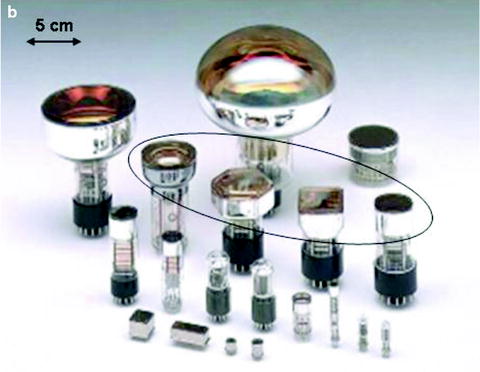
Fig. 5.4
(a) The basic design and operating principle of scintillation detectors. (b) Photographs of PMTs. The PMTs circled are typical of those used in gamma cameras. (Adapted from Cherry SR, Sorenson JA, Phelps ME. Physics in nuclear medicine. 3rd ed. Philadelphia: Saunders; 2003, with permission)
In addition to their widespread use in gamma cameras and SPECT and PET scanners, scintillation detectors are used in well counters, intraoperative probes, organ (“thyroid”) uptake probes, and rectilinear scanners.
Nuclear Medicine Instrumentation
Intraoperative Probes
Intraoperative probes (Fig. 5.5), small, handheld counting devices, are now widely used in the management of cancer: most commonly, to more expeditiously identify and localize sentinel lymph nodes and thereby reduce the length and potential morbidity of cancer surgery and to identify and localize visually occult disease at surgery following systemic administration of a radiolabeled antibody or other tumor-avid radiotracer. Although intraoperative probes have been used almost exclusively for counting x-rays and γ-rays, beta (negatron and positron) probes constructed with plastic scintillators and small field-of-view intraoperative gamma cameras have also been developed. Intraoperative gamma probes are available with either scintillation or semiconductor (ionization) detectors. Scintillation detector-based probes have the advantage of relatively high sensitivity (mainly because of their greater thickness, ∼10 mm, versus only ∼1 mm in ionization detectors), especially for medium- to high-energy photons. Disadvantages include bulkiness and relatively poor energy resolution and scatter rejection. In some scintillation-detector intraoperative probes, the light signal from the crystal is guided to a remote PMT through a flexible fiber-optic cable, allowing the probe assembly to be made relatively light and compact and more like a surgical instrument but with some loss of the light signal. Semiconductor-based probes are compact and provide better energy resolution and scatter rejection. However, defects in their crystal structure can trap electrons produced by radiation and thus reduce the total charge collected. As a result of such incomplete charge collection due to “charge trapping,” statistical uncertainty (i.e., noise) is increased and the photopeaks in energy spectra are broadened, that is, the otherwise excellent energy resolution of semiconductors is somewhat degraded. To minimize this effect, semiconductor detectors are made relatively thin (only ∼1 mm), resulting in lower intrinsic sensitivity. Trapping can also be reduced by increasing the bias voltage across the detector but with more electronic noise and poorer performance. Although techniques for fabricating defect-free semiconductors and thus reducing charge trapping continue to be developed, the main disadvantage of semiconductor detectors remains their limited thickness and resulting lower sensitivity, especially for medium- to high-energy x-rays and γ-rays. Nonetheless, while scintillation detectors can be made thicker and therefore more sensitive, semiconductor detectors produce more electrons per x-ray and γ-ray stopped and therefore have superior energy resolution. To date, the few clinical studies directly comparing scintillation and semiconductor intraoperative probes have not provided a clear choice between the two types of probes—both appear to work reasonably well in practice.
Fig. 5.5
(a) Basic design of a gamma probe collimator. The collimator may be thought of as an extension of the detector shielding in the forward direction, that is, beyond the detector face in the desired counting direction. A collimator may be characterized by its aperture (generally, but not necessarily, equal to the width of the detector), its length, and its wall thickness. (b) The probe’s FOV, that is, the area of tissue from which unscattered x-rays or γ-rays may reach the detector increases with increasing distance from the collimator aperture. The volume of tissue from which unscattered x-rays or γ-rays may reach the detector is thus a 3D cone diverging outward from the collimator (the dotted line). (From Zanzonico P, Heller S. The intraoperative gamma probe: basic principles and choices available. Semin Nucl Med. 2000;30:33–48, with permission)
Organ Uptake Probes
Historically, organ uptake probes have been used almost exclusively for measuring thyroid uptakes of radioiodine (or 99mTc-pertechnetate) and are thus generally known as “thyroid” uptake probes. The uptake probe is a radionuclide counting system consisting of a wide-aperture, diverging collimator, a NaI(Tl) crystal (typically ∼5 cm thick by ∼5 cm in diameter), a PMT, a preamplifier, an amplifier, an energy discriminator, and a gantry (stand). Commercially available thyroid uptake probes are generally supplied as integrated, computerized systems with automated data acquisition and processing capabilities, yielding results directly in terms of percent uptake. Nowadays, thyroid uptake measurements are commonly performed using planar scintigraphic images of the neck and region-of-interest (ROI) analysis.
Rectilinear Scanners
The rectilinear scanner, developed by Benedict Cassen in the 1950s, was the original Nuclear Medicine imaging device and predated the gamma camera. Nowadays, however, it is rather uncommon, particularly in the USA. Because of their substantially lower cost, however, they are still used in Europe by some endocrinologists in the management of thyroid disease. A rectilinear scanner consists of a small-area, relatively thick NaI(Tl) crystal fitted with a multi-hole focused collimator. The detector assembly travels transversely across the patient, then longitudinally along the patient in small steps, and finally transversely back across the patient, until a predefined scanner area has been imaged. Rectilinear scanners thus acquire images point by point, where the optimum sampling point is defined by the focal point of the converging collimator (i.e., the point beyond the collimator face at which the axes of the angled apertures intersect). Rectilinear scanners are notoriously insensitive, however, requiring 20 min or more to acquire an image of a normal-size thyroid. Spatial resolution and sensitivity vary sharply as a function of the distance from the focal plane (i.e., the plane in which the focal point lies). The thyroid gland is normally a rather flat, superficial structure, and the impact of these effects is minimized by adjusting the collimator aperture-to-neck (skin) distance such that the gland lies in the focal plane.
Gamma Cameras
Developed in the late 1950s by Hal Anger, the gamma camera (Fig. 5.6), also known as the scintillation or Anger camera, quickly replaced the rectilinear scanner as the predominant imaging device in Nuclear Medicine—mainly because its large detector area allowed simultaneous and therefore rapid data acquisition over a large area of the body. Gamma camera crystals vary in thickness from ¼″ (yielding the best spatial resolution but lowest sensitivity) to 1″ (yielding the highest sensitivity but coarsest resolution), with 3/8″-thick crystals providing the optimum balance between sensitivity and resolution and remaining the most widely used for general gamma camera imaging. Gamma camera NaI(Tl) crystals are nowadays most commonly rectangular in shape and up to ∼50 × 60 cm in area.
Fig. 5.6
Basic design of a gamma camera, consisting of a multi-hole collimator, a thin large-area NaI(Tl) crystal, a 2D array of PMTs and associated electronics (high-voltage power supply, preamplifier, and amplifier), position logic circuitry, energy discriminator, and image display. Note that there are actually two position logic circuits—for the determination separately of the x– and y-positions of the scintillation within the crystal. Note further that the output signal from each PMT is actually split into three parts, one (the z pulse) for the determination of the energy of the incident radiation as well as one each for the determination of its x– and y-positions. The left inset shows a photograph of the 2D PMT array backing the crystal in a typical rectangular field-of-view gamma camera. The right inset shows a drawing of a portion of a parallel-hole collimator, identifying the dimensions—aperture diameter, septal thickness, and septal length—of such a collimator. The “desirable” events (arrows labeled “1”) are unscattered (i.e., photopeak) photons traveling in a direction parallel or nearly parallel to the axes of the apertures and thus yielding correctly positioned counts in the gamma camera image. “Undesirable” events include scattered as well as unscattered photons traveling in a direction oblique to the axes of the apertures (2) and thus eliminated by attenuation by one or more collimator septa; septal penetration (3), that is, unscattered photons traveling in a direction oblique to the axes of the apertures yet passing through the septa and yielding mispositioned counts; scatter (4), that is, photons undergoing Compton scatter within the patient and either eliminated by energy discrimination or not eliminated and yielding mispositioned counts. (Adapted from Cherry SR, Sorenson JA, Phelps ME. Physics in nuclear medicine. 3rd ed. Philadelphia: Saunders; 2003, with permission)
The gamma camera collimator, almost always comprised of lead, “directionalizes” the incoming radiation: any radiation traveling obliquely to the axes of the holes (apertures) will strike the lead walls (septa) between the holes and not reach the crystal, thereby allowing only radiation traveling perpendicular to the crystal to pass through the apertures and contribute counts to the resulting image. A certain fraction of photons striking the septa will actually pass through them and reach the crystal; this phenomenon, which degrades image quality and is more severe the higher the energy of the x-rays or γ-rays being imaged, is known as septal penetration. Nowadays, parallel-hole collimators, in which the apertures and septa are parallel to one another, are used almost exclusively. However, converging (magnifying) and diverging (minifying) collimators, in which the apertures and septa are angled in such a way that lines along the axes of the apertures intersect, respectively, on the patient and the crystal side of the collimator, are also available. Likewise, single-aperture pinhole collimators, most commonly used for thyroid imaging because of their pronounced magnifying effect, are available as well. Like all non-parallel-hole collimators, however, converging, diverging, and pinhole collimators suffer from geometric distortion, that is, distance-dependent magnification or minification.
Gamma camera collimators are “rated” with respect to energy and resolution/sensitivity. Low-energy, or “technetium,” collimators are designed to image radionuclides emitting x-rays and γ-rays less than 200 keV in energy, including, most notably, 99mTc (photopeak energy: 140 keV) as well as 201Tl (68–80 keV), 123I (159 keV), and 57Co (124 keV). Medium-energy, or “gallium,” collimators are designed for radionuclides emitting x-rays and γ-rays 200–300 keV in energy, including 67Ga (93, 185, and 300 keV) as well as 111In (172 and 247 keV). High-energy, or “iodine,” collimators are designed to image radionuclides emitting x-rays and γ-rays greater than 300 keV in energy, including 131I (364 keV). In progressing from low- to medium- to high-energy collimation, the collimators are made longer and the septa thicker in order to interpose more lead between the patient and the crystal and to thereby maintain septal penetration (i.e., the percent of counts in an image attributable to photons that penetrate septa) at or below an acceptably low level, typically set at 5%. This, in turn, reduces the overall fraction of emitted x-rays and γ-rays reaching the crystal. To compensate, at least in part, for the resulting lower sensitivity, the apertures are typically made wider in progressing from low- to medium- to high-energy collimators. This, however, degrades spatial resolution. Overall, therefore, gamma camera images are progressively poorer in quality for radionuclides emitting low- versus medium- versus high-energy x-ray and γ-ray because of a combination of increased septal penetration with increasing photon energy, lower sensitivity because of the longer collimation, and coarser resolution because of the wider apertures. For each energy rating, collimators may also be rated as “general-purpose” (or “all-purpose”), “high-resolution,” or “high-sensitivity.” High-resolution collimators have narrower apertures (and therefore lower sensitivity) and high-sensitivity collimators have wider apertures (and therefore coarser resolution), respectively, than general-purpose collimators. In instances where a radionuclide emits significant numbers of photons of different energies, it is the highest-energy photon which dictates the collimator to be used. For example, a medium-energy collimator must still be used to image 67Ga (photon energies: 93, 185, and 300 keV) even if only the two lower-energy (i.e., the 93 and 185 keV) photons are used for imaging. For some older systems, only two, rather than three, photon energies can be imaged simultaneously.
Related posts:
Stay updated, free articles. Join our Telegram channel

Full access? Get Clinical Tree


