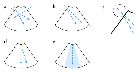
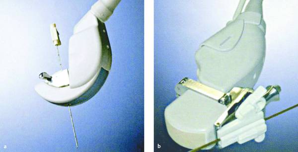
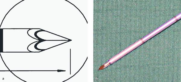
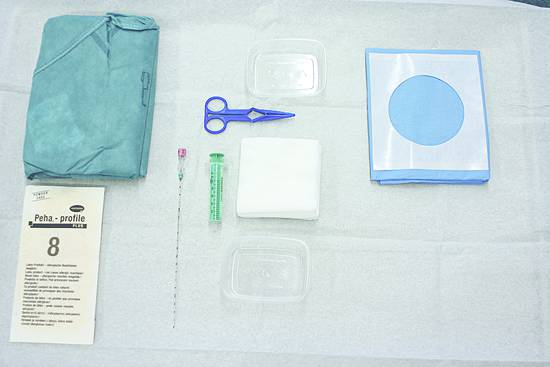
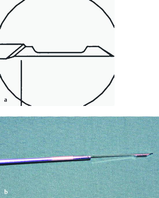
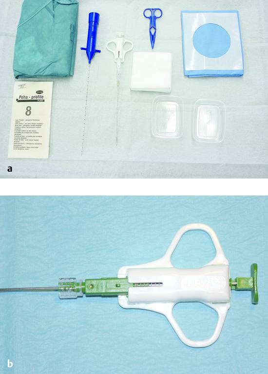
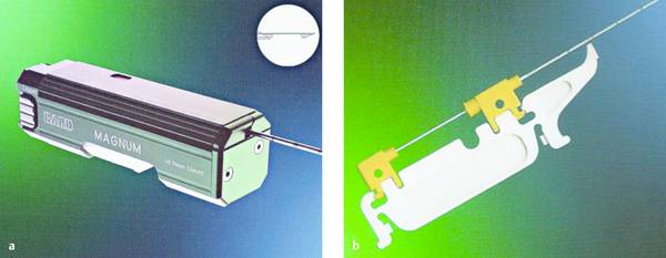
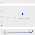
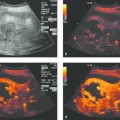
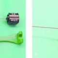
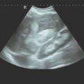
Interventional Materials and Equipment Ultrasound-guided interventional procedures may be performed for diagnostic as well as therapeutic reasons. The goal of diagnostic procedures is to collect tissue or fluid samples for analysis, using percutaneous needles of various sizes and designs. One drawback of using large-caliber needle systems was already noted in an article published over 60 years ago1: “When we consider that percutaneous drainage rates need to be limited, it is pointless to use very large needles or trocars since the outflow must often be interrupted by clamping the tube so that fluid is not evacuated too rapidly.” In the age before adequate imaging techniques were available, necessary drain size could usually be determined only by percutaneous aspiration, prompting an early policy statement that percutaneous drainage should never be attempted without prior needle aspiration.2 An empyema, for example, required the placement of a drain approximately 15 to 20 mm in diameter. Milestones in the development of biopsy techniques are summarized in ▶ Table 2.1. The most widely practiced ultrasound-guided biopsy techniques are a “blind” biopsy performed at a marked skin site after ultrasound localization, the freehand technique with one hand holding the transducer and the other guiding the needle, and the use of a needle guide or special biopsy transducer (▶ Table 2.2). In the freehand technique, the needle is guided freely by the operator’s hand. The challenge is to keep the needle at a proper angle to the imaging plane so that it is visible at all times. The main advantage of this technique is its flexibility. This makes it easier, for example, to interpose a sufficient rim of normal liver tissue between a superficial lesion and the liver capsule to minimize bleeding. Using a side-mounted needle guide has the advantage of providing the same image quality as without a biopsy attachment. Most guides are adjustable to two different needle angles (▶ Fig. 2.1, ▶ Fig. 2.2). Biopsy can be performed from the right and left sides by rotating the display. Fig. 2.1 Biopsy techniques. a Freehand technique allows for multiple, variable needle paths. b A separate needle guide mounted on the transducer can usually be adjusted for several angles of needle insertion. c The first 2–4 cm cannot be visualized with this technique. d The needle is introduced through a biopsy transducer. e Visualization may sometimes be obscured by local infiltration anesthesia. (Source: reference17.) Fig. 2.2 Devices manufactured by Hitachi. a Biopsy transducer. b Ultrasound transducer with a detachable needle guide. (Source: reference17.) With a biopsy transducer, the needle can be introduced through the transducer at various angles by means of a sterilizable insert. Usually the insert has channels that determine the angle of needle insertion, and the prospective needle path is displayed as a virtual line on the ultrasound screen. This line can also be displayed with transducers that have a screw-on biopsy attachment. In this case the angle of insertion is defined by a stop on the needle guide. Only the biopsy inserts or detachable needle guides require sterilization. The advantage of using a biopsy transducer with an integrated guide channel is that it permits accurate needle monitoring even with a limited acoustic window or long biopsy path. One disadvantage is a slight loss of image resolution in the area of the biopsy insert, which is devoid of piezoelectric crystals. A side-mounted needle guide creates a superficial blind spot, making it more difficult to sample lesions close to the transducer. This is not a problem in practice, however, because high-frequency transducers are usually used for superficial lesions and the needle can be guided without difficulty owing to the short pathway next to the probe. Since high-performance transducers are expensive, most biopsy transducers are offered in the low-frequency range (▶ Table 2.3). Biopsy needles have a sharp, beveled tip that cuts the tissue when the needle is advanced. They enter the body more easily than a sharp-pointed needle without a cutting edge, which would damage the tissue and cause considerably more pain. Needles with an outer diameter <1 mm are classified as “fine” needles; larger-caliber needles with an outer diameter of 1 mm or more are classified as “coarse.”18 Biopsy needles are manufactured from medically approved stainless steel alloys composed of iron, chromium, nickel, molybdenum, or manganese that are resistant to corrosion, acids, and alkalis. Chromium (at least 13%) imparts rust resistance, while nickel makes the alloy resistant to acids. For example, the designation chromium–nickel steel 18/10 means that the alloy consists of 18% chromium, 10% nickel, and 72% steel. Some needles are also coated to make their insertion as painless as possible. Silicone is often used as a biocompatible coating material. The increasing use of magnetic resonance imaging (MRI) has prompted the development of compatible needles made of carbon-fiber–reinforced plastics. These needles have the high stiffness of the composite material, a high strain to fracture, and excellent chemical stability. Current needles of this type are up to 20 cm long and are typically 1.2 mm in diameter. They are stiffer and stronger than metallic needles. A triple-lumen needle with an outer diameter of 1.2 mm and a biocompatible surface coating may contain three working channels with inner diameters of, say, 272 μm, 312 μm, and 612 μm. Various systems are available for designating needle size. Needle diameters are most often stated in terms of millimeters or gauge. Other options are the Pravaz system (Gr) introduced by the French orthopedist Charles G. Pravaz (1791–1853) and the Charrière (Ch) or French (F) systems. The most popular unit for designating outer needle diameter is gauge, which is based on the America Wire Gauge (AWG) system. It was originally used to designate wire thickness and indicated the number of drawing operations needed to reduce a wire to the desired diameter (▶ Table 2.4). Thus, the higher the gauge number, the thinner the needle. For example, a 19-gauge needle is classified as “coarse” while a typical “fine” needle would be 22-gauge. There is no fixed linear relationship between the individual gradations, but the following formula gives a good approximation: It is common to see both the millimeter and gauge systems used in everyday practice. The gauge system was introduced by J. R. Brown in 1857 and was known initially as the Brown & Sharp (B&S) gauge. In accordance with ISO and DIN specifications, the hub for connecting a biopsy needle to a handle or syringe is color-coded to provide a clear indication of needle size (▶ Table 2.4). In the manufacture of biopsy needles, sheet steel is wrapped around an arbor, welded, and drawn out into fine, thin-walled tubing, which is then cut to the necessary lengths and ground to the desired tip configuration. The length of a biopsy needle depends on the distance to the target site and, when a biopsy transducer is used, on the necessary needle length outside the body. The same considerations apply to the use of a needle guide, which is also associated with a longer needle path. Needle lengths from 10 to 22 cm are most commonly used.19 In principle, an excessive needle length is unfavorable only if the target site is only 1 to 2 cm deep, as this would make the long needle unstable. In all other cases it is best to add a certain reserve length to make sure the needle will be long enough. The selection of needle size is always a trade-off. In the biopsy of parenchymal organs, the pathologist requires a tissue sample with sufficient architectural organization, implying the use of a large-caliber needle. For example, it is desirable in liver biopsies to obtain 8 to 15 portal fields. Although it has been reported in the literature that complication rates increase with needle size,20 published results to date are contradictory and inconclusive.21,22 In the case of focal hepatic lesions, however, available data do appear to indicate that the risks of fine needle biopsy (<1 mm) are less than with larger needles.23,24 On the other hand, practical experience has shown that 1.2-mm (18-gauge) core-biopsy or Trucut needles provide good diagnostic accuracy with minimal hemorrhagic complications. This is consistent with our own technique, which permits even rare entities to be diagnosed with a high degree of confidence. The retrieved specimen length also has an important bearing on diagnostic accuracy. In the case of liver biopsies, for example, it has been found that tissue cores <1 cm long do not permit an accurate evaluation of viral hepatitis (grading and staging) and that the analysis of shorter cores may underestimate the severity of disease.25 Multiple tissue sampling improves the chance of obtaining representative material but also increases the complication rate, requiring that a reasonable trade-off be made. This compromise depends on the organ biopsied and on the access route and is an important consideration in organ biopsies. In the biopsy of circumscribed liver lesions, tissue samples should be taken from the edge and center of the lesion. In biopsies using an ultrasound contrast agent, it is easy to distinguish vascularized tissue from necrotic. This is important because the biopsy of a necrotic area would yield a nonrepresentative sample. The question whether the risk of needle track seeding correlates with the size or type of needle is unresolved and will probably remain so in the future due to the extremely small case numbers. There is similar uncertainty regarding the complication rates associated with different needle types. A 22-gauge needle is sufficient for aspirating watery exudates or transudates, while an 18-gauge or larger needle should be used for pus.26,27 Tissue can be sampled by aspiration biopsy or by a cutting or core biopsy technique.28,29 Chiba-type needles with a short beveled tip are used for the aspiration of fluids. The lumen size, and thus the outer needle diameter, should conform to the consistency of the aspirated fluid. Other tip configurations are shown in ▶ Fig. 2.3 and ▶ Table 2.5. Fig. 2.3 Biopsy needles. a Crown-point needle with a trocar-tip stylet. b Needle with a beveled tip, sandblasted distal segment, and centimeter depth markings. (Source: reference17.) The most widely used tip configurations for biopsy needles are the short beveled tip and trocar tip. Neither is inherently superior, and technical considerations will usually guide the selection of a particular needle tip geometry. With the cannulas used for aspiration and core biopsies, a central trocar point can provide a tip with uniform circumferential sharpness. With needles for collecting cytologic material and Trucut needles (see below), a beveled tip is technically easier to produce, provides high needle sharpness, and makes for a smooth transition between the outer cannula and inner stylet. But if the needle will be rotated on its long axis during the biopsy, a central point is advantageous for fixation of the needle tip. This principle is illustrated by the triple-crown tip (Jamshidi needle) used for iliac crest biopsy. Manufacturers use various methods of roughening the surface of the distal needle shaft to facilitate needle tip tracking in the ultrasound image. In most cases this is done by sandblasting the distal 10 to 15 mm but is uncertain whether this actually does improve needle visualization. A needle that is oblique to the image plane is almost always clearly visible. Visualization is a problem only if the needle is not angled relative to the beam, in which case the operator must often rely on indirect signs for needle localization, such as concomitant tissue movements. One disadvantage of surface roughening is the potentially higher risk of needle track seeding, although there is no hard evidence at present to support this concern. As a general rule, only needles with a stylet should be used to obtain representative organ tissue (e.g., in a percutaneous renal or liver biopsy). This prevents tissue contamination from the needle tract that might cause an erroneous diagnosis. The Luer lock connector has become standard for all hollow needle systems. If a therapeutic agent is to be administered through the indwelling needle, a syringe with a screw-on attachment should be used to prevent accidental hub separation that could spray caustic material onto the patient and staff. The Luer lock connector has become standard for all hollow needle systems. A complete table setup is shown in ▶ Fig. 2.4. An example is percutaneous ethanol injection for hepatocellular carcinoma. The agent is injected through 20- to 22-gauge needles that are sealed at the end and have side holes over a length of 1 to 2 cm at the distal end. These side holes provide a more uniform, and thus more effective, dispersion of the alcohol into the tumor tissue. Fig. 2.4 Table setup for a Chiba fine needle biopsy. If the lesion is superficial and there is little danger of aspirating foreign material during needle insertion, a cannula without a stylet can be used. This applies mainly to thyroid and lymph node biopsies. Advancing the plunger slightly on reaching the biopsy site to clear the needle of any extraneous material is problematic for hygienic and other reasons and cannot be recommended. It could cause cellular contamination that would hamper later evaluation by the pathologist, and it might also degrade image quality. It is better to describe the needle pathway to the pathologist so that he or she can identify any extraneous cellular material, which often consists of skin particles. The tissue material is retained in the cannula by suction applied to an attached syringe (▶ Fig. 2.5). Fig. 2.5 a Fully automated core biopsy needle (Autovac, Bard GmbH). b Semiautomated vacuum needle (Biomol, Pflugbeil GmbH). (Source: reference17.) Usually the suction is maintained by a syringe with a locking mechanism. Another option is to use a handle that mounts on the syringe and allows the operator to vary the negative pressure with one hand as needed (e.g., Aspir-Gun by Helmuth Industries, UK). Caution It is important to stop the suction before removing the needle from the biopsy site. Otherwise the aspirated tissue will be sucked into the syringe, making it extremely difficult to process, and additional tissue may be aspirated from the biopsy tract during needle removal. The classic representative of the suction biopsy needle is the Menghini needle (Surecut needle30,31). The Menghini needle is filled with saline solution to prevent aspiration of foreign material as the needle is advanced. The tissue is cored with a sharp cannula, and the specimen is retained in the cannula by a slight negative pressure (“one-second liver biopsy”32). With manual systems, the operator draws back on the plunger to create suction and retain the tissue core. This technique does not entirely preclude specimen loss, however, and there is still a very small risk of needle track seeding. The original technique for a “Menghini biopsy” consisted of advancing the needle to the biopsy site, applying suction with a locking syringe, and then inserting and withdrawing the needle quickly with a jabbing motion of the wrist. Because this manual technique requires some experience and gives an imprecise penetration depth in focal lesions, automated suction biopsy devices were developed.33 The Vim–Silverman needle, once widely used, functions by the suction biopsy principle but is rarely used today. In all cases the core needle should be rotated after insertion to help detach the tissue core from its bed. Retention mechanisms have been developed that occlude the distal needle opening to prevent specimen loss. One such mechanism has a small leaf spring that secures the tissue core within the cannula. In the BioPince needle manufactured by Peter Pflugbeil GmbH, a spring clip automatically hooks into a slot near the needle tip after the instrument is fired, trapping the core sample within the cannula without a vacuum system.34,35 The specimen is then safely extracted within the closed system. Everyday experience has shown, however, that the standard automated and semiautomated systems almost always retain the tissue core with no real need for a complicated needle design. After the needle is removed from the body, the stylet is advanced to expel the collected material. At the end of the procedure, a syringe can also be used to force air through the cannula to recover any residual particles left in the needle. For more information about specimen processing and pitfalls in cytologic analysis, we refer the reader to the detailed publications of Jenssen et al.36,37 The needle should not be flushed with sodium chloride solution or water, as this might cause changes in the cellular material. Cutting needle biopsies employ either an end-cutting or side-notch (Trucut) technique for sampling tissue. Examples are the Franseen needle and the Otto needle, which are distinguished by the geometry of the cutting edges at the cannula tip. The first end-cutting needle was the Otto needle, available in fine and coarse sizes with two cutting teeth at the tip.38 Because these needles must be simultaneously rotated and advanced at the biopsy site, practitioners rarely use them today, and they do not merit further discussion here. Although the Trucut needle harvests only a semicylindrical tissue core, this technique offers a decisive advantage (▶ Fig. 2.6, ▶ Fig. 2.7, ▶ Fig. 2.8). The inner stylet, which has a side notch 10 to 20 mm long (throw), is advanced into the lesion. After tissue has entered the notch, the outer cutting cannula is advanced over the stylet to slice off and secure the specimen within the cannula. This mechanism protects the specimen and prevents seeding of the needle track with tumor cells. The main disadvantage is that Trucut biopsies require larger-caliber needles than other techniques to obtain specimens of equal quality. The side-cutting technique was introduced by Lindgren in the early 1980s.39 There are devices on the market in which the cannula and stylet can be controlled by hand, making the puncture and cutting actions a purely manual process. An example is the Uni-Core biopsy needle (14–21 gauge, 11.5–20 cm length). First the closed needle is advanced to the lesion. Then the stylet is pushed manually into the lesion, and the cannula is slid manually over the stylet, cutting and trapping the tissue specimen. One disadvantage is that the needle must be operated with two hands, and so a second examiner is needed to hold the ultrasound transducer. In semiautomated systems, the stylet is advanced manually but the cannula is spring-loaded and is fired at the touch of a button, cutting off the tissue in the specimen notch (▶ Fig. 2.6). The instrument is cocked before the procedure. Various disposable models of these needles are available commercially. Also available are biopsy guns made of metal that can be reused for many years as they are easy to clean and sterilize. The only disposable component is the needle. The throw length of the needle is preset to the desired biopsy depth before use. Fig. 2.6 Trucut needle with the notched inner stylet deployed. a Schematic drawing. b Photograph. Fig. 2.7 Table setup for a percutaneous biopsy. a With an automated core biopsy needle and Trucut needle. b Close-up view of the semiautomated coaxial device. Fig. 2.8 Biopsy devices manufactured by Bard, Murray Hill, New Jersey, USA. a Fully automated. b Trucut needle.
2.1 General Considerations on Interventional Procedures
2.1.1 Brief Historical Introduction
Year
Procedure
Localization
First describer
Source
1851
Percutaneous tumor biopsy
Palpation, percussion
Lebert
3
1853
Breast tumor biopsy
Palpation, percussion
Paget
4
1883
Lung biopsy, identify infecting organism in pneumonia
Palpation, percussion
Leyerden
5
1883
Liver biopsy
Palpation, percussion
Ehrlich
6 ,7
1925
Special technique for fine needle biopsy
Palpation, percussion
Martin, Ellis
8
1930/1931
Bone marrow aspiration and biopsy
Palpation, percussion
Martin, Coley
9
1935
Vertebral body needle biopsy
Palpation, percussion
Robertson, Ball
10
1939
Lung tumor biopsy
Radiography
Blady
11
1951
Percutaneous pancreatic biopsy
Radiography
Kistland
12
1952
Thyroid biopsy
Palpation
Söderström
13
1952
Percutaneous renal biopsy
Radiography
Lindblom
14
1958
One-second liver biopsy
Percussion
Menghini
15
1967/1977
Lymph node biopsy, transperitoneal
Radiographic guidance
Nordenström, Zornoza
16
1972
Percutaneous liver biopsy
Ultrasound
Rasmusen
14
1975
Percutaneous pancreatic biopsy
Ultrasound
Hancke
16
2.1.2 Biopsy Principles and Techniques
Freehand Biopsy, Needle Guide Attachments, and Biopsy Transducers
Technique
Advantage
Disadvantage
Freehand
Flexible angles, free guidance
Needle may move out of the image plane
Needle guide
Routine transducer can be used
Better targeting
Good needle tip visualization
Needle may deviate from desired biopsy path
Longer pathway through the tissue
Blind spot in the first 2–4 cm
Biopsy transducer
Short path to target
Needle tip may be more difficult to see because it is parallel to the ultrasound beam and cannot reflect sound waves
Local infiltration anesthesia may obscure vision
Biopsy Transducers
Designation
Frequency range
THI and CHI
Remarks
EUP B514
2–5 MHz
Yes
Needle is inserted through a sterilizable insert in a normal-size convex transducer
EUP B512
2–5 MHz
Yes
Sterilizable needle guide attaches externally to a small-footprint convex transducer
Abbreviations: THI, tissue harmonic imaging. CHI, contrast harmonic imaging.
2.1.3 Needle Systems
Needle Technology
 (2.1)
(2.1)
Size in gauge
14
15
16
17
18
19
20
21
22
23
25
Outer diameter (mm) based on ISO/DIN 9626
2.1
1.8
1.6
1.4
1.2
1.1
0.9
0.8
0.7
0.6
0.5
Charrière/French (Ch, F)
6.3
5.4
4.8
4.2
3.6
3.3
2.7
2.4
2.1
1.8
1.5
Pravaz system (Gr)
1
2
12
16
23
Color code based on ISO 6009 or DIN 13095
Light green
Blue-gray
White
Purple
Pink
Cream, ivory
Yellow
Dark green
Black
Dark blue
Orange
Needle Length and Size
Needle Tip Configurations
Tip configuration
Characteristics
Recommended use
Trocar
Three-sided point
Suitable for almost all applications
Single bevel (faceted, US bevel, MS bevel)
Oblique bevel with a fitted stylet at the tip
Suitable for almost all applications
V bevel
Noncoring with five cutting surfaces
Spinal anesthesia
Pencil point
Noncoring, inflow and outflow through a side hole
Spinal anesthesia
Huber tip
Angled (10%) behind the heel
Used for filling ports
Quincke point
Faceted tip similar to lancet point
Spinal anesthesia
Triple-sharpened point
Atraumatic
Bone marrow biopsy
Suction Biopsy Systems
Suction Needle without a Stylet
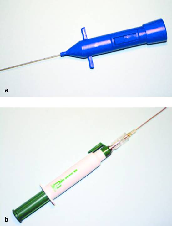
Menghini Needle and Other Suction Needles with a Stylet
Cutting Biopsy Systems
End-Cutting Needles
Trucut Needle
Related posts:
 Informed Consent
 Percutaneous Sclerotherapy of Cysts
 Contraindications, Complications, and Complication Management
 Fine Needle Aspiration Biopsy and Core Needle Biopsy
 Indications for Diagnostic Interventions in the Abdomen and Thorax (Liver, Pancreas, Spleen, Kidneys, Lung, Other Sites)
 Thoracic Interventions
Stay updated, free articles. Join our Telegram channel

Full access? Get Clinical Tree


