Key Points
- ▪
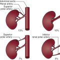
IVUS can be used to characterize, with high resolution, the architecture of the aorta and, importantly, the architecture of its branch vessel ostia, as well as aortic plaque, thrombus, and intimal flaps.
- ▪
IVUS can be used to guide thoracic and abdominal aortic and iliac-level stent deployment.
Introduction
The continued expansion of endovascular devices and procedures has led to a major shift in the treatment of vascular disease. These procedures, which were first successful in small-caliber vessels, have quickly become quite useful in larger-caliber vessels such as the aorta and iliac arteries. The continued success and advancement of these procedures depends on the ability to image and evaluate the patient’s anatomy adequately prior to the procedure, as well as during it. Accurate assessment of the patient’s anatomy and disease are crucial in the selection of the appropriate device. Furthermore, during the procedure, precise imaging is needed to confirm the initial computed tomography (CT) interpretation of the anatomy, to evaluate landing zones or neck length, and to confirm that the devices are in the correct location and are fully expanded. Intravascular ultrasound (IVUS) is ideally suited to provide these real-time imaging needs. The use of IVUS can add another level of imaging accuracy to further increase the information available to the endovascular surgeon. The goals of this chapter are (1) to demonstrate the utility of IVUS imaging for thoracic and abdominal aorta and iliac artery interventions and (2) to be an atlas or guide to image interpretation of these various anatomies.
Intravascular Ultrasound Imaging
Catheters
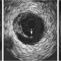
Two types of peripheral IVUS catheters are available for use: multielement phase array catheters and mechanically rotating element type catheters. Mechanical IVUS catheters rotate a small transducer located at the tip of the catheter using a flexible, high-torque cable that extends the length of the device ( Fig. 13-1 ). The phase array catheters incorporate a miniature integrated circuit with 64 imaging elements located on the tip of the catheter ( Fig. 13-2 ). Both catheters can be used over a 0.035-inch guidewire and can pass through 9F sheaths. Two slight advantages of the phase array catheter are the lack of moving parts and the concentric guidewire location, which allows easy passage through tortuous anatomy and has no guidewire artifact. The key to optimizing IVUS catheter use is to not delay the procedure or add additional guidewire exchanges. IVUS should provide quick and easy assessment of the device and/or anatomy.


Rotational Orientation
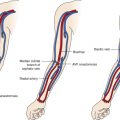
On-screen image orientation, although not crucial in the diagnosis, can be helpful for image interpretation. The image can be easily electronically rotated by pushing a button on the IVUS machine. The investigator should avoid rotating the catheter, especially in tortuous anatomy. The best way to identify vessel orientation is to use known anatomical landmarks. For example, as the catheter crosses the aortic bifurcation, it is possible to rotate the IVUS display electronically such that the common iliac arteries are positioned side-by-side, in a correct anatomical location. Occasionally, this anatomical arrangement is not true, especially in tortuous, dilated vessels, and it is necessary to check the alignment against other parameters. The location of anterior visceral vessels (i.e., celiac and superior mesenteric arteries, renal vein) are also useful when imaging in the abdominal aorta. For the iliac bed, the posterior-medial position of the internal iliac artery orifices can be used to adjust for angulations.
Longitudinal Grayscale Imaging
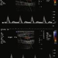
The longitudinal grayscale image is obtained by mechanically withdrawing the catheter through the vessel at a controlled rate. The cross-sectional images are then stacked by the processing unit and rotated 90 degrees to produce a longitudinal view, very similar to an angiogram, except that detailed wall morphology and luminal dimensions are depicted. Length measurements can be made if a mechanical pull-back device is used. However, the current pull-back devices available are too slow to use for peripheral-aortic type of procedures. Therefore, length measurements cannot be obtained.
Measurements
Luminal dimensions and wall thickness determined by IVUS of normal and minimally diseased arteries (both in vitro and in vivo) are accurate to within 0.05 mm. The luminal cross-sectional areas calculated from biplanar angiograms and measured from IVUS correlate well for normal or minimally diseased peripheral arteries in vivo. In severely diseased vessels with elliptical lumens, angiography is less accurate in calculating luminal cross-sectional area and tends to underestimate the severity of atherosclerosis in the wall compared with IVUS. Studies have shown that IVUS is an important intraoperative tool in evaluating aortic diameters for endovascular aneurysm repair and that the technique has proven efficacy in the characterization of vessel diameter, stenosis, and morphology.
When dealing with the aorta, angulations caused by tortuosity may also cause an elliptical image of the vessel lumen. This is especially true in the thoracic arch. When this occurs, the minimal diameter (minor axis) should be used to measure the diameter. Investigators have demonstrated that the minor axis is the most accurate measurement in angled images and/or tortuous anatomy. In another study, investigators found that off-center IVUS measurements may not be as accurate as centerline CT measurements. In a study comparing two-dimensional versus three-dimensional CT scans for aortic measurement, investigators found that the minor axis measurement on axial CT scans had a high correlation with the centerline three-dimensional measurements. Their conclusion was that the minor axis measurement can substitute for three-dimensional centerline measurements in most situations. The authors continue to use three-dimensional centerline CT scans for preoperative evaluation and sizing but use minor axis IVUS diameter measurement, at systole, to select the appropriate endoluminal device size.
Therapeutic Interventions
Aortoiliac Disease
IVUS can provide important diagnostic information that can alter the conduct of selected endovascular procedures. It is especially useful when the procedure requires deployment of arterial stents. Proper sizing, stent selection, and deployment are critical for improving chances of long-term patency. Researchers have shown that inadequate stent expansion can lead to early thrombosis or stent migration, whereas overexpansion can result in excessive intimal hyperplasia or vessel perforation. IVUS is effective in assessing the result of the primary intervention, establishing the need for stenting, and guiding stent deployment. Studies have found that it improves long-term patency rates. Additional studies have revealed that contrast angiography, which is thought to be the “gold standard” for assessing endovascular therapy, has limitations in the evaluation of stent-based procedures. Specifically, the monoplanar images produced with arteriography show the details only of the outer edges of the artery and stent. This limits the ability to evaluate stent-to-vessel apposition adequately. One study demonstrated that vessel size and lumen diameter were underestimated 62% of the time by arteriography and that 40% of the stents placed in the iliac arterial system were underdeployed, which might lead to related treatment failure.
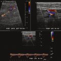
It is also possible to use IVUS to differentiate intimal versus subintimal guidewire location and to choose appropriate endovascular technique based on that data. In cases where the investigator cannot reenter the true lumen, research has demonstrated that IVUS can be used to guide a trans-septal needle from the subintimal space to the true lumen, followed by successful angioplasty and stenting. Figure 13-3 illustrates the use of IVUS to determine guidewire location and assess the area of treatment for a total occlusion of the right iliac artery. Figure 13-3 A shows pre-IVUS images. The patient underwent treatment with bilateral iliac stents and primary stent ballooning, followed by IVUS. After the clinician used the same balloon to further dilate the stent, the patient had a final IVUS and angiogram, which can be seen in Figure 13-3 B.

IVUS can also be useful in cases where the quality of the fluoroscopic imaging is limited (due to equipment and/or size [density] of the patient) and when the investigator wishes to limit the amount of contrast. Once the clinician advances the guidewire past the lesion of interest, an IVUS catheter can completely interrogate the vessel morphology without the use of contrast or fluoroscopy. A radiopaque scale placed behind the patient can be used to identify the location of IVUS catheter at specific areas of interest. If this technique is used, the landmarks should be centered on the screen to eliminate fluoroscopic parallax or the fluoroscopic unit should be locked in place. Figure 13-4 illustrates this use of IVUS.


Endoluminal Grafts for Abdominal Aortic Aneurysm
IVUS can be an important adjuvant in the deployment and evaluation of endoluminal grafts for the treatment of abdominal aortic aneurysms. Currently, most of the preprocedural evaluations can be performed using contrast-enhanced spiral CT imaging. However, during the procedure, IVUS is useful to confirm diameters and lengths of proximal and distal fixation points as well as to ensure normal healthy arterial wall at those fixation points. Cinefluoroscopy and IVUS are complementary in enabling expedient placement of endoluminal grafts. The use of IVUS can significantly reduce the fluoroscopy time and contrast usage during the procedures, minimizing the exposure of both personnel and the patient. Several investigators have reported deploying both thoracic and abdominal endoluminal grafts without the use of contrast agents.
The authors commonly place the radiopaque scale beneath the patient, positioned parallel to the spine along the left psoas muscle, to locate the major landmarks such as the aorta just distal to the lowest renal artery, the aortic bifurcation, and the hypogastric arteries. At each given point, the IVUS catheter is centered on the fluoroscopic screen to eliminate fluoroscopic parallax, and the diameter is measured to confirm pre-CT measurements ( Fig. 13-5 ). If the aorta is tortuous and/or the IVUS image is elliptical, the minor axis is measured to determine diameter, as described earlier. The catheter is then retracted to the next landmark and measurement repeated.