Christine B. Chung MD
Lynne Steinbach MD
Anatomic Review
The long head of the biceps functions as a flexor and medial rotator of the shoulder. It is active in abduction and external rotation of the shoulder, assisting in limiting external rotation of the glenohumeral joint (1) and in preventing proximal migration of the humeral head (2, 3). The tendon arises from the long head of the biceps muscle within the upper third of the arm and courses superiorly through the intertubercular sulcus (bicipital groove) of the humerus, arcing over the humeral head as it passes as an intracapsular but extrasynovial structure inferior to the supraspinatus tendon, inserting on the supraglenoid tubercle and/or the glenoid labrum (4, 5) (Fig. 6.1). Variation in the anterior to posterior position of the superior attachment has been described by Vangsness et al. (5). In a dissection of cadaveric shoulders, although the most common site of attachment was characterized by a slab-like central attachment involving both the anterosuperior and posterosuperior labral tissue, variations occurred in which the long head of the biceps attached primarily to either the posterosuperior or anterosuperior labral tissue. This potential variation in attachment will become important when considering the distinction between normal variations in superior labral attachment from pathology. Portions of the long head fibers also support and form the anterior labrum. As a result of the close relationship to the glenoid labrum, this tendon contributes to superior and anterior glenohumeral joint stability (1, 6).
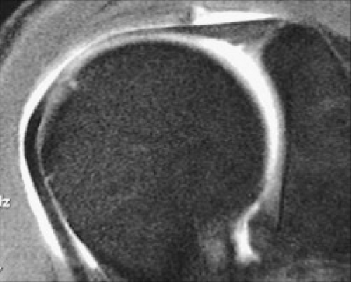 Figure 6.1 Oblique MRI of the long head biceps tendon. Intermediate-weighted fat-suppressed MR image oriented along the course of the long head of the biceps profiles the proximal attachment to the glenoid and labrum as well as showing the intra- and extra-articular segments. |
The biceps tendon is covered by several anatomic structures as it courses in the intertubercular sulcus. The pectoralis major tendon covers the intertubercular sulcus inferiorly, blending with the capsular ligament. More cranially, the biceps tendon is held in the bicipital groove by the transverse humeral ligament, believed to be an extension of the subscapularis tendon that covers the bicipital groove. Further cranial, when it becomes intra-articular, the biceps tendon is covered anteriorly by the coracohumeral ligament, superior glenohumeral ligament, and the supraspinatus and subscapularis tendons, which thicken the capsule and act as the chief stabilizers of the tendon. This region has been referred to as the rotator cuff interval capsule (Fig. 6.2). The coracohumeral ligament takes an origin from the proximal third of the dorsolateral aspect of the coracoid process with superficial fibers inserting at the greater and lesser tuberosities. The deep fibers insert on both the greater and lesser tuberosity and surround the tendon of the long head of the biceps as it exits the intertubercular sulcus to enter the articulation. The coracohumeral ligament (CHL) is best visualized in the axial plane (Fig. 6.3). The superior glenohumeral ligament (SGHL) originates at the supraglenoid tubercle along with the long head of the biceps. The SGHL is best identified in the axial imaging plane (Fig. 6.4). It follows the coracoid concavity in its midsubstance and inserts proximally at the lesser tuberosity where it fuses with the CHL to surround the long head of the biceps tendon as previously described. This reinforcement of the long head of the biceps tendon by the combined fibers of the coracohumeral and superior glenohumeral ligaments at the junction of the extra- and intra-articular biceps tendon has been referred to as the biceps tendon pulley. This insertion site is shown to best advantage in the sagittal imaging plane. The long head of the biceps tendon is seen on all imaging planes optimally identified with contrast or fluid within the articulation.
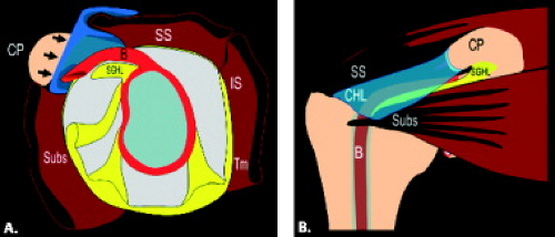 Figure 6.2 Diagrams of the rotator cuff interval. A: Sagittal diagram of the glenoid and capsule showing the RCI (arrows) defined as the space between the supraspinatus tendon (SS) and subscapularis tendon (Subs) that results from the interposition of the coracoid process (CP) between these two tendons. The anchor for the long head of the biceps tendon (B), the superior glenohumeral ligament (SGHL), and the rotator interval capsule (arrow) are depicted. B: Coronal diagram of the shoulder depicting the rotator interval capsule bordered superiorly by the supraspinatus tendon (SS) and inferiorly by the subscapularis tendon (Subs). It occurs as a result of the interposition of the coracoid process (CP) between these tendons. The long head of the biceps tendon (B) is also shown. The bursal-sided coracohumeral (CHL) and articular-sided superior glenohumeral ligament (SGHL) relationship is emphasized. |
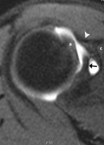 Figure 6.3 Proximal rotator cuff interval. Axial T1-weighted fat-suppressed MR image obtained after contrast injection into the joint shows the superior glenohumeral ligament (arrow) emanating from the superior glenoid, the coracohumeral ligament (arrowhead) arising from the coracoid process (C), and the biceps tendon (B). |
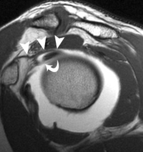 Figure 6.4 Rotator cuff interval and biceps pulley. Sagittal T1-weighted MR image obtained after contrast administration into the joint profiles the course of the coracohumeral ligament (arrowheads) and superior glenohumeral ligament (curved arrow) as they reinforce the biceps tendon at the junction of its intra- and extra-articular position. This region has been referred to as the biceps pulley and emphasizes the bursal-sided position of the coracohumeral ligament with respect to the articular-sided position of the superior glenohumeral ligament. |
Taking into consideration the anatomy of its constituents, Jost et al. (7) described the rotator cuff interval capsule in great detail documenting both a lateral and medial portion. The former was designated as that capsule lateral to the cartilage bone transition of the humeral head and consisted of four layers from superficial to deep, including the superficial fibers of the CHL, fibers of the supraspinatus and subscapularis tendons, deep fibers of the CHL, and the SGHL. The medial rotator cuff interval covered the cartilaginous humeral head and consisted of only the CHL superficially and the SGHL at the articular side. Throughout its course, the normal rotator cuff interval capsule should have a smooth contour with a thickness of approximately 2 mm as measured on sagittal images just lateral to the coracoid process (8). Insufficiency of the biceps pulley can lead to the clinical presentation of a snapping or subluxating biceps tendon (Fig. 6.5).
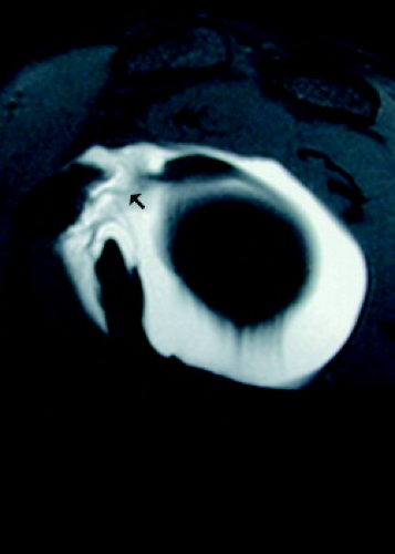 Figure 6.5 Rotator cuff interval tear. Sagittal T1-weighted fat-suppressed MR image after the administration of intra-articular contrast shows an abnormal rotator cuff interval capsule (arrow) with contrast extending to the undersurface of the coracoid consistent with the tear. Physical examination findings revealed a snapping sensation of the biceps with palpation. |
As previously noted, the long head of the biceps is an intracapsular but extrasynovial structure in the glenohumeral joint. The biceps is covered by a thin synovial lining, a reflection of the synovial membrane that ends distally as a blind pouch within the intertubercular sulcus. Hence, the sheath for the long head of the biceps tendon communicates with the glenohumeral joint. The presence of small amounts of fluid or contrast in the tendon sheath is common in asymptomatic volunteers (9). As a corollary, contrast and fluid normally flow into the biceps tendon sheath during an MR arthrogram (Fig. 6.6).
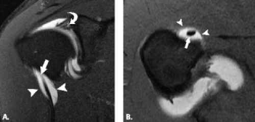 Figure 6.6 Biceps tendon synovial reflection. Coronal (A) and axial (B) T1-weighted fat-suppressed MR images through the shoulder after intra-articular contrast injection show normal distention of the synovial reflection (arrowheads) of the biceps tendon (arrow). The coronal (A) image shows intrasubstance superior labral tear (curved arrow) as evidenced by contrast extending into the labral substance. |
The intertubercular sulcus is formed by the margins of the greater and lesser tuberosities. This sulcus is covered by what has been previously referred to as the transverse ligament. In recent studies, it has been concluded
that no distinct transverse ligament exists. MacDonald et al. (10) described a fibrous expansion arising from the posterior lamina of the pectoralis major that covered the intertubercular sulcus in 100% of 85 dissected, embalmed cadaveric shoulders. Furthermore, in 86% of these shoulders, the subscapularis contributed fibers that extended across the intertubercular sulcus coalescing with the fibrous expansion of the pectoralis major. In 33% of the dissected specimens, subscapularis fibers extended deep to the biceps tendon inserting in the floor of the sulcus or at the greater tuberosity. Regardless of the nature of the tissue covering the intertubercular sulcus, its role in biceps tendon dislocation is both complex and controversial.
that no distinct transverse ligament exists. MacDonald et al. (10) described a fibrous expansion arising from the posterior lamina of the pectoralis major that covered the intertubercular sulcus in 100% of 85 dissected, embalmed cadaveric shoulders. Furthermore, in 86% of these shoulders, the subscapularis contributed fibers that extended across the intertubercular sulcus coalescing with the fibrous expansion of the pectoralis major. In 33% of the dissected specimens, subscapularis fibers extended deep to the biceps tendon inserting in the floor of the sulcus or at the greater tuberosity. Regardless of the nature of the tissue covering the intertubercular sulcus, its role in biceps tendon dislocation is both complex and controversial.
The normal MRI appearance of the long head of the biceps tendon is low signal intensity on all imaging sequences. As a result of the course of the biceps tendon, different sections of the tendon are optimally evaluated in coronal oblique, sagittal oblique, and axial imaging planes. Axial and coronal planes have been considered the best for evaluating the distal descending portion of the tendon and the tendon sheath as well as for assessing the biceps insertion at the superior labrum. Sagittal and coronal sections show the intra-articular segment. Some authors advocate the use of a biceps–tendon-defined coronal oblique imaging plane to facilitate the evaluation of the intra-articular biceps tendon, stating that this technique results in decreased partial-volume effects and allows better localization and characterization of biceps pathology (Fig. 6.1) (11).
Magic Angle Phenomenon
A short segment of the long bicipital tendon located proximal to the intertubercular groove lies 55 degrees to MR imagers with a vertical static magnetic field. Therefore, this region can exhibit higher signal intensity on short TE images related to structural anisotropy of the collagen, which is susceptible to the “magic angle” phenomenon (12). This elevated signal intensity can mimic a rotator cuff or biceps tendon lesion on short TE images; however, this signal should decrease in the normal tendon on longer TE images.
Tenosynovitis
A large amount of fluid in the biceps tendon sheath without an associated increase in glenohumeral joint fluid is suggestive of biceps tenosynovitis (9, 13), but this accepted concept requires further study. In general, inflammatory changes in the synovial reflection of the biceps tendon are divided into two categories, those that occur in isolation and those that occur in the presence of rotator cuff pathology.
An abnormal amount of fluid in the tendon sheath, biceps tenosynovitis, is usually caused by degeneration or trauma, including impingement. It can also be related to synovitis from an inflammatory arthropathy such as rheumatoid arthritis. The Yergason test, which stresses the biceps tendon, aids in diagnosing this condition. Pain is produced in the biceps groove when the arm is placed in forced supination. This test does not stress the rotator cuff tendons, which allows for distinction from rotator cuff impingement.
MR studies usually demonstrate an abnormal amount of fluid in the tendon sheath (14, 15) (Fig. 6.7). The fluid should completely surround the tendon to comfortably make this diagnosis. The vessels in the intertubercular groove should not be mistaken for abnormal fluid (9). Occasionally, a stenosing tenosynovitis in the sheath with internal adhesions is seen. This is best detected with MR arthrography in which there is a lack of passage of contrast beyond a certain region of the tendon sheath.
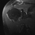
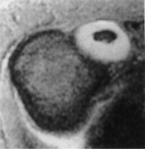 Figure 6.7 Biceps tenosynovitis. Axial gradient-echo T2*-weighted MR image of the shoulder demonstrates a large amount of fluid within the synovial reflection of the biceps tendon that is out of proportion to the fluid seen in the joint. This is consistent with the diagnosis of tenosynovitis. |
Biceps tenosynovitis can be treated conservatively or with aspiration and injection of medications such as anesthetizing agents and steroids. Tenodesis is performed when pain persists.
Tendinosis
Inflammation and degeneration of the tendon result in tendinosis. This is a condition that can be seen in all age groups. Patients report pain over the anterior aspect of the shoulder. It may be localized to the intertubercular groove or radiate caudal or cephalad to it. The pain is usually gradual in onset. The long head of the biceps tendon may be impinged when it courses in the region of the critical zone under the supraspinatus tendon. Although impingement syndromes are discussed in greater detail in Chapter 4, an imaging sign that could support biceps impingement or friction syndromes may
include bone marrow edema about the intertubercular sulcus as well as changes within the tendon proper (Fig. 6.8). The latter may be manifested by tenosynovitis and tendinosis. Chronic tendinosis can lead to rupture of the tendon. A history of acute trauma or overuse of the shoulder is less common.
include bone marrow edema about the intertubercular sulcus as well as changes within the tendon proper (Fig. 6.8). The latter may be manifested by tenosynovitis and tendinosis. Chronic tendinosis can lead to rupture of the tendon. A history of acute trauma or overuse of the shoulder is less common.
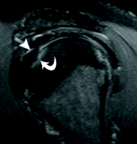 Figure 6.8 Biceps tendon impingement. Sagittal intermediate-weighted fat-suppressed MR image shows intrinsic intermediate signal within the biceps tendon (arrowhead) consistent with tendinosis as well as bone marrow edema (curved arrow) at the superior extent of the lesser tuberosity at the junction of the intra- and extra-articular biceps tendon. These imaging findings support the clinical diagnosis of biceps tendon impingement. |
Microscopically, the tendon may demonstrate increased vascularity, hypercellularity, and fibrosis. The severity of tendinosis is related to its duration and the age of the patient (16). Tendinosis can lead to adhesive capsulitis and tendon rupture.
The diagnosis of tendinosis, and its distinction from partial tears of the tendon is made through analysis of the signal intensity and morphology of the biceps tendon. Intrinsic high signal intensity within the tendon on T1-weighted MR images without brightening to the degree of simple fluid on T2-weighted MR images is characteristic of tendinosis (Fig. 6.9). With regard to morphology, the alteration encountered may parallel the chronicity of the process. In earlier stages of tendinosis, the tendon may have an enlarged appearance. When isolated to the intracapsular portion of the tendon and when severe in nature, this process has been termed the hourglass biceps tendon (Fig. 6.10). This hypertrophy of the intracapsular biceps tendon leads to its incarceration within the joint, inhibiting passive and active elevation and causing pain. In Boileau et al.’s (17) series of 21 patients, the mean diameter of the intracapsular biceps measured 12 mm ± 3 mm, whereas the component within the intertubercular sulcus measured 6 mm ± 2 mm. In the later stages of tendinosis, an attenuated appearance may predominate; the latter has been referred to as attritional tendinosis.
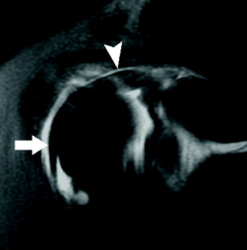 Figure 6.9 Biceps tendinosis. Coronal intermediate-weighted fat-suppressed MR image through the anterior aspect of the shoulder shows a caliber change in the biceps tendon with thickening of the intra-articular (arrowhead) portion versus normal-appearing morphology (arrow) in the intertubercular sulcus. |
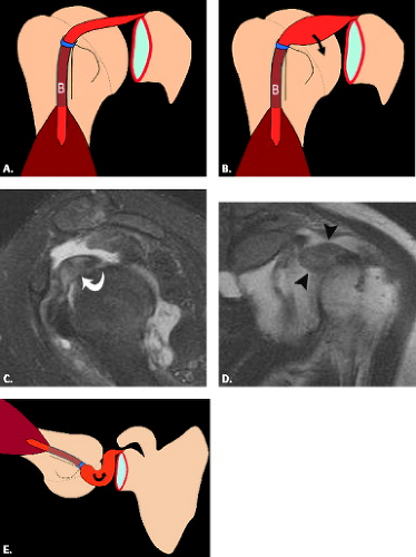 Figure 6.10 Hourglass biceps tendon. Diagram shows normal (A) and the hourglass biceps tendon (B). Sagittal T1-weighted fat-suppressed MR arthrogram image (C) profiles the massively enlarged biceps tendon (curved arrow). Coronal T1-weighted MR arthrogram image (D) through the anterior aspect of the shoulder emphasizes the mass-like enlargement of the intra-articular biceps (arrowheads). Diagram (E) shows the appearance of the hourglass biceps tendon in the abducted and externally rotated position. |
As previously discussed, the magic angle phenomenon may affect the biceps tendon as it goes from the intra-articular region into the bicipital groove, a region that lies approximately 55 degrees to the static magnetic field on short TE images. This appearance can simulate mild tendinosis. This is also a common location for impingement. Because this location is a frequent site of
magic angle phenomenon and if there is a lack of increased signal intensity on T2-weighted MR images, the clinician may put the magic angle phenomenon as the top possibility when describing this appearance.
magic angle phenomenon and if there is a lack of increased signal intensity on T2-weighted MR images, the clinician may put the magic angle phenomenon as the top possibility when describing this appearance.
Partial- and Full-thickness Tears
Partial tears of the long head of the biceps tendon were first described in 1934 by Gilcrest (18) and, along with a variety of other pathologic lesions affecting this structure, was included in the term “common bicipital syndrome.” Pathology of the proximal portion of the biceps tendon is often associated with subacromial impingement and rotator cuff tears, rendering the clinical presentation and physical examination findings nonspecific (19). Partial-thickness tears may present as thinning, irregularity, fragmentation, or increased signal intensity on MR images (Fig. 6.11). Longitudinal fissures and splits of the tendon are commonly encountered types of partial tears (Fig. 6.12). This is most common superiorly. A bifid biceps tendon can be mistaken for a longitudinal split of the biceps tendon. The distinction from a tear can be difficult but is more likely if the bifid tendon is seen on all axial MR images and extends into the glenohumeral joint toward the attachment on the supraglenoid tubercle. The labral attachment should also appear intact to distinguish from a superior labral anterior–posterior (SLAP) lesion associated with a longitudinal biceps tendon tear.
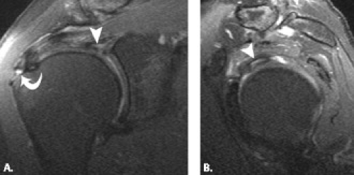 Figure 6.11 Partial tear of intra-articular biceps tendon. Coronal (A) and sagittal (B) intermediate-weighted fat-suppressed MR images through the shoulder show bright signal within the substance of the intra-articular biceps tendon (arrowhead) consistent with a partial tear. On the coronal (A) image, incidental note is made of a low-grade bursal-sided tear of the supraspinatus tendon (curved arrow) superimposed on a background of tendinosis. |
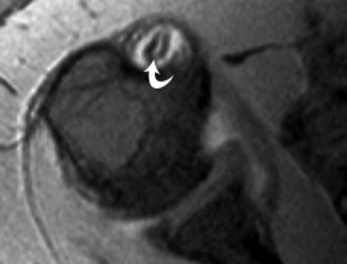 Figure 6.12 Partial tear of the intertubercular sulcus biceps tendon. Axial gradient-echo MR arthrogram image shows contrast extending into a longitudinal split tear of the biceps tendon (curved arrow). |
Most tears of the long head of the biceps tendon occur at the proximal portion of the bicipital groove, usually in patients older than age 40 years. Less commonly, complete failure occurs just proximal to the bicipital groove and rarely at the biceps labral junction.
Musculotendinous ruptures are infrequent and are usually associated with significant trauma. In general, the region of failure occurs at a site of pre-existing tendinosis. Full-thickness ruptures have been reported in bodybuilders and weight lifters (20). As a result of the robust tensile strength of the normal biceps tendon, acute rupture of the healthy tendon is a rare occurrence and requires extreme circumstances.
Musculotendinous ruptures are infrequent and are usually associated with significant trauma. In general, the region of failure occurs at a site of pre-existing tendinosis. Full-thickness ruptures have been reported in bodybuilders and weight lifters (20). As a result of the robust tensile strength of the normal biceps tendon, acute rupture of the healthy tendon is a rare occurrence and requires extreme circumstances.
Neer (21) has stated that biceps tendon ruptures are extremely uncommon without coexisting rotator cuff abnormalities and has classified full-thickness tears of the long head of the biceps tendon into three types. Type 1 is a tear without retraction; type 2 is a tear with partial retraction; and type 3 is a self-attaching tear without retraction. This latter type of tear can be difficult to diagnose clinically and MRI can be of help in this situation. Some clinicians have found it difficult to distinguish fibrous tissue in the bicipital groove from the bicipital tendon itself. In the acute setting, however, patients often report hearing a “pop” and identifying a subsequent deformity of the arm resulting from the distal displacement of the torn extracapsular biceps tendon and contracted
muscle. This appearance has been referred to as the “Popeye” sign.
muscle. This appearance has been referred to as the “Popeye” sign.
MRI allows direct visualization of the biceps tendon rupture and is evidenced by tendon discontinuity. The identification of the location of the rupture and ultimate location of the torn ends of the tendon should be described. When there is distal retraction of the muscle, there is absence of the tendon in all or a portion of the bicipital groove. When the failure occurs at the proximal aspect of the intertubercular sulcus, the stump of the torn proximal biceps tendon can be difficult to identify and often displaces anteriorly into the region of the rotator cuff interval capsule (Fig. 6.13). In addition, a retained biceps tendon stump at the superior glenoid from a tear can cause glenoid and humeral head chondromalacia through a “windshield wiper” mechanism and it is important to remove it before this occurs (22).
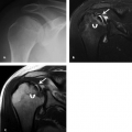
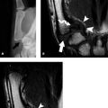
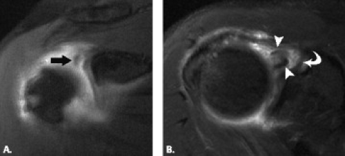 Figure 6.13 Complete rupture of biceps tendon with free stump. Coronal (A) intermediate-weighted fat-suppressed MR image shows the anteriorly displaced torn proximal biceps tendon (arrow). Axial (B) T2-weighted fat-suppressed MR image profiles the torn proximal biceps tendon (arrowheads) that is anteriorly displaced and residing anterior to the superior glenohumeral ligament (curved arrow). |
Subluxation and Dislocation
In the past, it was believed that medial subluxation of the biceps tendon could occur in an isolated fashion. As a result of extensive research and consideration of the many stabilizers and complex anatomy of the biceps tendon, it is fairly well accepted that the primary medial stabilizers of the biceps include the constituents of the biceps tendon pulley (superior glenohumeral and coracohumeral ligaments) and the subscapularis tendon. Moreover, for biceps subluxation to occur, one of these two stabilizers must be insufficient and for biceps tendon dislocation to occur, both stabilizers must be disrupted. A dislocated biceps tendon is defined as a tendon that has no contact with the bicipital groove, whereas a subluxed biceps tendon retains some contact with the groove. By far, the most common direction of tendon displacement is medial. Posterior dislocation of the biceps tendon has been described in the setting of trauma as has been incarceration of the biceps into the joint with both entities being extremely rare in nature (Fig. 6.14) (23, 24).
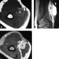
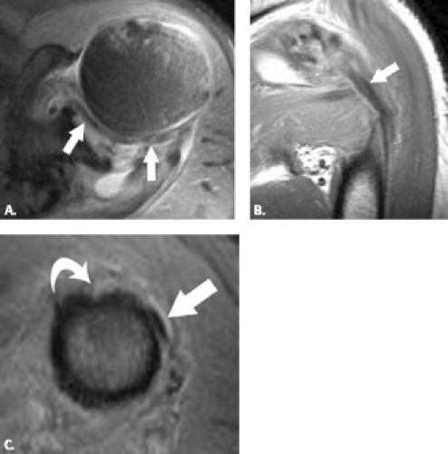 Figure 6.14 Posterior dislocation of the biceps tendon. Axial (A) proton density-weighted fat-suppressed MR image in a trauma patient shows incarceration of the biceps (arrows) and within the joint as it courses posteriorly. Coronal (B) proton density-weighted MR image shows posterior displacement of the biceps tendon (arrow). Axial (C) proton density-weighted MR image at the proximal humeral shaft shows the biceps (arrow) coursing from a posterior position toward the intertubercular sulcus (curved arrow). |
The clinical presentation of biceps tendon dislocation and rotator cuff tear can be similar and an accurate diagnosis is important. The patient may experience snapping of the tendon and there are several provocative tests that have been used to diagnose this disorder (25, 26).
Several classification systems have been introduced to describe instability patterns of the biceps tendon (27, 28). One recent description classified biceps instability in the setting of patients who underwent arthroscopy for rotator cuff pathology. In this study, biceps instability was discovered in 45% of patient with both directional subluxations (isolated posterior encountered in 19% of patients, isolated anterior in 16%, and combined in 10%) as well as complete dislocations (29). The modification of a system introduced by Habermeyer et al. presents an organized and intuitive approach to this complex process that includes six patterns of tendon
instability that are divided into three separate categories and are based on an understanding of the normal anatomic relationship of the structures of the biceps pulley and rotator cuff tendon attachments about the intertubercular sulcus (Fig. 6.15) (30, 31). These categories include: (i) tendon displacement or subluxation, (ii) extra-articular dislocation, and (iii) intra-articular dislocation. The first type has been described as tendon displacement with an isolated subscapularis tendon tear. A partial intrasubstance or articular-sided tear of the tendon can allow a very minimal medial shift of the intact biceps tendon and pulley structures. The second type of
pathology includes tendon subluxation with a tear of the medial limbs of the biceps pulley (coracohumeral and superior glenohumeral ligaments) and an intact subscapularis. The biceps tendon subluxes medially through the torn pulley but is restrained from further medial subluxation by an intact subscapularis tendon (Fig. 6.16
Related posts:
Stay updated, free articles. Join our Telegram channel
Full access? Get Clinical Tree
