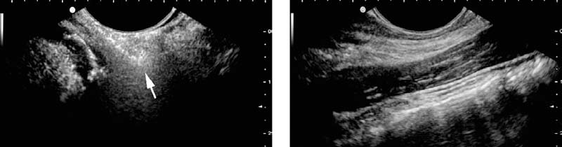
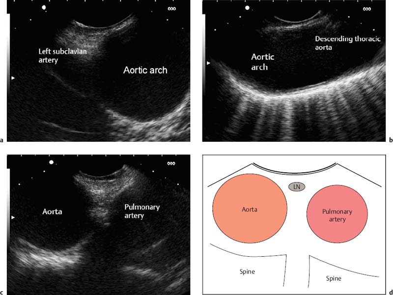
2 Longitudinal EUS Anatomy Endoscopic ultrasonography (EUS) started in the 1980s with mechanical radial scanners, which provide a circumferential overview of the gastrointestinal wall and surrounding structures. This specific imaging method was quickly accepted, and reports about difficult anatomic orientation were rare—probably due to the resemblance of the images to those provided by computed tomography (CT). Some 10years later, longitudinal electronic scanners were developed, allowing biopsies to be taken and EUS interventions to be performed with real-time guidance. Despite the high resolution and good image quality provided, these systems had, and are still having, difficulty in becoming accepted as routine diagnostic instruments as well. The main obstacle is the impression that anatomic orientation is more difficult, resulting in a longer learning curve. The image produced with linear EUS is similar to that in conventional ultrasound images. To make it easier to recognize images familiar from abdominal ultrasound, the image orientation on the monitor should be analogous: oral (= cranial) on the left side of the screen and anal (= caudal) on the right side. The lack of a circumferential view has to be compensated by 360° rotation with the echoendoscope. Skilled ultrasonographers and endoscopists, including those with experience in endoscopic retrograde cholangiopancreatography (ERCP), are therefore likely to succeed more easily with linear EUS. Since the very beginnings of longitudinal EUS, several groups have been concerned with the issues involved in education and training in EUS.1–4 Workshops and meetings provide an opportunity to learn the examination technique, as well as useful tricks, from experts. However, hands-on training requires a familiar setting and cannot be offered in workshops. When various EUS centers are compared, it is surprising to see how many different approaches to linear EUS there are, each represented by successful experts. The technique presented in this chapter thus describes only one of several ways of performing linear EUS. The Philosophy of the Examination The underlying idea is to develop EUS anatomy along landmarks and guiding structures. The need for endoscopic control is negligible; the exact position of the tip of the echoendoscope is of no interest. Introduction of the Echoendoscope As the tip of a longitudinal echoendoscope is stiff and relatively long, it might be difficult to insert the scope smoothly into the esophagus. In particular, the insertion of thicker therapeutic instruments might be challenging. After testing different approaches, the following EUS-guided procedure has proven to be most successful in our institution:Outside the patient, the tip of the scope is rectangularly deflected and inserted around the root of the tongue into the hypopharynx. From this moment, the wall of the hypopharynx can be visualized endosonographically. Often the wall is folded and the tip of the scope could violate or even penetrate the wall when being pushed forward (Fig. 2.1a). By slight rotation of the probe, the dorsal wall can be coupled on parallel with the scanner and is displayed horizontally (Fig. 2.1b). The scope can now easily be moved forward into the esophagus. Any force must be avoided to prevent perforation. The long axis in the chest and abdomen is represented by the thoracic and abdominal aorta, which can be imaged from the esophagus and stomach. The pancreas is the transverse axis in the abdomen. The third guiding structure (which is of lesser importance) is the inferior vena cava (IVC), which can be imaged from the descending part of the duodenum. Fig. 2.1a, b The deflected tip of the echoendoscope is introduced into the hypopharynx, but the wall layers cannot be identified due to folds and interposed gas (arrow) (a). After slight rotation of the tip toward the dorsal wall and partial reversion of the deflection, the wall layers can be displayed horizontally (b). The probe can now easily be moved into the esophagus. As the aorta is used as the main longitudinal anatomic axis, it seems reasonable to pick up this structure as early as possible while introducing the scope. As the aorta is followed, further anatomic structures become visible, as described in detail later. Thus, the examination starts orally and subsequently extends to the aboral areas. Usually, the region of interest is imaged repeatedly, with the instrument being moved forward and backward while the scope is rotated, as appropriate. Until the pylorus has to be passed, there is normally no need for endoscopic guidance, except to examine small mural lesions. Air insufflation is therefore not necessary, and close contact between the probe and the gastrointestinal wall is established more easily. Deep introduction of the echoendoscope into the duodenum is not required for several EUS indications, such as the staging of esophageal cancer. Intubation of the duodenum is necessary to visualize the anatomic area around the pancreatic head or common bile duct, or both. After the echoendoscope has been introduced, the first anatomic structure seen is the aortic arch, at ≈ 22 cm from the incisors. The branching of the left subclavian artery can be detected immediately, or after turning the scope slightly to the left (Fig. 2.2a). Continuing the rotation in a counterclockwise direction along the aortic arch leads to the descending thoracic aorta (Fig. 2.2b), which can easily be followed caudally by pushing the scope and adjusting the wheels to adapt the probe to the longitudinal axis of the aorta ( The aortopulmonary window, covering level 4 L lymph nodes according to the American Thoracic Society (ATS) map, can also be depicted starting at the aortic arch, with the instrument now being rotated clockwise and moved slightly forward (Fig. 2.2c, The trachea is found ≈ 18–25 cm from the incisors by rotating the probe to the front (≈ 180° when starting from the descending aorta). It is sonographically characterized by a bright line with dorsal reverberating artifacts, which are caused by the intratracheal air (Fig. 2.3a, Fig. 2.2a–d a The aortic arch and left subclavian artery are seen at 22 cm from the incisors. b When the scope is turned counterclockwise, the arch can be followed into the descending thoracic aorta. c When the instrument is rotated clockwise and pushed slightly, the aortopulmonary window becomes visible. d The anatomic outline of the aortopulmonary window. LN: level 4L lymph node (American Thoracic Society map).
 Whenever the echoendoscope cannot be moved easily, endoscopic guidance is mandatory to avoid injuring or even perforating the gastrointestinal wall.
 EUS Anatomy Displayed from the Esophagus
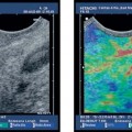
![]() Video 2.1a).
Video 2.1a).
 Video 2.1c). Figure 2.2d is a diagram illustrating the aortopulmonary window.
 Video 2.2). As the scope is moved forward, the line will end at the carina of the trachea (
 Video 2.2). The infracarinal area is the region of the posterior level 7 lymph nodes according to the ATS map, which is easily accessible for EUS-guided puncture. For visualization of the right main bronchus, the instrument has to be rotated clockwise (Fig. 2.3b). For the left main bronchus, the imaging procedure is reversed. Figure 2.3c is a diagram illustrating the trachea and infracarinal lymph node stations.
 If one scans to the front (e.g., trachea/bronchi), the scope has to be rotated equivocally
Related posts:
![]()
Stay updated, free articles. Join our Telegram channel

Full access? Get Clinical Tree


Radiology Key
Fastest Radiology Insight Engine