Magnetic resonance imaging (MRI) offers infinite gray scale resolution allowing for improved tissue characterization and multiplanar capabilities. This facilitates the diagnosis of a variety of benign and malignant conditions involving the female pelvis without the use of ionizing radiation. Common indications for MRI of the pelvis are pain, infertility, adnexal mass characterization, incontinence, and cancer staging, including assessment of posttherapeutic response and complications. There is increasing use of MRI for the evaluation of congenital anomalies, lymphadenopathy, and pain in pregnant patients during the second and third trimesters. The goal of this chapter is to provide an overview of basic MRI techniques and normal gynecologic anatomy, illustrative conditions, and common pitfalls.
Technical Requirements
Ideally, scanners with field strengths of at least 1.0 Tesla should be used to perform a diagnostic pelvic MRI study. Current standard of care for pelvic MRI includes the use of a multicoil array ( Figure 5-1 ), which increases signal-to-noise ratio and provides better anatomic resolution. The multicoil array consists of several adjacent receiver coils arranged in a belt, which when secured around the pelvis act as individually separate receivers of signal transmitted from the pelvic organs. The signals are acquired simultaneously with spatially encoded information, which are then summed before processing into an image. This improved signal acquisition allows for decreased scan time and improved image resolution compared with use of a standard whole-body magnet alone.

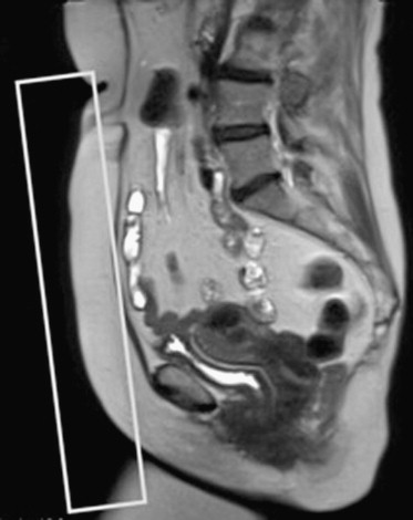
Limitations in the use of multicoil array include misregistration artifact along the phase encoding direction, which is introduced by respiratory motion particularly when not properly secured or when applied over clothing. In some instances, compression bands may be used to minimize abdominal wall motion. Near-field bright artifact ( Figure 5-2 ) occurs with large amounts of subcutaneous fat, which accentuates motion artifact. This can be reduced by the application of saturation bands (5 cm in thickness) along the anterior abdominal wall fat with the position determined by the sagittal scout image ( Figure 5-3 ). The time required to add these bands precludes the use of ultrafast sequences, such as T2-weighted half-Fourier rapid acquisition with relaxation enhancement (RARE). Because signal-to-noise ratio is inversely related to the radius of the individual coils, images acquired from obese or pregnant patients and those with large pelvic masses extending into the abdomen demonstrate signal loss centrally. These patients are better imaged directly using the whole-body resonator alone ( Figure 5-4 ). A summary of common artifacts and remedies is presented in Table 5-1 .


| Artifacts | Cause | Remedy |
|---|---|---|
| Double-contour artifact and blurring | Motion (breathing, peristalsis, movement during examination) | Fast imaging, properly secured multicoil array, respiratory coaching, compression bands, proper fasting and voiding, saturation bands, and fat suppression |
| Near-field bright artifacts | Large amount of subcutaneous fat | Saturation bands, fat suppression |
| Loss of signal in center of field of view | Obesity, large masses, pregnancy or ascites, high magnet strength (3 Tesla) | Image directly with body coil |
| Nonuniform fat saturation | Magnetic field inhomogeneity | Optimization of field homogeneity, center anatomy within bore |
| Magnetic susceptibility artifact | Metal implants | Use of spin echo sequence with 180-degree refocusing RF pulse, TSE with long echo trains |
| Truncation artifacts | Large amount of subcutaneous fat | Fat suppression or inversion recovery |
| False bladder wall thickening | Chemical shift | Change in direction of frequency encoding gradient, fat suppression |
Endorectal and endovaginal coils ( Figure 5-5 ) are used for higher resolution of the rectum, vagina, urethra, and periurethral anatomy. Both an endovaginal (Phillips, Andover, MA) and an endorectal coil (Siemens, Malvern, PA) are commercially available. Similar to the multicoil array coil, these coils operate as a receiver of signal from surrounding pelvic tissue before information is processed into an image. A disadvantage in the use of endoluminal coils is the limited field of view, where often the entire uterus cannot be seen or large pelvic masses are incompletely evaluated. These coils can be combined with the use of a multicoil array to obtain higher-resolution images of both the luminal structure and the adjacent pelvic organs. In general radiology practice, the most common use of the combined coils is for evaluation of the prostate gland.

Patient Preparation
A thorough gynecologic history, including the presence of pelvic devices and foreign bodies, should be obtained. Intrauterine devices ( Figure 5-6 ) and sterilization clips can safely go into the magnet with acceptable minimal artifact produced. Artificial joints are also safe; however, these result in more significant artifacts, particularly of the pelvic floor. As is true for all other MRI scans, nontitanium aneurysm clips, metal near the optic nerve, pacemakers, implantable defibrillators, and cochlear implants remain contraindications to MRI ( Box 5-1 ).

- ▪
Cardiac pacemakers and defibrillators
- ▪
Nontitanium aneurysm clips
- ▪
Drug infusion pumps
- ▪
Implantable defibrillators
- ▪
Implanted electronic stimulators
- ▪
Cochlear implants
- ▪
Metal near the optic nerve
Patients should be requested to fast for 6 hours before imaging to minimize motion artifact from intestinal peristalsis. The use of glucagon has fallen out of favor because of increased cost and occasional paradoxical patient reactions. In recent years, its benefit has been further reduced as a result of improvement in scanning speeds, rendering image acquisition less motion sensitive. Voiding within 30 minutes before scanning is advised to minimize anatomic distortion artifacts related to bladder peristalsis and patient movement caused by discomfort. Compression bands can be used to decrease artifact related to bowel motion and respiration, although the latter is less problematic in imaging of the pelvis. Gastrointestinal contrast agents are not routinely used for pelvic examinations. Although some centers advocate the use of vaginal or rectal gels to help characterize surface abnormalities such as in endometriosis, this is not necessary for most examinations. Tampons are not used to evaluate the vaginal canal and can often alter the normal anatomy and be mistaken for pathology.
Because scans may last as long as 30 to 45 minutes, the patient is positioned supine, with legs supported under a bolster, to make the examination more comfortable. Earplugs are provided to the patient to help minimize noise related to some sequences.
Pulse Sequences and Imaging Planes
Correlating the various appearances of tissues on T1- and T2-weighted images, before and after contrast images, and without and with fat suppression allows for the evaluation of pelvic anatomy and disease. T2-weighted images best demonstrate the internal anatomy of pelvic organs because of inherent differences in the water content of various tissue types, and are helpful in assessing for pathology depicted by relative increase in water content. This aids in the evaluation of cystic masses, free fluid, inflammation, necrosis, and fistulas. Because fat is bright on T1- and T2-weighted images, fat suppression is useful to make fluid more conspicuous. Compared with T2-weighted images, T1-weighted images are not as useful for the demonstration of the internal anatomy of the pelvic organs, but are excellent for definition of anatomic boundaries between soft tissues and fat planes, which are intermediate to dark and bright in signal, respectively. Fat suppression and in-phase and out-of-phase imaging techniques are useful in identifying certain fat-containing pelvic pathologies such as dermoids and differentiating them from hemorrhage-containing structures such as hemorrhagic cysts or endometriomas ( Figures 5-7 and 5-8 ). Certain pelvic disease states involving increased fluid such as necrosis and cystic and phlegmonous changes are low in signal, which become more identifiable in the background of bright fat. Calcifications are low in signal in both T1- and T2-weighted imaging, and fibrosis is intermediate on T1-weighted imaging and low on T2-weighted imaging.


Intravenous gadolinium-based contrast shortens T1, rendering vascular structures, inflammation, and neovascularity higher in signal. The timing of dynamic images helps to further characterize disease—specifically whether they are hypervascular, late enhancing, or non enhancing, suggesting angiogenesis, fibrosis, or necrosis, respectively. T2-weighted images are more helpful to characterize pelvic anatomy compared with postcontrast T1-weighted images. When intravenous contrast is used, however, fat saturation is used to improve conspicuity of enhancement in the darker background of suppressed fat ( Figure 5-9) .

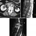
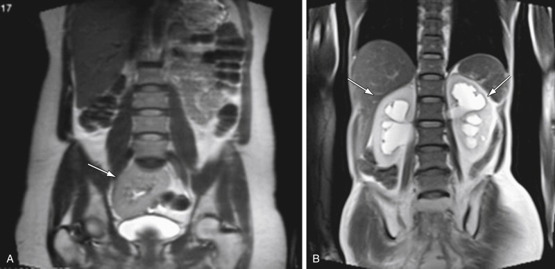
The first images of a study include a localizer sequence consisting of rapidly acquired coronal, sagittal, and axial T2-weighted images of the entire abdomen and pelvis. This is obtained to optimize positioning of the multicoil array over the area of interest. It is imperative that the array be positioned so that the anterior and posterior coils are at the same level. The large field of view of the initial scout also allows for cursory assessment of the kidneys and uterus, and detection of urinary tract obstruction ( Figure 5-10 ). The sagittal scout image is used to assess the position of the uterus, check for proper placement of endocavity coils, and for strategic positioning of the presaturation bands over the anterior and posterior abdominal adipose tissue. Finally, evaluation of the three planes allows for optimal planning of the subsequent smaller field-of-view series.
Multiplanar T2-weighted images are then obtained to provide excellent contrast resolution for the depiction of the uterine, ovarian, and cervix zonal anatomy, fluid-filled structures present in the female pelvis and free fluid. Because T2-weighted images are superior compared with the majority of other pulse sequences in depicting anatomic features and pathology in the female pelvis, sagittal and axial T2-weighted images should be obtained early in the examination when patient cooperation is optimal. Either free-breathing RARE or rapid breath-hold, such as half-acquisition RARE, sequences may be used. T2-weighted RARE images yield the highest spatial resolution but require approximately 3 minutes to obtain. Because the axial images are of paramount importance, T2-weighted RARE images should be obtained in this plane. In cooperative patients, rapid breath-hold sagittal and coronal T2-weighted sequences, using half-acquisition RARE, yield high-quality images in less than 25 seconds ( Figure 5-11 , A ). These T2-weighted sequences are often sufficient for benign conditions, such adenomyosis, mullerian anomalies, and in the general evaluation of fibroids. Although customarily used for T1-weighted imaging, fat saturation techniques with T2-weighted images can be used to demonstrate pathology, which is particularly helpful when intravenous contrast cannot be used. Fat signal can be nulled by using short time inversion recovery (STIR) or spectral adiabatic inversion recovery techniques resulting in better depiction of high signal related to inflammation or fluid ( Figure 5-11 , B ). The latter technique more selectively suppresses the fat signal and is less sensitive to motion, resulting in a better signal-to-noise ratio. High-resolution images may also be obtained using isotropic fat-saturated proton density–weighted three-dimensional (3D)-RARE sequences with a 3-Tesla magnet ( Figure 5-11 , C ). Because the pelvis is less affected by motion related to diaphragmatic motion compared with imaging of the abdomen, free-breathing sequences are often sufficient, especially with the use of saturation bands.

Similar to T2-weighted sequences, T1-weighted image acquisition may be tailored according to the level of patient cooperation. As a result of repeated imaging, spin-echo sequences provide the highest resolution with free breathing but also require longer acquisition times. In cooperative patients the shorter time-requiring RARE pulse sequences provide good images. Slices are obtained with a single breath-hold, allowing limited coverage and repeated imaging. Both techniques can be combined with fat suppression. Shorter scan times are possible using two-dimensional (2D) spoiled gradient echo sequences, which also allow performance of in- and opposed-phase imaging. Adding an inversion pulse before the T1 gradient echo sequence increases the signal-to-noise ratio.
T1-weighted 3D gradient echo images yield thin-slice images usually 3.0 to 3.5 mm in thickness, allowing for thinner slice interpolation and vascular reconstructions. Although this sequence provides a lower signal-to-noise ratio compared with the previously described T1 sequences, the diagnostic information obtained after intravenous administration of gadolinium-based contrast agents (0.1 mg/kg body weight) is critical for the assessment of adnexal masses and staging of cancer. With gradient echo sequences, additional diagnostic information may be obtained by in-phase and out-of-phase imaging characterizing tissue with intravoxel water and fat (see Figure 5-8 ).
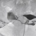
Contrast agents, usually gadolinium chelates, are best administered using a power injector at a rate of 2 mL/s followed by a saline flush. Arterial phase images are obtained using one of several techniques. A simple method uses a standard time of 25 seconds after injection to begin imaging. Patient variables such as cardiovascular status, weight, location, and size of intravenous catheter may affect the rate of arterial enhancement. A more customized strategy uses a test bolus of 2 mL of intravenous contrast hand injected at 2 mL/s. Region-of-interest monitoring above the aortic bifurcation is performed, which generates a time-density curve optimizing timing for the main bolus administered using a power injector. Most scanners are also equipped with a bolus tracking system that will automatically begin acquisition when the contrast bolus reaches the region of interest. Once the optimal delay time is determined, images are usually obtained during a breath-hold of approximately 15 to 20 seconds. Verbal or visual cues should be given to the patient to diminish breathing artifact. In healthy patients, optimal contrast between tumor and myometrium occurs between 2 and 3 minutes, and maximal endocervical mucosa enhancement occurs between 4 and 5 minutes. In most clinical cases, arterial phase images are obtained followed by delayed images performed 60 and 120 seconds from the time of injection. Data from the arterial phase scans can be used to reconstruct angiograms ( Figure 5-12 , A ) for either arterial embolization evaluation or surgical planning for tumor removal. Venograms can also be reconstructed ( Figure 5-12 , B ).

Evaluation of vascular anatomy may also be performed without the use of intravenous contrast, measuring the motion of blood to visualize either arterial or venous flow. More commonly used techniques are the time-of-flight and phase-contrast magnetic resonance angiography techniques. As with contrast-enhanced magnetic resonance angiography, data obtained can be used to reconstruct maximum intensity projection models. Compared with contrast-enhanced magnetic resonance angiography, these noncontrast techniques are more sensitive to flow-related artifacts.
For detailed evaluation of small structures such as the vagina or urethra, small field-of-view images using high-resolution fast spin echo sequences are obtained. In evaluating fetal anomalies, multiplanar half-acquisition RARE or similar sequences with large fields of view are obtained, yielding snapshot images of the fetus.
The standard imaging planes used for imaging the pelvis are axial, sagittal, and coronal. As mentioned previously, large field-of-view coronal T2-weighted images are used as a scout image, along with the midsagittal scout view to be used as a guide for the application of saturation bands. The anatomy of the uterus and ovaries is best demonstrated in the axial plane. This plane is particularly important in the assessment of the parametrium and in the identification of pelvic lymphadenopathy. Therefore because the axial plane is most critical for diagnosis, it should be obtained first, especially in a patient who may tire easily or be uncooperative. For greater anatomic detail, the plane of acquisition may be adjusted along the long axis of the organ of interest based on the midsagittal scout.
The sagittal plane best depicts the zonal anatomy and position of the uterus and cervix. Anatomic relationships between pelvic compartment organs, particularly when tumor extension is being evaluated, are well demonstrated on this imaging plane. The coronal plane is complementary to the other planes and is particularly important in the assessment of pelvic lymphadenopathy ( Figure 5-13 ) and adnexal structures. A summary of optimal scanning planes is provided in Table 5-2 . A standard imaging protocol for the pelvis is provided in Table 5-3 .

| Sagittal | Uterus and cervix position, endometrium thickness, pelvic floor and relationship of pelvic compartment structures, cul-de-sac, presacral space |
| Coronal | Pelvic floor, uterine developmental anomalies, lymphadenopathy, adnexae |
| Axial | Lymphadenopathy, parametrium, vagina, cervix, uterus, ovaries |
| Organoaxial | Detailed evaluation of uterus, cervix, or vagina, parametrium |
| Precontrast Sequences | ||||||||||
|---|---|---|---|---|---|---|---|---|---|---|
| Sequence | TR (ms) | TE (ms) | Fat Saturation | Acquisition Time (sec) | Field of View (mm) | Thickness (mm) | Flip Angle (degrees) | Frequency Matrix | Phase Matrix | |
| Coronal | Half-acquired RARE | 1500 | 90 | 45 | 375 | 7 | 170 | 256 | 80% | |
| Sagittal | Half-acquired RARE | 1500 | 90 | 45 | 350 | 7 | 170 | 256 | 256 | |
| Axial | T2 RARE (high resolution) | <800 | Min (~10 ms) | 300 | 250 | 4 | 180 | 320 | 80% | |
| Axial | 2D GRE | 175 | 40 | 360 | 6 | 70 | 320 | 182 | ||
| In phase | 2.33 | |||||||||
| 2D GRE out of phase | 4.66 | |||||||||
| Axial | 3D GRE | Min | Min | Fat suppression or inversion recovery | <20 | 360 | 2.5 | 10 | 256 | 160 |
| Postcontrast Sequences | ||||||||||
| Plane | Sequence | TR (ms) | TE (ms) | Fat Saturation | Acquisition Time (sec) | Field of View (mm) | Thickness (mm) | Flip Angle (degrees) | Frequency Matrix | Phase Matrix |
| Axial | 3D GRE | Min | Min | Fat suppression or inversion recovery | <20 | 360 | 2.5 | 10 | 256 | 160 |
| Optional Sequence | ||||||||||
| Plane | Sequence | TR (ms) | TE (ms) | Fat Saturation | Acquisition Time (sec) | Field of View (mm) | Thickness (mm) | Flip Angle (degrees) | Frequency Matrix | Phase Matrix |
| Axial | 3D T2 RARE | 1200 | 120 | 390 | 256 | 1.0-1.5 | 180 | 256 | 256 | |
Normal Anatomy, Magnetic Resonance Imaging Appearances, and Common Differential Considerations
Vagina
Anatomy
The vagina, derived from the Latin word meaning sheath , is a fibromuscular canal approximately 10 cm long, which extends from the cervix to the vulva. With its functions as a copulatory organ, outlet for menstruation, and birthing canal, it is composed mainly of thin layers of muscle and elastic tissue. It consists of an inner mucosal layer composed of nonkeratinized stratified squamous epithelium, an intermediate muscular layer with a bihelical arrangement of fibers, and an outer adventitial layer known as the paravaginal fascia, containing both dense and loose connective tissue and rich in blood vessels and nerves. Because of its pliable nature, its morphology is influenced both by its supporting ligaments and neighboring structures. Wider in the transverse plane, its anterior and posterior walls are approximated by the urinary bladder and urethra anteriorly and by the rectum posteriorly. With the impressions of these organs, along with the lateral wall support provided by the arcus tendineus, the lumen of the vagina assumes a butterfly or H configuration in the axial plane throughout most of its length. The uppermost aspect of the anterior vaginal wall is formed by the cervix, making it shorter than the posterior wall by approximately 3 cm. Reflections of the vaginal wall surrounding the outer cervix form the anterior, posterior, and the lateral fornices, which later form the upper margins of the lateral sulci. The cardinal and uterosacral ligaments along with the endopelvic fascia that support the cervix also provide support for the upper vagina. More inferiorly the vagina becomes constricted at the introitus, where it is fused with the urethra anteriorly and the perineal body posteriorly. The lateral support is provided by the fibers of Luschka of the pubococcygeus of the levator ani muscle group. Only the posterior vaginal fornix is covered by serosa, forming part of the cul-de-sac. The remainder of the organ is surrounded by fatty connective tissue called the paravaginal fascia. This richly vascularized connective tissue extends anteriorly to surround the urethra. Destruction of this fascia is associated with urinary incontinence.
The vagina is supplied by a rich network of vessels primarily from the descending branch of the uterine artery and branches of the internal iliac arteries, including the vaginal, rectal, vesical, and pudendal arteries. These branch vessels traverse its lateral wall and anastomose at the midline to supply the anterior and posterior vaginal walls. The pudendal artery provides branches to the inferior vagina. The posterior vaginal wall is also partly perfused from hemorrhoidal branches. The distal vagina is drained by the inguinal and anorectal lymph nodes, whereas the middle and upper third vagina drains into the paraaortic, internal and external iliac, sacral, and obturator group of lymph nodes.
Imaging Appearances
The vaginal canal is best evaluated using T2-weighted images in the axial plane, depicting its zonal anatomy and relationship to adjacent structures, including the paravaginal fascia. On T2-weighted images ( Figure 5-14 , A ), the low signal muscular layer with the closely apposed submucosa is clearly seen between areas of high signal: the mucosal epithelium and mucous secretions centrally, and the richly vascularized adventitia surrounding the vaginal muscular wall. On the axial plane, these layers resemble a butterfly or H-shaped structure. On T1-weighted images, the vagina and adjacent tissues demonstrate intermediate signal and are therefore difficult to separate. After contrast enhancement and with the use of fat saturation, the mucosa and its secretions are low in signal, whereas the more vascular muscularis and adventitia are rendered higher in signal ( Figure 5-14 , B and C ). Sagittal images are useful for demonstrating the anterior and posterior vaginal fornices, as well as the pouch of Douglas, which is formed by the serosa covering the posterior aspect of the upper vagina and the anterior rectal wall ( Figure 5-15 ). The use of an endovaginal or endorectal coil can produce high-resolution images, providing excellent detail of perivaginal anatomy at the expense of a smaller field of view with the potential for patient discomfort.