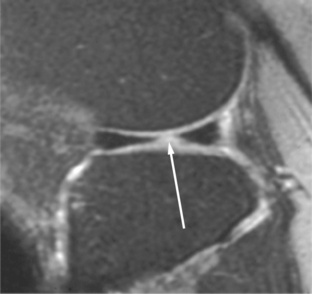
CHAPTER 9 Magnetic resonance imaging (MRI) of the knee has developed into one of the most commonly requested examinations in radiology. This is not just because many people injure their knees but because of its high accuracy in depicting internal derangements. Accuracy reports of MRI scans for the knee vary from 85% to 95%, with many investigators believing that MRI of the knee is, in fact, more accurate than arthroscopy. Very few top orthopedic surgeons will operate on a knee without an MRI scan to serve as a road map. Although some surgeons believe MRI scanning is too expensive for routine use in every patient, there are studies that report enormous financial savings (not to mention decreased patient morbidity) in performing an MRI examination on every patient who is a candidate for knee arthroscopy. Many of these patients do not need subsequent arthroscopy and those who do benefit from a more complete preoperative assessment (not directly reflected in financial savings but clearly beneficial for surgical planning).1 MRI scanning of the knee has a very high negative predictive value; therefore a normal MRI knee examination is highly accurate in excluding an internal derangement.2,3 A few centers continue to use T1-weighted coronal images without realizing that they give no additional information and, in fact, can hide significant abnormalities. Why would they do this? T1-weighted coronal images were part of everyone’s protocol when we first began to use MRI scanning in the knee. Articles, book chapters, and speakers (including me) would give the standard protocol, not thinking enough about what each sequence was showing us. I remember reading a knee study in the late 1980s with one of the radiology residents, and I asked him to hedge on the diagnosis of a partial tear of the medial collateral ligament and request a repeat examination with T2-weighted coronals to rule out a meniscocapsular separation. This was the second or third time that week that the resident had been so instructed, so he asked, “Why don’t we just routinely do a T2 coronal—we don’t see anything on the T1 coronal, and we often have to hedge or repeat the examination with a T2 coronal?” I told him to worry about dictating the cases, and I and others would take care of setting up the protocols. Well, 2 weeks later he rotated to another service, and we began doing T2 coronal images as part of our standard knee protocol. Uppity residents! The use of FSE sequences with a short TE (FSE proton-density) has been reported in several studies to be useful for meniscal tears, yet others have reported a decreased sensitivity. What is the truth? The truth is that every published report I can find shows a sensitivity of around 80% for FSE proton-density sequences, whereas conventional spin-echo sequences have a sensitivity closer to 95%. It is very controversial, but basically everyone’s results are the same (80% sensitivity), only the conclusions differ.4 If you’re willing to decrease your sensitivity for meniscal tears from 95% to 80% to save 3 minutes (the only advantage of FSE), then your time is more valuable than your diagnostic accuracy. Get another job! The protocol I currently recommend consists of a sagittal proton-density weighted spin-echo series with fat suppression and sagittal, coronal, and axial FSE T2 with fat suppression (Table 9-1). Many acceptable variations of this protocol exist. Many centers, for various reasons, prefer not to use FSE images and instead use gradient-echo. The normal meniscus is a fibrocartilaginous, C-shaped structure that is uniformly low in signal on both T1- and T2-weighted sequences (Figure 9-1). With T2* sequences the menisci will usually demonstrate some internal signal. With T1-weighted images any signal within the meniscus is abnormal, except in children, in whom some signal is normal and represents normal vascularity. Meniscal signal that does not disrupt an articular surface is representative of intrasubstance degeneration (Figure 9-2), which is myxoid degeneration of the fibrocartilage. It most likely represents aging and normal wear and tear. It is not believed to be symptomatic and cannot be diagnosed clinically or with arthroscopy. Some choose, therefore, not to mention intrasubstance degeneration in the radiology interpretation. A grading scale for meniscal signal that is widely used is the following (Figure 9-3): grade 1—rounded or amorphous signal that does not disrupt an articular surface; grade 2—linear signal that does not disrupt an articular surface; and grade 3—rounded or linear signal that disrupts an articular surface (Figure 9-4). Grades 1 and 2 are intrasubstance degeneration and should not be reported as “grade 1 or 2 tears.” This is a radiology grading scale, which is not known widely by orthopedic surgeons; hence, the term tear often leads to an unnecessary arthroscopy (arthroscopy is not indicated for intrasubstance degeneration). Only grade 3 is a meniscal tear. FIGURE 9-1 FIGURE 9-2 FIGURE 9-3 FIGURE 9-4 When high signal in a meniscus disrupts the superior or inferior articular surface, a meniscal tear is diagnosed (see Figure 9-4). Care must be taken to be sure that the signal actually disrupts the articular surface of the meniscus before calling a tear. When high signal approaches the articular surface of the meniscus, it seems many radiologists tend to overcall it whether or not it disrupts the surface. This is evidenced not only from my experience of watching residents and fellows but also by noting that most published series on the accuracy of knee MRI scanning have a lower specificity than sensitivity (i.e., there are more false-positive results than false-negative results). One way to aid in avoiding false-positive calls is to cover up the meniscus with a card, or your thumbnail, leaving only a thin margin of the articular surface of the meniscus visible. If this margin of articular surface of the meniscus is seen as a straight uninterrupted line, no tear of the meniscus is present. If the thin margin is interrupted, a meniscal tear is present. Meniscal tears have many different configurations and locations, with an oblique tear extending to the inferior surface of the posterior horn of the medial meniscus being the most common type. In a small but significant percentage of cases (around 10%) it can be virtually impossible to be certain if meniscal high signal disrupts an articular surface. In these cases it is recommended that the surgeon be advised that it is too close to call. The surgeon can then rely on his or her clinical expertise to decide if arthroscopy is warranted; if it is, the MRI scan will guide the surgeon to where the questionable tear is located. DeSmet showed that signal that disrupts the surface of the meniscus on only one sagittal image should be considered a sign of an equivocal tear.5 He reported that only 56% of the medial menisci and 30% of the lateral menisci were torn if only one sagittal image showed the “tear.” If these equivocal cases are excluded, the remaining cases will have an extremely high accuracy rate. Another very common meniscus tear, one that is often missed by radiologists, is a bucket handle tear. This is a vertical longitudinal tear that can result in the inner free edge of the meniscus becoming displaced into the intercondylar notch (Figure 9-5). It is most easily recognized by observing on the sagittal images that only one image with the bowtie appearance of the body segment of the meniscus is present (Figure 9-6). Normally two contiguous sagittal images with a bowtie shape are seen, because the normal meniscus is 9 to 12 mm in width and the sagittal images are 4 to 5 mm in thickness. On the coronal images a bucket handle tear may reveal the meniscus to be shortened and truncated; however, often the torn meniscus remodels and truncation cannot be appreciated (Figure 9-7). The displaced inner edge of the meniscus (the “handle” of the bucket) should be seen in the intercondylar notch on sagittal or coronal views (Figure 9-8). FIGURE 9-5 FIGURE 9-6 FIGURE 9-7 FIGURE 9-8 Another meniscus tear that is diagnosed by having too few bowtie segments present in the sagittal plane is a radial tear or parrot beak tear. This is a tear of the free edge of the meniscus (Figure 9-9), which is a common tear. It should be suspected when only one bowtie segment is present and the adjacent sagittal image shows a small gap (a bucket handle tear will have a large gap) in the expected bowtie (Figure 9-10). The apparent anterior and/or posterior horn triangles will often be rounded or truncated instead of pointed. FIGURE 9-9
Magnetic resonance imaging of the knee
Imaging protocol
Menisci
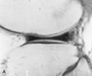
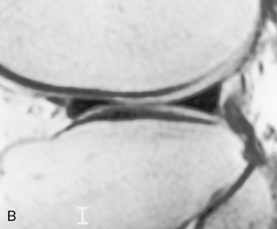
 Normal meniscus. A, A T1-weighted sagittal image through a normal lateral meniscus demonstrates uniform low signal in the meniscus. This is a section through the body of the meniscus, because it has a bowtie configuration. Two sections of the body should be seen in each meniscus with 4- or 5-mm thick slices. B, In the same T1-weighted sequence, this sagittal image demonstrates uniform low signal in the anterior and posterior horns of this normal lateral meniscus. (Anterior is to the left.)
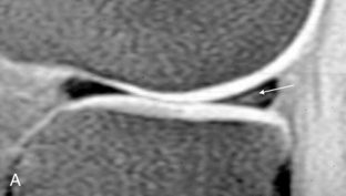
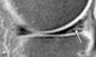
 Intrasubstance degeneration. A, Faint intermediate signal can be seen in the posterior horn of this meniscus (arrow), which does not disrupt the articular surface of the meniscus. This is intrasubstance degeneration. B, Linear high signal is present in the posterior horn of the meniscus (arrow). The signal does not disrupt the articular surface; therefore this represents intrasubstance degeneration.

 Grading scale for menisci. A schematic of the MRI grading scale for meniscal abnormalities: Grade 1 has rounded or amorphous signal in the meniscus that does not disrupt an articular surface. Grade 2 has linear signal that does not disrupt an articular surface. Grades 1 and 2 represent intrasubstance degeneration. Grade 3 has signal that does disrupt an articular surface and indicates a meniscal tear.
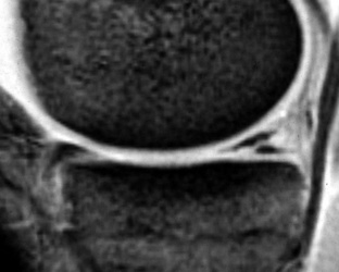
 Meniscal tear. This fat-suppressed T1-weighted sagittal image shows linear high signal in the posterior horn of the meniscus, which disrupts the inferior articular surface. This is the appearance of an oblique meniscal tear.
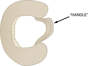
 Bucket handle tear. This drawing illustrates a bucket handle tear with the torn free edge of the meniscus displaced as the “handle” of the bucket.
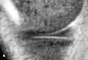
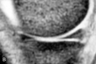
 Bucket handle tear. Sagittal gradient-echo images through the medial meniscus at its most medial aspect reveal one bowtie, indicative of the body of the meniscus (A), with the adjacent image (B) having apparent normal anterior and posterior horns. However, because there should be two consecutive sagittal images with a bowtie configuration, this indicates a bucket handle tear. (Anterior is to the left.)
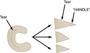
 Schematic of bucket handle tear. This drawing shows how a vertical longitudinal tear as shown on the axial view (left) can appear on the coronal views (right). Before the free edge is displaced, the tear may be seen (top, right); after the free edge (or “handle”) displaces, the remaining meniscus may appear truncated (center, right); after weight bearing the truncated meniscus smooths out to a sharp triangle that is simply decreased in width from the normal (bottom, right).
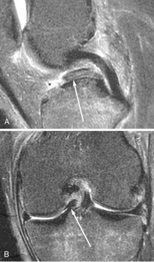
 Displaced fragment in bucket handle tear. (A) Sagittal and (B) coronal T2-weighted images through the intercondylar notch in a patient with a bucket handle tear reveals the displaced free fragment or “handle” (arrows) just anterior to the posterior cruciate ligament.
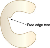
 Parrot beak tear. This drawing shows the appearance of a radial free edge meniscal tear called a parrot beak tear.
Magnetic resonance imaging of the knee


