, C. Delorenzo1 , X. Papademetris2 and J. S. Duncan1
(1)
Center for Understanding Biology using Imaging Technology (CUBIT), Stony Brook University, Stony Brook, NY 11794, USA
(2)
Department of Diagnostic Radiology and Biomedical Engineering, Yale University, 300 cedar St, TAC N119, New Haven, CT 06519, USA
Abstract
Estimating tissue displacement and deformation from time-varying medical images is a common problem in biomedical image analysis. For example, in order to better manage patients with ischemic heart disease, it would be useful to know their current extent of injury. This can be assessed by accurately tracking the motion of the left ventricle of the beating heart. Another example of this type of application is estimating the displacement of brain tissue during neurosurgery. The latter application is necessary because the presurgical planning for these delicate surgeries is based on images that may not accurately reflect the intraopertave brain (due to the action of gravity and other forces). In both examples, the tissue deformation cannot be measured directly. Instead, a sparse set of (potentially noisy) displacement estimates are extracted from acquired images. In this chapter, we explain how to use the physical properties of underlying organs or structures to guide such estimations of deformation, using neurosurgery and cardiac motion as example cases.
1 Introduction
Estimating displacements and deformations of real world objects from time-varying medical images is a common problem in biomedical image analysis. In such problems, the physical properties of the underlying organs or structures can be used to guide this information recovery process. For example, knowledge of the fiber architecture of the heart can be used as a constraint in the estimation of cardiac deformation [41]. This type of real displacement estimation stands in contrast to the more common domain of non-rigid image registration methods where the goal is to estimate displacement fields that map, for example, brains from two difference subjects to the same coordinate system. Confusingly, in the case of image registration, physical models are also often used to regularize the displacement estimation process (e.g. see [12, 21]) as they often possess desirable mathematical properties. However, in the cases of the problems described in this chapter, we employ physical models precisely to take take advantage of research in the biomechanics community (e.g. [25]) about the material properties of the underlying tisses as an aid the displacement estimation process.
Two of the most common areas of biomedical image analysis in which physical models have been employed are (i) the estimation of brain shift (and generally deformation) during neurosurgery and (ii) the estimation of left ventricular deformation over time. While these are, on the surface, very different problems we note that there exist a number of common threads between them. Fundamentally, in both cases, the goal is to estimate a dense and smooth displacement field over the whole space covered by the structure of interest (e.g. the brain or the left ventricle of the heart). However, usually what is available directly from the images are sparse, noise-corrupted and often partial (i.e. only some of the components are measurable) measurements of the actual displacement, often clustered on the outer surface of the organ.
The goal of much of this work is to use these measured displacements as an input and to leverage physical and geometrical models to essentially approximate/interpolate between these measurements to generate a smooth, dense and complete displacement field. To accomplish this we use patient specific geometric models derived from the image data to build either a finite element or a boundary element model of the underlying organ together with generic biomechanical models with parameters set based on the biomechanics literature. We emphasize that these models do not aim to predict the deformation in the style of forward models, but rather should be thought off as smart and optimal interpolation/approximation techniques.
We use two examples studies to illustrate the use of this underlying mathematical framework. In Sect. 2 we describe methodology to compensate for brain shift in image guided neurosurgery using finite element methodology and in Sect. 3 we describe algorithms to estimate the deformation of the left ventricle of the heart using a boundary element based approach.
2 A Finite Element Based Approach: Brain Shift Compensation for Image Guided Neurosurgery
2.1 Background
Prior to brain surgery, neurosurgeons may acquire images of different modalities to delineate pathologic regions. One of the major challenges during neurosurgery is the localization of these pathologic targets within the brain anatomy. Surgical navigation systems can aid intraoperative navigation by rigidly registering the patient to preoperative images and then displaying the current position of surgical instruments relative to these images. In these cases, the patient data is usually registered only once [10, 24, 43], assuming that the brain and other intracranial structures are rigid and will stay fixed relative to the skull. However, during surgery, the brain can deform up to five centimeters or more due to gravity, loss of blood and cerebrospinal fluid, swelling, surgical manipulation and the action of certain medications [4, 14, 20, 22, 23, 27, 45]. This nonrigid brain shift is the primary cause of intraoperative localization inaccuracies [16].
Due to the large number of contributing factors, it is nearly impossible to predict the exact pattern of brain deformation preoperatively [19, 44]. Therefore, intraoperative information is often necessary to compute the magnitude of brain shift. This information can be either surface or volume based. Though volumetric images, acquired by intraoperative magnetic resonance imaging (iMRI), computed tomography (iCT) or ultrasound (iUS), provide visualization of deformation throughout the entire brain, these methods are either invasive or costly [27, 39]. Additionally, the necessary image acquisition time can substantially lengthen surgery [44]. Using surface based information, acquired by laser range scanners (LRS) [3, 9, 18, 39, 46] or stereo cameras [47, 51], avoids these problems. However, while sometimes capable of achieving high accuracy, both LRS and stereo can be affected by resolution issues, which can compromise surface deformation estimations.
Since the LRS and stereo methods only acquire intraoperative information at the cortical surface, these methods are typically used in conjunction with a biomechanical model to infer volumetric deformation. Biomechanical models are also often used with volumetric imaging data because preoperative to intraoperative volumetric image matching can be difficult.
2.2 The Finite Element Method (FEM)
The finite element method is a numerical analysis technique for obtaining approximate solutions to a wide variety of engineering problems [29]. The key to this method is that the domain of problem is divided into small areas or volumes called elements. The problem is then discretized on an element by element basis and the resulting equations assembled to form the global solution.
An Example Problem:
In this section, we describe an example problem and outline a possible solution using FEM in an energy minimization framework. The goal is to estimate a displacement field, u(x, y, z), that is the optimal trade off between an internal energy function, W(u),1 and an approximating noisy displacement field, u m (x, y, z).
We define the optimal solution displacement field, u, as the one that minimizes functional P(u) in a weighted least squares sense:


W(u) can be defined using a strain energy function as W = e t Ce, where e is local tissue strain and C, the material stiffness matrix, is a function of the displacement field (u), spatial position (m), and the tissue’s material properties-Young’s modulus (E) and Poisson’s Ratio (ν). V (u, u m ) is the external energy term, based on u m , an original displacement estimate, and α, the confidence in the match. We will focus here primarily on the first term, W(u).
Outline of the Solution Procedure:
Step 1: Divide Volume into elements (tetrahedra or hexahedra) to provide the basis functions for the discretization.
Step 2: Discretize the problem by approximating the displacement field in each element as a linear combination of displacements at the nodes of each element. For a hexahedral element, this discretization can be expressed as:  where Ni is the interpolation shape function for node i and ui is the displacement at node i of the element.
 where Ni is the interpolation shape function for node i and ui is the displacement at node i of the element.
Step 3: Write the internal energy equation as the sum of the internal energy for each element, v el :
![$$ W(u)={\sum_{\mathit{all} \; \mathit{elements}}\left[{{\int}_{\upsilon_{e l}}{e}^t \mathit{Ced}}\left({\upsilon}_{e l}\right)\right]} $$](/wp-content/uploads/2016/09/A151032_1_En_17_Chapter_Equ1.gif)
![$$ W(u)={\sum_{\mathit{all} \; \mathit{elements}}\left[{{\int}_{\upsilon_{e l}}{e}^t \mathit{Ced}}\left({\upsilon}_{e l}\right)\right]} $$](/wp-content/uploads/2016/09/A151032_1_En_17_Chapter_Equ1.gif)
(1)
We can approximate the derivatives of u in an element with respect to components of the global coordinate system, x, as follows (note that the u i are constant in this expression):


The derivatives of the displacement field, u, (i.e.  ) are linear functions of the nodal displacements, u i . Since the infinitesimal strain tensor consists of only sums and differences of partial derivatives, this tensor can also be expressed as a linear function of the nodal displacements by e = Bu. (See Bathe [7] for nonlinear extensions of the finite strain deformation case.) Substituting this into equation (1) yields:
![$$ W(u)={\displaystyle \sum_{\mathit{all} \; \mathit{elements}}{U}^{e t}\left[{\displaystyle {\int}_{\upsilon_{e l}}{B}^t CBd}\left({\upsilon}_{e l}\right)\right]}\ {U}^e={\displaystyle \sum_{\mathit{all} \; \mathit{elements}}{U}^{e t}\left[{K}^e\right]}\ {U}^e $$](/wp-content/uploads/2016/09/A151032_1_En_17_Chapter_Equc.gif) where K e is the element stiffness matrix, and U e is a vector obtained by concatenating all the displacements of nodes in the element, i.e., U e = [u 1,x , u 1,y , u 1,z , . . . , u 8,x , u 8,y , u 8,z ] where u i = (u i,x , u i,y , u i,z ) is the displacement of node i.
where K e is the element stiffness matrix, and U e is a vector obtained by concatenating all the displacements of nodes in the element, i.e., U e = [u 1,x , u 1,y , u 1,z , . . . , u 8,x , u 8,y , u 8,z ] where u i = (u i,x , u i,y , u i,z ) is the displacement of node i.
 ) are linear functions of the nodal displacements, u i . Since the infinitesimal strain tensor consists of only sums and differences of partial derivatives, this tensor can also be expressed as a linear function of the nodal displacements by e = Bu. (See Bathe [7] for nonlinear extensions of the finite strain deformation case.) Substituting this into equation (1) yields:
![$$ W(u)={\displaystyle \sum_{\mathit{all} \; \mathit{elements}}{U}^{e t}\left[{\displaystyle {\int}_{\upsilon_{e l}}{B}^t CBd}\left({\upsilon}_{e l}\right)\right]}\ {U}^e={\displaystyle \sum_{\mathit{all} \; \mathit{elements}}{U}^{e t}\left[{K}^e\right]}\ {U}^e $$](/wp-content/uploads/2016/09/A151032_1_En_17_Chapter_Equc.gif)
Step 4: Rewrite the internal energy function in matrix form. First, define the global displacement vector, U, as U = [u 1,x , u 1,y , u 1,z , . . . , u n,x , u n,y , u n,z ] t , where n is the total number of nodes in the solid. Then, define the global stiffness matrix, K, as the assembly of all the local element stiffness matrices, K e :

where  is the re-indexing function, which takes element
  and adds it to the element K kl , where k and l are the global node numbers of local nodes i and j.2

(2)
 is the re-indexing function, which takes element
  and adds it to the element K kl , where k and l are the global node numbers of local nodes i and j.2
 The internal energy can now be written as W(U ) = U t KU.
Applying External Data Constraints: The rest of the process involves the formulation of the external energy term, which is problem specific. Let’s assume for now that this term can be posed in quadratic form as V(U ) = (U m − U) t A(U m − U ). Once this is in place, the sum of W(U) + V(U) can be minimized, by differentiation with respect to U, and set to zero. This results in the final equation:

Equation (3) can be solved for U using sparse matrix methods.3 Since U represents the values of u at each node, we can compute the resulting values of the displacement field u anywhere in the volume by means of the finite element approximation  .
.

(3)
 .
.2.3 System Description
Our approach to brain shift compensation, outlined on the left side of Fig. 1, employs a 3D biomechanical brain model guided by sparse intraoperative data. The intraoperative data is acquired by stereo camera images and consists of cortical surface intensities and features (sulci). We use a game theoretic framework to overcome the resolution issues associated with stereo imaging and predict the cortical deformation. The application of this method requires discretizing the preoperative brain into small elements (right side of Fig. 1) and applying the finite element method (Sect. 2.2) to determine each element’s displacement.
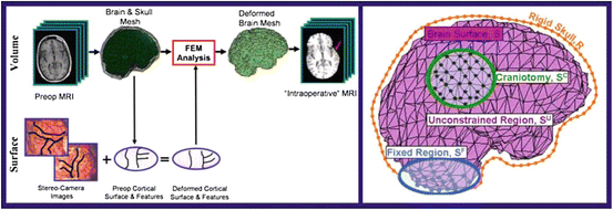

Fig. 1
Left: The brain and skull are extracted from the preoperative MRI, serving as inputs, along with the deformed cortical surface, to the FEM volume calculation. The FEM result is the deformed position of every brain mesh node. This mesh is then resampled into the original image space to yield a simulated “intraoperative” MRI. The red arrow indicates the region of greatest deformation. Right: Sample brain mesh with surface node labels. (See Sect. 2.3)
Image-based Displacement Estimates:
In order to obtain accurate quantitative information from stereo cameras, as with any imaging system, calibration is usually necessary. However, in many real world situations, accurate calibrations are not possible [34]. This is especially true in the operating room, where extreme time and space constraints limit the calibration procedure possibilities. (See [52] for calibration methods and the use of calibration parameters to project 3D points onto images.) The resulting inaccurate camera calibrations decrease image resolution and compound the difficulty of image-derived deformation estimation.
Therefore, in order to track the deforming cortical surface, a framework with the ability to solve for competing variables (surface displacement field/accurate camera calibration parameters) is needed. Game theory, the study of multiperson decision making in a competitive environment [6, 36], can provide this framework. In a game theoretic formulation, the players are computational modules. In the context of intraoperative neurosurgical guidance, the players would be 1)  , the dense displacement field applied to the preoperative cortical surface and 2)
 ![$$ {\underline{\mathbf{A}}}=[\underline{{A_0}},\underline{{A_1}}] $$](/wp-content/uploads/2016/09/A151032_1_En_17_Chapter_IEq9.gif) , the camera calibration parameters for the left (0) and right (1) stereo cameras. This analysis therefore updates surface displacement and calibration parameter estimates at every iteration.
, the camera calibration parameters for the left (0) and right (1) stereo cameras. This analysis therefore updates surface displacement and calibration parameter estimates at every iteration.
 , the dense displacement field applied to the preoperative cortical surface and 2)
 ![$$ {\underline{\mathbf{A}}}=[\underline{{A_0}},\underline{{A_1}}] $$](/wp-content/uploads/2016/09/A151032_1_En_17_Chapter_IEq9.gif) , the camera calibration parameters for the left (0) and right (1) stereo cameras. This analysis therefore updates surface displacement and calibration parameter estimates at every iteration.
, the camera calibration parameters for the left (0) and right (1) stereo cameras. This analysis therefore updates surface displacement and calibration parameter estimates at every iteration.The model for determining these variables, expressed in a game theoretic formulation is:


(4)

(5)
where C1, C2 are the cost functions for the dense displacement field and camera calibration parameters, respectively. These cost functions can be iteratively minimized until they reach equilibrium, representing the algorithm solution [11]. The constants in these functions, α and β, are chosen using game theoretic constructs for noncooperative games, in which collusion between players is prevented and the players can pursue their own interests, which may conflict [6, 11]. The other terms are presented below.
Displacement Field Determination: The intensity correlation term matches the stereo image intensities that are backprojected onto the exposed brain surface. A backprojected image (Fig. 2DD) is defined as  , where S is the deformed surface, I is an intraoperative stereo image, P is a standard camera projection function from the surface to the images and i represents the camera number (0 or 1). This term can be written as
  where NCC is the normalized cross correlation and η is a normalizing constant, ensuring that all terms have similar orders of magnitude.

 , where S is the deformed surface, I is an intraoperative stereo image, P is a standard camera projection function from the surface to the images and i represents the camera number (0 or 1). This term can be written as
  where NCC is the normalized cross correlation and η is a normalizing constant, ensuring that all terms have similar orders of magnitude.
Fig. 2
Mean (A) and maximum (B) displacement and algorithm error (α = 4, β = 0.83, ρ = 0.1, η = 25). In (C), intraoperative images of Data Set #2 show the misalignment of projected preoperative sulci (green) with intraoperative sulci positions (black) due to brain shift and camera calibration errors. Predicted sulci positions, projected with the updated calibration parameters (yellow), show better alignment. Backprojected intensities (D) are found by projecting each point on the surface to the left (left column) or right (right column) image and assigning the associated image intensity value to that point. Red arrows indicate the misalignment between the sulci on the preoperative surface (green) and those seen in the backprojected image. Sulci on the algorithm-predicted surface (yellow) are better aligned with the image intensities
A feature matching term measures the distance between 3D sulci on the cortical surface,  which are projected into the stereo images, and the intraoperative sulci outlined in those images,
 ![$$ \underline{\mathbf{K}}=[\underline{K_0},\underline{{K_1}}] $$](/wp-content/uploads/2016/09/A151032_1_En_17_Chapter_IEq13.gif) . The imaged sulci are manually extracted by an expert user and stored as 2D curves. This term can be expressed by:
. The imaged sulci are manually extracted by an expert user and stored as 2D curves. This term can be expressed by:
![$$ \begin{aligned} {T}_F\left(\underline{{\mathbf{U}}_{\mathit{dns}}},\underline{\mathbf{A}}\right)&=-\left( \int d\left[\underline{{K_0}}, P\left({A}_0,\left(\underline{\mathbf{C}}+\underline{{\mathbf{U}}_{\mathit{dns}}^C}\right)\right)\right]\right.dS \\ &\qquad\left.+{\int d\left[\underline{{K_1}}, P\left({A}_1,\left(\underline{\mathbf{C}}+\underline{{\mathbf{U}}_{\mathit{dns}}^C}\right)\right)\right] dS}\right),\end{aligned} $$](/wp-content/uploads/2016/09/A151032_1_En_17_Chapter_Equd.gif) where
where  is the dense displacement field restricted to the sulci and d is a mean Euclidean distance metric.
 which are projected into the stereo images, and the intraoperative sulci outlined in those images,
 ![$$ \underline{\mathbf{K}}=[\underline{K_0},\underline{{K_1}}] $$](/wp-content/uploads/2016/09/A151032_1_En_17_Chapter_IEq13.gif) . The imaged sulci are manually extracted by an expert user and stored as 2D curves. This term can be expressed by:
. The imaged sulci are manually extracted by an expert user and stored as 2D curves. This term can be expressed by:![$$ \begin{aligned} {T}_F\left(\underline{{\mathbf{U}}_{\mathit{dns}}},\underline{\mathbf{A}}\right)&=-\left( \int d\left[\underline{{K_0}}, P\left({A}_0,\left(\underline{\mathbf{C}}+\underline{{\mathbf{U}}_{\mathit{dns}}^C}\right)\right)\right]\right.dS \\ &\qquad\left.+{\int d\left[\underline{{K_1}}, P\left({A}_1,\left(\underline{\mathbf{C}}+\underline{{\mathbf{U}}_{\mathit{dns}}^C}\right)\right)\right] dS}\right),\end{aligned} $$](/wp-content/uploads/2016/09/A151032_1_En_17_Chapter_Equd.gif)
 is the dense displacement field restricted to the sulci and d is a mean Euclidean distance metric.
A prior term,  , where ρ is a normalizing constant and
  is the second derivative of the dense displacement field, ensures deformation smoothness.
 , where ρ is a normalizing constant and
  is the second derivative of the dense displacement field, ensures deformation smoothness.
Stay updated, free articles. Join our Telegram channel

Full access? Get Clinical Tree


