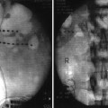
Fig. 41.1
MRI showing the central sulcus and the precentral gyrus
Surgical Procedure and Intraoperative Electrophysiological Mapping
The placement of the MCS electrodes may be performed through a burr hole or a small craniotomy. Our preference is to perform it through a small craniotomy centered over the region identified as the precentral gyrus during preoperative planning. This larger access allows for placement of epidural electrodes and optimizes intraoperative electrophysiological evaluation.
The procedure is performed under general endotracheal anesthesia while avoiding paralytic agents as these can interfere with electrical cortical mapping using electromyographic (EMG) responses. Some centers elect to perform awake procedures with monitored anesthesia care (MAC). The head is fixed with a three-pin head holder. The outline of the precentral gyrus is projected onto the scalp using preoperative imaging fused with a frameless neuronavigation system. An appropriate incision centered over this region is made, and then, a 4-cm craniotomy, which is large enough to allow for epidural placement of a 4 × 4 electrode grid, is fashioned. The 16-electrode grid is then placed in the epidural space (Fig. 41.2).
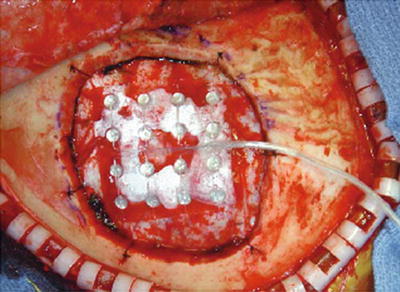
Fig. 41.2
16-Electrode grid placed in the epidural space
There are two main objectives of intraoperative electrophysiological testing – (1) the confirmation of the position of central sulcus (following earlier localization using preoperative imaging) and (2) the confirmation of the position of the motor cortex by stimulation.
The position of the central sulcus may be confirmed using somatosensory evoked potentials (SSEPs). The site and orientation of the central sulcus is identified based on N20-P20 wave shift (phase reversal) obtained during SSEP recordings (Fig. 41.3). Following this determination, the position of the motor cortex is then confirmed by stimulation via the electrode grid. In performing this test, stimulation of increasing intensity is applied while watching for motor contractions at the lowest stimulation threshold in the zone corresponding to the region of pain in the non-paralyzed patient. It is important to note that motor seizures can be provoked by the cortical stimulation. Cold saline or lactated ringer’s solution should be immediately available for irrigation of the motor cortex in case of a seizure. The position of the stimulating electrodes which produced motor contractions at the lowest threshold in the appropriate region of the body is noted and marked on the dura. This position defines the optimal site for motor cortex stimulation.
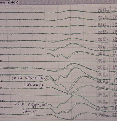
Fig. 41.3
The site and orientation of the central sulcus is identified based on N20-P20 wave shift (phase reversal) obtained during SSEP recordings
Implantation of MCS Electrodes
Two two-plate paddle electrode arrays are then placed in the epidural space in the previously determined optimal position and are oriented perpendicularly to the central sulcus and sutured to the dura (Fig. 41.4). Alternatively, a four-plate Resume electrode array may be used, and in this case, the electrodes may be placed perpendicularly or parallel to the central sulcus. Some investigators have placed these electrodes in the subdural space [21]. Following placement, the electrodes are connected to extension leads, which are tunneled externally and connected to an external pulse generator for testing of the efficacy of stimulation over several days.
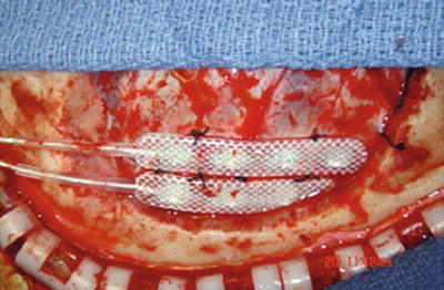
Fig. 41.4
Two two-plate Medtronic Resume paddle electrode arrays placed in the epidural space and oriented perpendicularly to the central sulcus and sutured to the dura
Externalized MCS Trial, Stimulation Parameters, and Internalization of Stimulation System
The externalized MCS trial stimulation is generally performed over 3–5 days. Patient should be monitored during the trial in an epilepsy monitoring unit, an intensive care unit, or the neurosurgical floor. During the trial, the stimulation amplitude is set at a value of 80 % of the threshold for motor contraction. Typical stimulation parameters used are amplitudes of 1–3 V, frequency of 40 Hz, and pulse width of 90 ms. A trial is considered successful if patients report at least 50 % pain relief with stimulation.
Patients who have a successful trial are then returned to the operating room for internalization of the stimulator system. The scalp flap is only partially reopened during this second procedure to expose the MCS electrode lead that was coiled under the galea of the scalp at the first procedure. This lead is then connected to an extension wire which is tunneled under the skin and connected to an implantable pulse generator (IPG), which is typically placed in a subcutaneous or subfascial pocket created in the infraclavicular region (Fig. 41.5).
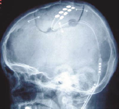
Fig. 41.5
The lead is connected to an extension wire which is tunneled under the skin and connected to an implantable pulse generator (IPG), which is typically placed in a subcutaneous or subfascial pocket created in the infraclavicular region
Related posts:
 Transforaminal Epidural Steroid Injections
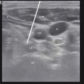 Stellate Ganglion Blockade
 Clinical Applications of Neuromodulation: Section on Angina and Peripheral Vascular Disease
 Superior Hypogastric Plexus, Ganglion Impar Blocks, and Neurolysis
 Spinal Targets for Interventional Pain Management
 Stimulation of the Peripheral Nerve and Peripheral Nerve Field
Stay updated, free articles. Join our Telegram channel

Full access? Get Clinical Tree


