Fig. 5.1
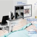
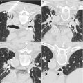
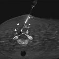
The interventional MRI unit at The University of Texas MD Anderson Cancer Center is equipped with a short (125 cm) expanded diameter (70 cm) bore in a 1.5-T MRI scanner (Magnetom Espree, Siemens Medical Solutions, Erlangen, Germany). In-room monitors are available for the radiologist to use while performing an intervention
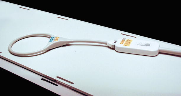
Fig. 5.2
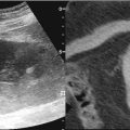
A standard Siemens large-loop coil has a diameter of 17 cm. This coil provides good image quality for superficial lesions
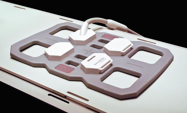
Fig. 5.3
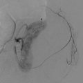
A standard Siemens body array coil has six elements and provides better image quality for deeper targets than does the large-loop coil. On the other hand, the body coil has small openings (10 cm) that limit access to the patient and the biopsy site
Positioning of the coils, equipment, and patient within the bore must be performed by experienced MRI personnel so as to minimize risk of excessive heating from the radiofrequency excitation pulses used during imaging. Additionally, because of the radiofrequency pulses and high magnetic field in the room, safety regulations require screening of patients and staff. During real-time imaging, the rapidly switched gradients result in high noise levels in the room so that hearing protection must be worn by patient and staff alike. Dedicated MRI-compatible communication systems are very useful for communicating with staff during real-time imaging (Fig. 5.4). Additionally, all ancillary equipment that will be used on the patient in the suite needs to be safe for the MRI environment. MRI-compatible patient-monitoring devices are required to perform interventional procedures in the MRI suite. Fortunately, these devices are widely available in most MRI suites as some patients may require sedation during imaging and therefore require hemodynamic monitoring [9]. Similarly, MRI-compatible anesthesia equipment is commercially available.
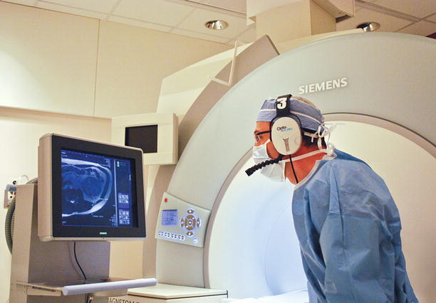

Fig. 5.4
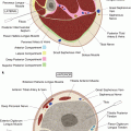
During a typical MRI-guided intervention, the radiologist stays in the MRI suite during imaging. Ear protection and communication is accomplished using an MRI-compatible fiber-optic communication system (IMROC, OptoAcoustics Ltd., Or-Yehuda, Israel). An in-room monitor provides updated images in real time for the radiologist to view
Finally, several ancillary devices can be extremely helpful in facilitating MRI-guided interventions. First, a tableside monitor located in the MRI suite may be used by the operator to review images immediately prior to or subsequent to any needle manipulation (Figs. 5.1 and 5.4). Such equipment has become an option with most major MRI manufacturers and is an essential component for executing real-time MRI-guided biopsies. Additionally, tableside control buttons to perform simple tasks, such as starting and stopping a prescribed imaging sequence or quickly moving the patient in and out of the bore of the magnet during intermittent imaging, can markedly improve the workflow for the interventional radiologist (Fig. 5.5).
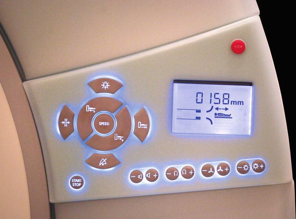

Fig. 5.5
Tableside controls allow the radiologist to perform simple tasks without the assistance of the technologist. Two of the most important functions are moving the patient in and out of the unit and starting and stopping an imaging sequence
At the University of Texas MD Anderson Cancer Center, our initial experience with MRI-guided biopsies began with the use of a 1.5 T conventional cylindrical MRI unit (Signa Excite, GE Healthcare, Waukesha, WI). This system is an older magnet design with a bore length of 175 cm and a high-performance gradient package (Cardiac Resonance Module: maximum amplitude of 40 mT/m and slew rate of 150 T/m/s) resulting in a smaller than average bore diameter of 55 cm. These dimensions precluded any real-time access to the patient within the bore of the magnet. Imaging was performed with the patient at the isocenter of the magnet, and needle manipulation was performed with the patient moved back to landmark outside the bore of the magnet after reviewing the acquired images.
Conventional receive-only radiofrequency coils (13-cm diameter surface coil or 4-channel torso array) were used for biopsy. The 4-channel torso array coil had a reasonably large (17.0 × 10.5 cm) aperture for adequate patient access and good signal-to-noise ratio at depth compared with the surface coil. The torso array consisted of anterior and posterior components that worked together to provide good signal-to-noise ratio across the target region. To mark the needle insertion site on the patient, we used the existing patient localizer light in front of the magnet. Patients were first positioned in a manner most conducive to performing the intervention based on prior imaging studies, then the region of interest was imaged using a fast, balanced steady-state free-precession sequence for T2-like contrast. Planning was usually performed using the axial plane. Once the most appropriate plane of approach was identified, the patient couch was brought out of the scanner and that plane brought to the landmark location illuminated by the light. Fiducials placed on the patient were used to localize the entry point in the lateral direction. Planning from a sagittal plane was similar but required using the lateral localizer light as a point of reference. Because of the dependence on the localizer lights, the accuracy of these lights was incorporated into the scanners daily quality assurance routine.
Patients were monitored using standard hemodynamic monitoring equipment (Magnitude 3150 MRI, Invivo Corporation, Orlando, FL). One major drawback of working on this particular MRI system was the lack of a tableside monitor for the operator to review the most recent images prior to manipulation of the needle. Another limitation was the lack of a communication system between the operator in the MRI suite and the personnel in the control room. These limitations, in concert with limited access to the patient, severely limited procedural workflow, the types of procedures that could be performed, and patient selection. This made it difficult and time consuming for the interventional radiologist to effectively triage patients for procedures in this room.
Experience using an existing 1.5 T clinical MRI for interventional procedures guided our prospective specification of a new system that was to be dedicated for interventions. Our current iMRI suite is equipped with a short (125 cm), expanded diameter (70 cm) bore in a 1.5 T MRI scanner (Magnetom Espree, Siemens Medical Solutions, Erlangen, Germany). This system features gradients with maximum amplitude of 33 mT/m and slew rates of 170 T/m/s and the Siemens 18-channel total imaging matrix technology running the B17 software platform (Fig. 5.1). Two in-room MRI consoles facilitate in-room visualization and access to MRI controls during procedures (Fig. 5.4). Additional control buttons are located at three locations around the magnet, allowing the operator to start and stop imaging or to move the patient in and out of the magnet as needed (Fig. 5.5). The MRI suite also features an integrated, floor-mounted fluoroscopy unit (Axiom Artis, Siemens Medical Solutions) located outside the 5-gauss line and a specially designed patient transfer table that moves the patient smoothly between MRI and angiography (MR-Miyabi, Siemens).
At our center, standard Siemens radiofrequency coils are used during biopsy procedures. For most procedures, the patient is placed atop the spine coil, the signal of which is combined with the surface coil placed on the opposite side of the patient. The primary coils used on the surface of the patient where needle entry is planned include a six-element phased-array body coil and a large-loop surface coil (Figs. 5.2 and 5.3). The body coil has four small openings that can be positioned immediately over the biopsy site. The openings of the body coil are small (10 × 10 cm), which somewhat impedes access to the biopsy site. The access granted by the large-loop coil (17-cm diameter) is more amenable to biopsy procedures; however, image quality at depth is inferior compared with the body array coil. These coils are not sterilized for each procedure; instead, they are placed between two sterile “keyhole” drapes.
Real-time image-guided interventions require the operator to remain in the iMRI suite. Ear protection and communication is accomplished using an MRI-compatible fiber-optic communication system (IMROC, OptoAcoustics LTD, Or Yehuda, Israel) (Fig. 5.4). The system has six channels—one channel for the patient and five channels for the staff in the iMRI suite. The microphones have noise cancellation capabilities to minimize the noise from the scanner and to accentuate voices. The headphones provide 30-dB passive noise reduction. The lines of communication can be controlled between the operators, the patient, and the control room using a mixing box that is positioned in the MRI control room. From the control room, the MRI operator can listen or speak to anyone on the system. One limitation of the system is the fiber-optic cables that tether each individual to the system and complicate movement around the suite; however, a wireless system has become available recently.
Needles are visualized on MRI because of their magnetic susceptibility artifact, which depends on the raw material of which the needle is made, the size and shape of the needle, and the field strength of the magnet (Fig. 5.6) [7, 10–12]. Relatively inexpensive alloys such as high-nickel, high-chromium, and stainless steel may create an acceptable susceptibility artifact for a 0.2 T magnet, but the artifact may be quite large for 1.5 T magnets. With the current trend toward higher magnetic fields, most MRI-compatible needles are made of titanium or nitinol. In the United States, there are only a few companies that market MRI-compatible needles, and most MRI-compatible needles are geared toward breast biopsy procedures, limiting their length and caliber. The Invivo Corporation provides the largest selection of needles for aspiration and core tissue biopsies. Some bone biopsy needles are also available through the Invivo Corporation. MRI-compatible fine-needle aspiration biopsy needles are also available through Cook Medical (Bloomington, IN).
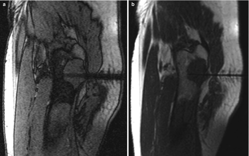
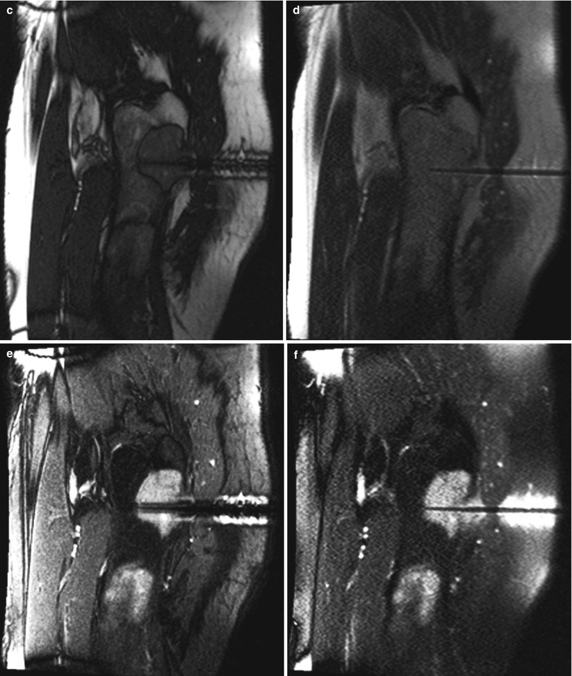


Fig. 5.6
A 61-year-old man with a history of unclassified sarcoma presented with a lytic lesion involving the proximal left femur. A biopsy was performed under MRI guidance, using a 12-gauge guide needle so that 14-gauge core biopsy samples could be obtained. An out-of-phase, T1-weighted GRE image (a) in the sagittal plane reveals a larger needle artifact and a lower signal-to-noise ratio than do the T1-weighted TSE (b) and bSSFP (c) images. In this case, the T2-weighted contrast of bSSFP provided better contrast and a higher signal-to-noise ratio than did the T2-weighted HASTE image (d). On the other hand, the tip of the biopsy needle is more sharply identified on the HASTE image (d). Suppression of the bright fat signal in the bSSFP (e) and HASTE (f) images further increases the conspicuity of the needle and the lesion against the background
Advantages
There are several advantages in using MRI to guide percutaneous biopsies. First, MRI provides excellent soft-tissue contrast and exquisite anatomic detail. MRI helps localize tumors that may not be easily detected with CT or ultrasound, and MRI visualizes the anatomy surrounding the biopsy target (Figs. 5.7, 5.8, and 5.9) [6, 13, 14]. This is particularly important in detecting and targeting bone and soft-tissue tumors for which CT and ultrasound may be inadequate [15]. The use of different pulse sequences during MRI-guided interventions allows the operator to elicit different tissue characteristics within the biopsy target and the surrounding structures (Figs. 5.7 and 5.9). The use of T1- and T2-weighted pulse sequences and the application of fat suppression-, perfusion-, and diffusion-weighted images can help direct the intervention to the most relevant location within the tumor (Fig. 5.10). Easy detection and continuous visualization of vascular structures during the procedure without the need for intravenous contrast medium helps reduce the risk of hemorrhagic complications. The multiplanar imaging capability of MRI is highly desirable to guide biopsies of tumors that are in difficult locations (Figs. 5.11 and 5.12). For example, tumors in the dome of the liver can be targeted using any of the sagittal, coronal, or double-oblique imaging planes. Imaging in any conceivable plane allows on-the-fly adjustments such that the entire biopsy needle and the target tissue are simultaneously visualized on one image. When compared to CT, MRI has no ionizing radiation, which is particularly important in pediatric patients, in women of childbearing age, and to physicians and their staff who may be exposed to radiation during CT or fluoroscopic procedures. Long imaging acquisition times were once a major limitation of MRI-guided interventions such as biopsies. Ultrafast imaging sequences with high signal-to-noise ratio and soft-tissue contrast are now available, allowing fast imaging of the biopsy needle position after each manipulation.
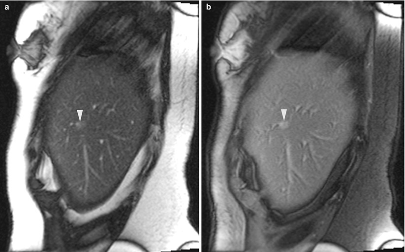
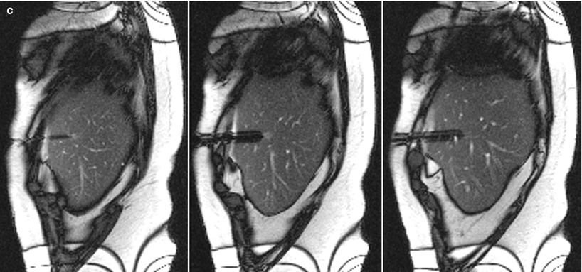


Fig. 5.7


A 60-year-old woman with a history of breast cancer and pancreatic neuroendocrine tumor was found to have a sub-centimeter liver lesion. A sagittal trueFISP image (a) of the liver reveals a small ill-defined lesion (arrowhead). After suppression of the fat signal (b), the tumor is better visualized (arrowhead). Real-time MRI guidance was used in the sagittal plane, with no breath-hold instructions. A montage of three sequential sagittal images (c) reveals the tip of the guide needle at the edge of the tumor in the center image. A pathologic evaluation revealed a metastatic neuroendocrine tumor
Stay updated, free articles. Join our Telegram channel

Full access? Get Clinical Tree


