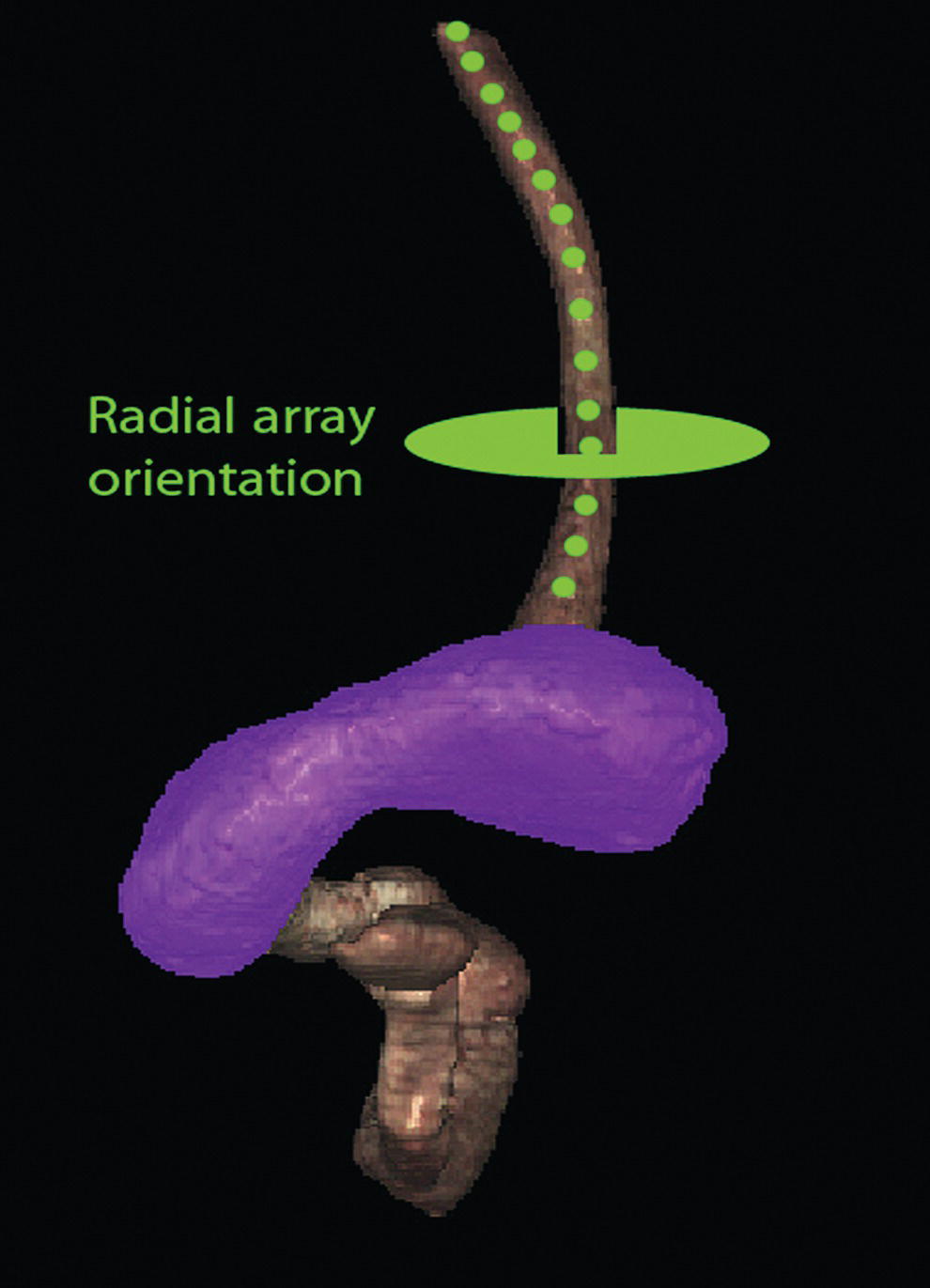
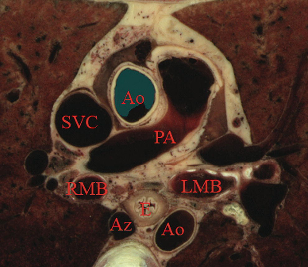
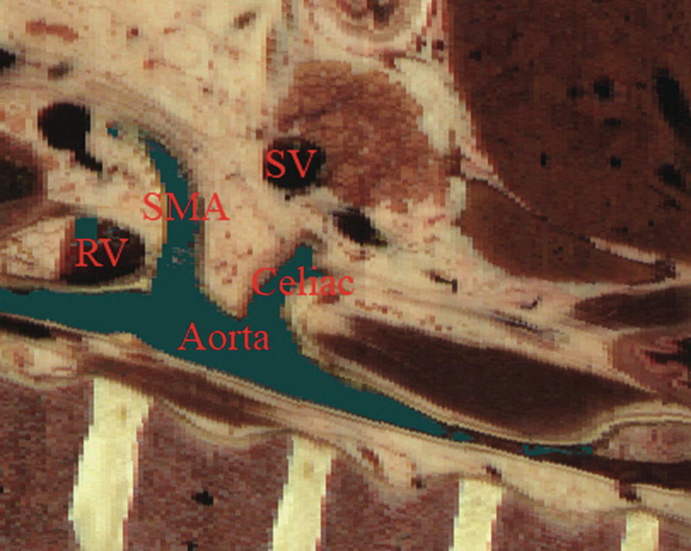
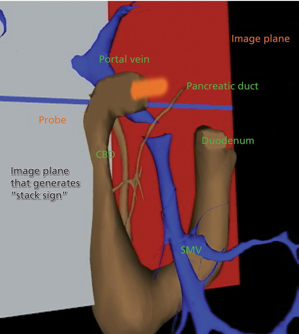
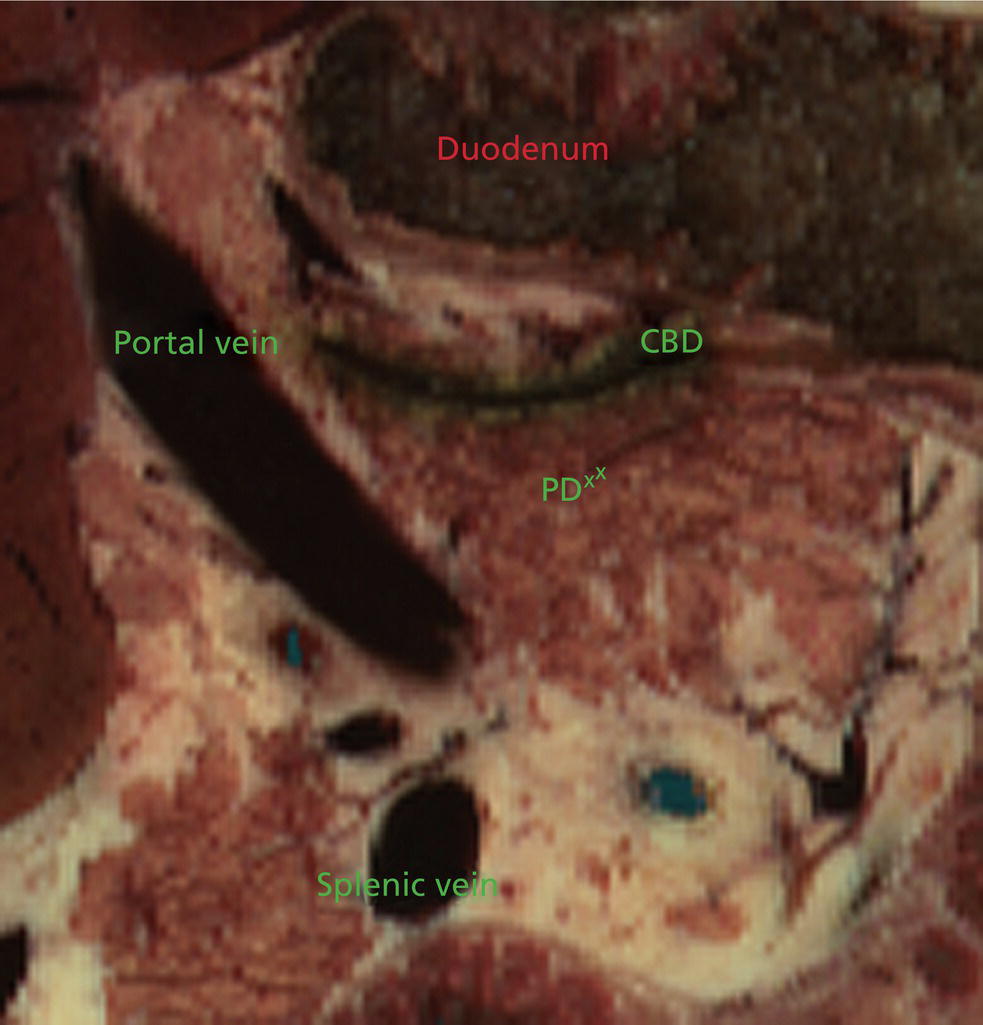
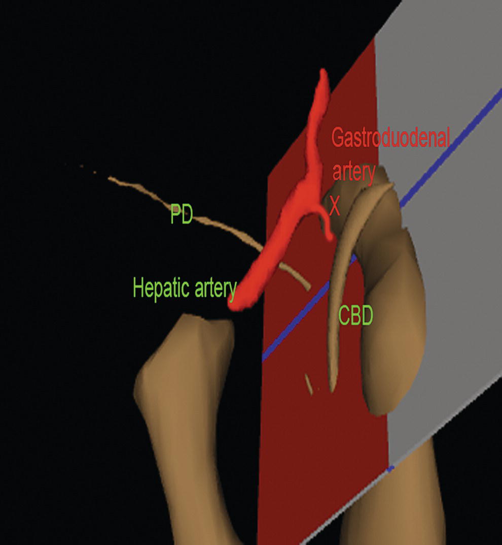
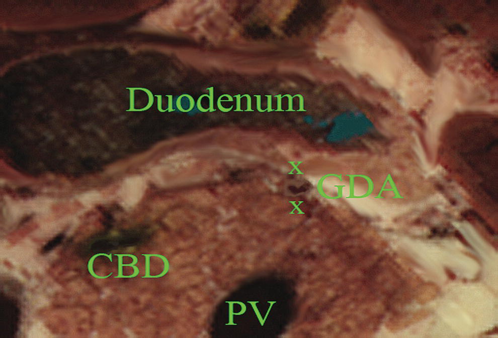
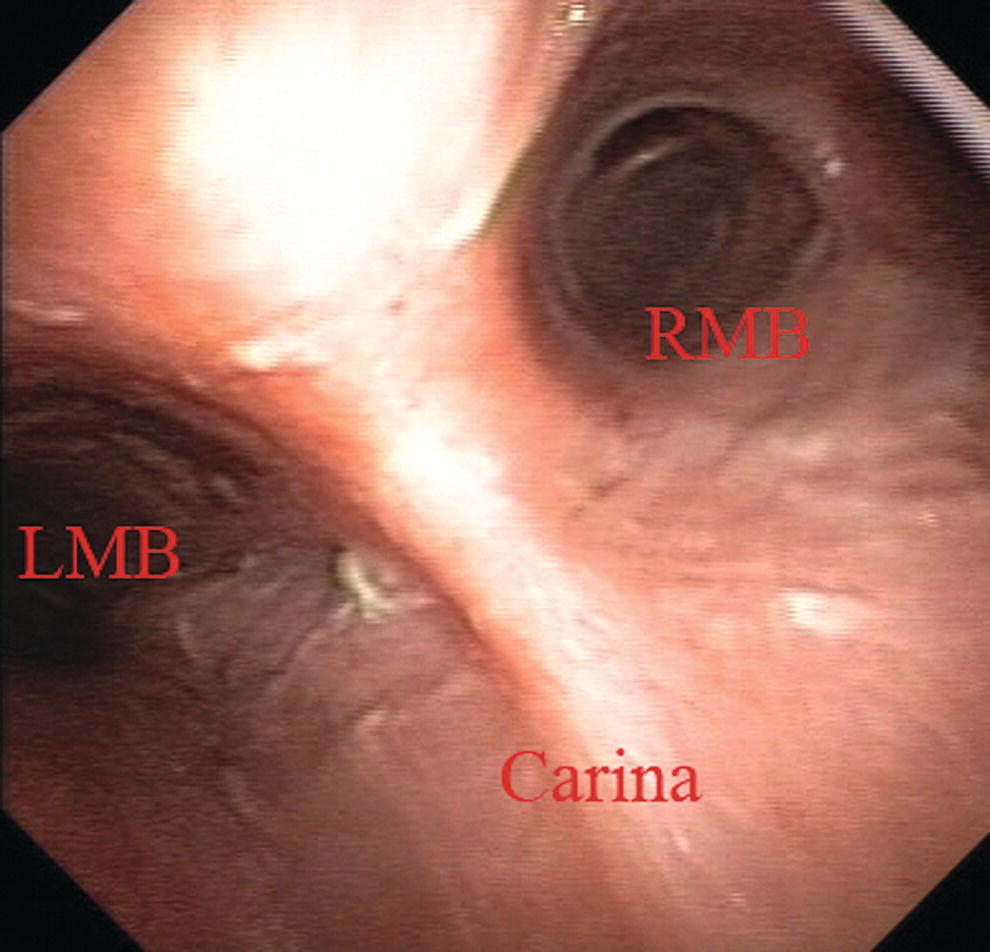
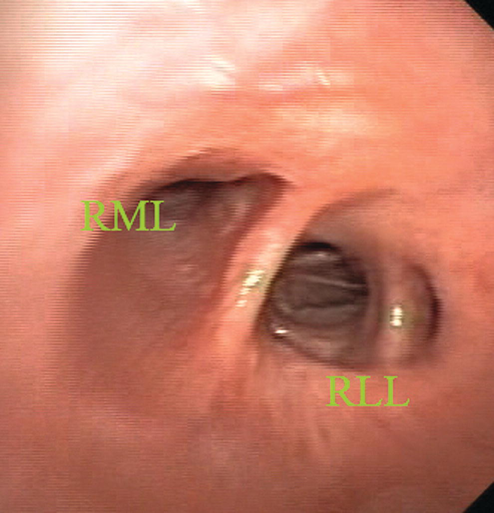
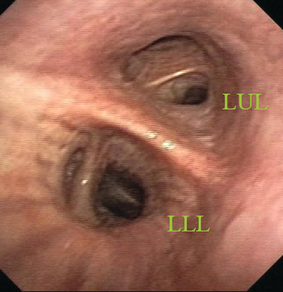
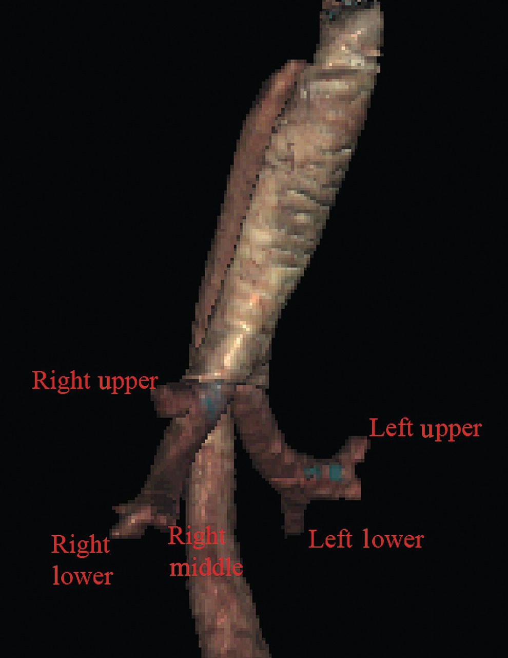
John C. Deutsch Essentia Health Care Systems, Duluth, MN, USA The Visible Human Project at the University of Colorado has generated large volumes of human anatomy data. The original information is captured by slowly abrading away frozen human cadavers in a transaxial manner and capturing the anatomy by digital imaging. The digital data is compiled and then over the years is manipulated by scientists at the University’s Center for Human Simulation to allow access to identified cross‐sections in any plane as well as to models which can be lifted from the data set. Details regarding the Visible Human Project and its applications to gastroenterology and endosonography have been previously described. This atlas is fortunate to be able to use the interactive anatomy resources developed by Vic Spitzer, Karl Reinig, David Rubenstein, and others to create movies that help explain what takes place during endoscopic ultrasound (EUS) evaluations. Since EUS is a “real‐time” examination, it seems reasonable to present this section primarily as “real‐time” videos. The videos can be viewed over and over, allowing endosonographers to look not only at the highlighted structures, but also at structures they might visualize during EUS that are not specifically identified on the selected video. This chapter uses the terms “radial array orientation” to describe planar anatomy which would be found perpendicular to a line going through the digestive tract (as would be generated by a radial array echoendoscope, Figure 1.1) and “linear array orientation” for planar anatomy generated parallel to a line going through the digestive tract (as would be generated by a linear array echoendoscope, Figure 1.2). Video 1.1 starts with Visible Human Models of the left atrium (purple), trachea and bronchi (light blue), aorta and pulmonary arteries (red), vena cava (dark blue), and the esophagus (brown). A plane is shown passing through the esophagus. This plane contains the transaxial cross‐sectional anatomy images which then follow, starting in the oropharynx and going caudally. The upper esophageal sphincter (UES) is identified. As the images proceed distally, the trachea and esophagus can be followed to a point where the brachiocephalic left carotid and left subclavian arteries are evident just above the aortic arch. Below the aortic arch is the aortopulmonary window. The azygos arch can be seen exiting the superior vena cava (SVC). This occurs just above the tracheal bifurcation. The esophagus (labeled as “E”) is surrounded by the descending aorta, the vertebrae, and the trachea. The thoracic duct (not labeled) is visible between the aorta and vertebrae, inferior to the esophagus. Going distally, the pulmonary artery becomes prominent. The region between the right mainstem bronchus (RMB) and left mainstem bronchus (LMB) is the subcarinal space. The video progresses to a level where the left atrium surrounds the superior aspect of the esophagus and then the video ends as the esophagus passes the gastroesophageal junction. An image plane cross‐section taken from a radial array orientation at the level of the subcarinal space is shown in Figure 1.3. Video 1.2 starts with the same models as above (the left atrium [purple], trachea and bronchi [light blue], aorta and pulmonary arteries [red], vena cava [dark blue], and the esophagus [brown]). The plane shows potential ways that cross‐sectional anatomy can be generated. The video then shows a sagittal image with the descending aorta inferior to the esophagus, much as what is done during linear array EUS. In this orientation the pulmonary artery (PA) and left atrium are superior. The image plane is rotated to bring the left atrium and pulmonary artery to the inferior side of the esophagus. The models are then shown again, and the plane is moved in the caudal and cephalad directions, much as during EUS. Figure 1.1 Visible Human Model of esophagus, stomach, and duodenum. The green circle shows a plane perpendicular to the axis and is similar to a plane developed during radial array endosonography. Endoscopic ultrasound of the stomach differs from EUS at other sites since the stomach does not constrain the endoscope tightly. It is important to follow anatomical structures (such as in a station approach) to avoid getting lost. The video shows models of the stomach, esophagus, duodenum, gallbladder, pancreas (brown), the aorta, splenic artery, hepatic artery and left gastric artery (red), adrenal glands (pink), and splenic, superior mesenteric veins (dark blue) as viewed from behind. A plane is passed that is similar to the image plane generated during radial array EUS. The resultant cross‐sectional anatomy starts at the level of the gastroesophageal junction, with the aorta and inferior vena cava (IVC) labeled. The aorta (which is collapsed) is followed, which brings the pancreas and left adrenal gland into view. The first artery that comes off the aorta in the abdomen is the celiac artery. There is a trifurcation into the splenic, hepatic, and left gastric arteries (LGA), although the LGA is generally smaller and difficult to see. It is shown in the video at the “x” just before the bifurcation into the celiac and hepatic arteries as identified. Figure 1.2 Visible Human Model of esophagus, stomach, and duodenum. The red circle shows a plane parallel to the axis and is similar to a plane developed during linear array endosonography. Figure 1.3 Transaxial cross‐section of digital anatomy taken at the level of the subcarinal space. Ao, aorta (both ascending, superior in the image, and descending, inferior in the image, are shown); Az, azygos vein; PA, pulmonary artery; RMB and LMB, right and left mainstem bronchi; SVC, superior vena cava. The superior mesenteric artery (SMA) comes off the aorta just distal to the celiac artery. Various endoscope maneuvers can be used to bring the portal confluence into view, and then the splenic vein can be used as a guide to visualize the pancreas body, left adrenal, kidney, and spleen. The diaphragm can be easily imaged between the kidney and the vertebrae. The linear array exam also follows the aorta to the stomach, but, as shown Video 1.4, the image plane across the pancreas is generally obtained through a sweeping motion. The first major gastric landmark is the origin of the celiac artery and SMA from the aorta (Figure 1.4). The superior mesenteric vein (SMV), portal vein, and splenic vein can be used as guides to go back and forth across the pancreas and in the process, the left adrenal, kidney, and spleen can be seen. The splenic artery runs roughly parallel to the splenic vein, but is generally tortuous. Figure 1.4 Sagittal cross‐section of digital anatomy at the level of the gastroesophageal junction, similar to a view seen during linear array endoscopic ultrasound (EUS). The celiac and superior mesenteric arteries (SMA) are shown at their insertion into the aorta. The renal vein (RV) is shown adjacent to the SMA and the splenic vein is shown adjacent to the pancreas. The radial array EUS examination through the duodenum follows a constrained path, but the endoscope can be rotated to put various structures into the inferior aspect of the image plane, as shown in the models of the duodenum, pancreas (brown), portal and superior mesenteric veins (blue), aorta (red), and SMA (silver). There are many structures of interest in a rather small area, and most of the images obtained are from the posterior view, with the liver to the right and the pancreas to the left of the image screen. After leaving the pylorus, the pancreas can be oriented with the tail pointed either to the left or inferiorly, and the splenic vein runs in the same direction as the pancreas. Going through the duodenal bulb, the gastroduodenal artery (GDA) often appears. Without Doppler, the GDA can be confused with the common bile duct (CBD) since these structures are nearly parallel in orientation and are very close to each other. As the apex of the duodenal bulb is reached, the image plane captures a longitudinal view of the CBD and the portal vein. As the descending duodenum is reached, the bile duct is seen in cross‐section and the IVC comes into view. As the third part of the duodenum is reached, the image plane rotates in such a way as to give a longitudinal cut through the IVC and then passes underneath the junction of the SMA with the aorta. Branches of the SMV can be found and the renal vein is visible in the “armpit” formed at the insertion of the SMA into the aorta. A special area is then highlighted in Video 1.5. Models show how the gastroduodenal artery and the hepatic artery (in red) relate to the CBD (in orange). Figure 1.5 shows a model with an image plane and Figure 1.6 shows the resultant planar anatomy, which forms the stack sign – a phenomenon in which the portal vein, CBD, and main pancreatic duct are captured in the same field. The linear array exam of the duodenum is an excellent way to see the CBD and pancreatic head. The anatomy is difficult to understand since the endoscope image is tipped into the C‐sweep of the duodenum, and then the image plane is swept in various angles, resulting in a cross‐sectioning of the CBD and pancreatic duct (PD). The image planes employed can be appreciated from observing the models in the video. The cross‐sections obtained can be positioned to first give a longitudinal view of the CBD and both longitudinal views and cross‐sections of the portal vein and SMV. Figure 1.5 Visible Human Model of an image plane that is in the location in which radial array endoscopic ultrasound (EUS) generates the “stack sign”, in which the portal vein, common bile duct (CBD), and pancreatic duct are in the same field. A probe in orange is shown going into the proximal duodenum. The superior mesenteric vein (SMV) is also shown. Figure 1.6 The cross‐sectional anatomy within the plane shown in Figure 1.3. The common bile duct (CBD), pancreatic duct (PD), and portal vein are all in the same field (“stack sign”). Figure 1.7 Visible Human Model with a plane that is in a location similar to what can be generated during linear array endoscopic ultrasound (EUS), showing the relative position of the gastroduodenal artery, pancreatic duct (PD), hepatic artery, and common bile duct (CBD). As seen in the first part of Video 1.6, if the endoscope is in the second part of the duodenum, the bile duct goes to the ampulla away from the transducer and the liver is towards the transducer. If the endoscope is in the duodenal bulb, as shown in the second part of the video, the liver is away from the transducer. The GDA drapes over the portal vein and can be found most readily using Doppler. Figure 1.7 shows a model and Figure 1.8 the resultant cross‐section where the GDA can be found. Video 1.7 shows models of various male pelvic structures, starting with the rectum and sigmoid colon, the aorta, and the iliac arteries with internal and external branches. The SMA is included to show the anterior direction of the models. The prostate, bladder, coccyx, and sacrum are added sequentially. A second set of models is then shown which contains the rectum, sigmoid colon, prostate, bladder, coccyx, sacrum, external iliac arteries (red), veins (blue), as well as three‐dimensional models of the internal and external anal sphincters. The sphincters and sigmoid colon are then removed. Planar anatomy in the radial array orientation from the male rectum is then shown, starting distally and moving proximally. The anal sphincters are labeled, followed by the prostate, urethra, levator ani, and coccyx. The sacrum and seminal vesicles are then shown, followed by the right internal iliac artery. Figure 1.8 Cross‐sectional anatomy generated within the plane shown in Figure 1.5. The gastroduodenal artery (GDA) and common bile duct (CBD) are shown with the pancreatic head. The portal vein (PV) is shown near the portal confluence. Video 1.8 starts distally at the end of the anal canal. The internal and external sphincters are shown, and residual stool is present in the rectum. Moving proximally, the vagina and urethra are shown, followed by the cervix and bladder. Video 1.9 starts with a sagittal plane through the pelvis with the body facing the left. The prostate, rectum, anal canal, and bladder are identified. The plane is rotated, and the seminal vesicles and internal anal sphincter are labeled. The coccyx and sacrum are apparent at the start and end of the video but are unlabeled. Video 1.10 starts with a sagittal plane through the pelvis with the body facing the left and slightly face down. The anal canal, rectum, uterus, and bladder are identified. Stool is present in the rectal vault. The plane is rotated, and towards the end of the video the internal anal sphincter (IS) and external anal sphincter (ES) are identified. Video 1.11 shows models of some of the main arteries that are visualized during endosonography. A close‐up view shows the celiac artery with its branches (hepatic, splenic, and left gastric arteries). The gastroduodenal and pancreaticoduodenal arteries are shown coming off the hepatic artery. The internal and external iliac arteries are then identified, followed by identification of the arteries associated with the aortic arch (left subclavian, left carotid, brachiocephalic) and the branches of the brachiocephalic (right subclavian and right carotid). Various organs are then placed in the model starting with the esophagus, then pancreas, stomach, and duodenum. Some of the major veins visualized during endosonography are shown. At first, the vena cava and right atrium are identified, after which, the renal veins and azygos veins are added. The portal system with the portal vein, SMV, splenic vein, and inferior mesenteric vein (not labeled) are placed in blue. The systemic veins are then colored and removed. The pancreas is placed on the portal vein and its branches, showing how the head runs parallel to the SMV and the tail runs parallel to the splenic vein. Extratracheal anatomy is similar to extraesophageal anatomy and many of the structures seen in the extratracheal spaces are the same as what is seen in the extraesophageal spaces. The endoluminal views of the trachea are oriented so that the membranous trachea is inferior and is splayed wider than the cartilaginous trachea at the level of the carina, putting the right mainstem bronchus (RMB) to the right and the left mainstem bronchus (LMB) to the left (Figure 1.9). As one goes right the bronchus immediately branches superiorly towards the right upper lobe (RUL), and continues straight as bronchus intermedius (BI) (Figure 1.10), which then branches towards the right middle lobe (RML) and right lower lobe (RLL) of the lung (Figure 1.11). Going left from the carina, one goes down the relatively long left mainstem bronchus until it branches towards the left upper lobe (LUL) and left lower lobe (LLL) of the lung (Figure 1.12). An overview of the bronchial tree is shown in Figure 1.13. Video 1.13 starts with the cervical trachea. All images are in a linear array orientation as endobronchial ultrasound (EBUS) is exclusively linear. The esophagus is inferior and the brachiocephalic artery and vein are superior. The video begins with rotation of the image plane. The superior part of the plane moves left and the inferior part moves right. This moves the esophagus out of view and brings the left subclavian artery and left carotid artery into the inferior part of the image. Eventually, the esophagus is seen in the superior part of the image and, with continued motion, the esophagus again appears inferior to the trachea. At this point, the image plane moves caudally to the carina. The right pulmonary artery, brachiocephalic artery (BA), and left brachiocephalic vein (LBV) are labeled. The plane is again rotated to splay the right (RMB) and left (LMB) mainstem bronchi apart. The plane is then moved to better visualize the right mainstem bronchus, showing the branch to the right upper lobe (RUL), the azygos arch (AzArch), the bronchus intermedius (BI). This same plane shows the relation of the aortic arch (AoArch) and left pulmonary artery to the left mainstem bronchus (LMB). As the plane goes down the right mainstem bronchus/bronchus intermedius (RMB) towards its next bifurcation, the azygos arch (AzAr), right pulmonary artery (RPA), and right pulmonary vein (RPV) are shown. Figure 1.9 Endobronchial view of the carina, showing the right (RMB) and left (LMB) mainstem bronchi. Figure 1.10 Endobronchial view of the first branch of the right mainstem bronchus towards the right upper lobe (RUL) and the bronchus intermedius (BI). Figure 1.11 Endobronchial view of the bifurcation of the bronchus intermedius towards the right middle lobe (RML) and the right lower lobe (RLL). Figure 1.12 Endobronchial view of bifurcation of the left mainstem bronchus towards the left upper lobe (LUL) and left lower lobe (LLL). The plane is brought back to the carina to visualize the left mainstem bronchus (LMB), and the azygos arch (AzAr), aortic arch (AoAr), left pulmonary artery (LPA), and vein (LPV) are identified. The branching to the left upper lobe (LUL) and left lower lobe (LLL) are shown, and the aorta (Ao) and left pulmonary artery are labeled. Figure 1.13 A Visible Human Model of the bronchial tree.
1
Normal Human Anatomy
Introduction
Normal EUS anatomy from the esophagus
Radial array orientation (Video 1.1)
Linear array orientation (Video 1.2)
Normal EUS anatomy from the stomach
Radial array orientation (Video 1.3)

Linear array orientation (Video 1.4)
Normal EUS anatomy from the duodenum
Radial array orientation (Video 1.5)
Linear array orientation (Video 1.6)
Normal EUS anatomy from the rectum
Radial array orientation, male (Video 1.7)
Radial array orientation, female (Video 1.8)
Linear array orientation, male (Video 1.9)
Linear array orientation, female (Video 1.10)
Vascular videos
Arterial (Video 1.11)
Venous (Video 1.12)
Endobronchial ultrasound anatomy (Video 1.13)

Related posts:
 How to do EUS‐guided Radiofrequency Ablation of Pancreatic Neuroendocrine Tumors
 Biliary Tract Pathology
 How to Inject Chemotherapeutic Agents
 How to do EUS‐guided Treatment of Gastric Varices
 How to use ex vivo Models in Teaching Therapeutic Endoscopic Ultrasound
 How to Perform Endoscopic Ultrasound‐directed Transgastric Endoscopic Retrograde Cholangiopancreatography (EDGE)
Stay updated, free articles. Join our Telegram channel

Full access? Get Clinical Tree


