Chapter 1 OPTIMIZATION OF CLINICAL MUSCULOSKELETAL IMAGING
MAGNETIC RESONANCE IMAGING
High-Field versus Low-Field Scanners
Scanners come in a variety of field strengths, and options are available for various gradient strengths and slew rates intended to optimize scanning. Software options are often available at additional cost. These issues can cause confusion when selecting a scanner for purchase. In addition, different manufacturers have different terminology for sequences, magnet homogeneity, and other physical features that make it difficult to perform an “apples to apples” comparison. However, rarely does musculoskeletal imaging come into consideration when purchasing a scanner. Typically, neurologic and body imaging applications are those that guide scanner selection and purchase, and musculoskeletal imaging is a secondary consideration. A basic understanding of MR physics principles is generally all that is needed to optimize musculoskeletal imaging protocols, no matter what machine is used. The differences between high-field and low-field scanners are extremely important in musculoskeletal imaging; advantages and disadvantages are summarized in Table 1-1.
Table 1-1 Low-Field MRI: Advantages and Disadvantages
Without fat suppression on T1-weighted images, visualization of intravenously or intra-articularly administered contrast can be difficult, limiting applications such as tumor/infection imaging and MR arthrography. Also, there is relatively lower signal overall. To compensate, this requires increasing the number of signal averages to increase signal at the expense of increased imaging time, which can increase motion artifact in the extremities. Length of examinations is generally much greater on low-field scanners and may not be as useful for uncooperative patients. Coil options are often limited on low-field scanners, with a small variety of multipurpose surface coils available for imaging various musculoskeletal structures. This can result in an inappropriately large field of view and low resolution.
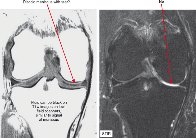
Nevertheless, there are some advantages to musculoskeletal imaging on low-field scanners. T1 contrast is actually superior to that of high-field scanners, although this is a relatively minor advantage in practice; in fact, improved T1 contrast can be disadvantageous. Consider evaluation of the knee on a low-field system; on a T1-weighted sequence fluid may appear black, blending with signal of the menisci (Fig. 1-1). Because of lower field strength, artifact from metal may be decreased compared with high-field scanners, and imaging patients who have prostheses, screws, or other orthopedic hardware can actually be improved by directing these patients to a low-field scanner. Keep in mind that advances in gradient technology at high fields have offset many of these advantages for high-field scanners. Chemical shift artifact is also decreased at low field.
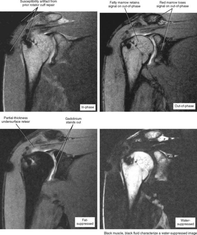
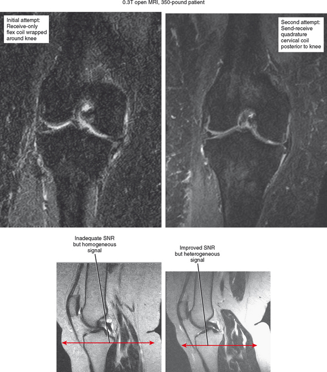
Moreover—and what is possibly the most important consideration—is the gantry size and table weight limit of low-field scanners, which generally offer an open environment and a weight limit of up to 500 pounds. For obese patients, no other imaging options may be available. This is mainly an issue in the United States. Regarding fat suppression, many low-field scanners offer a software option based on the Dixon technique, which acquires an in-phase and out-of-phase image, and through subtraction post-processing, obtains a fat-suppressed image (Fig. 1-2). If the subtraction is performed from images acquired in the same series no subtraction errors occur, and the images and degree of fat suppression are generally excellent. In fact, if the radiologist’s intention is to perform MR arthrography on a low-field scanner, strong consideration should be given to acquiring this post-processing software. Newer generations of low-field scanners can actually separate the fat and water peaks, performing true fat saturation, but this has been suboptimal compared with the Dixon technique.
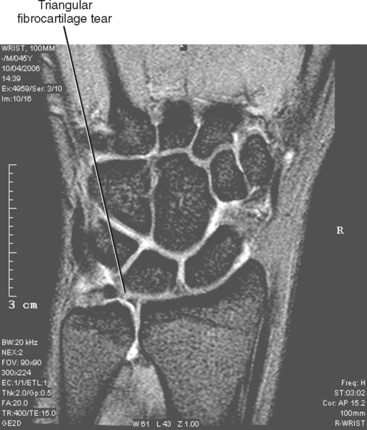
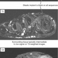
Extremity scanners are also available, which are generally low field at about 0.2 T; although they are low cost and provide a high degree of patient comfort, low image quality corresponds to the low strength. Also, the narrow bore of the magnet limits scanning to wrists/hands, elbows, ankles/feet and knees. However, a 1.0 T extremity scanner is available that provides good image quality comparable to that achieved with closed 1.5 T scanners (Fig. 1-3). Other open configuration 1.0 T scanners are also available.
Advantages and Disadvantages of 3 T Scanners for Musculoskeletal Imaging
There are some distinct advantages of 3 T MRI for musculoskeletal imaging. The high field strength provides high SNR over all imaging sequences, allowing an increase in the matrix, a decrease in slice thickness, and a decrease in field of view, providing increased resolution; ultimately, high resolution is a major key to success in musculoskeletal radiology (Fig. 1-4). Alternatively, one can use the signal surplus to decrease number of excitations (NEX), thereby shortening examination time and increasing patient throughput. However, protocols must be altered somewhat to account for the different physical properties of the 3 T environment. For example, the high field strength at 3 T accentuates susceptibility artifact from metal, limiting evaluation of orthopedic hardware. In addition, chemical shift artifacts may be increased, resulting in black-white effect at fat–water interfaces. This can be eliminated if fat suppression is used; alternatively, one can make the pixels smaller to reduce this artifact by increasing matrix or decreasing the field of view. Manipulation of the receiver bandwidth is a third strategy that can be used to address the problem.
Coils
Although an understanding of MR imaging physics and basic sequence optimization is essential, purchasing a wide range of coils is the easiest way to optimize musculoskeletal imaging (Fig. 1-5), regardless of scanner type. Unlike coils designed for the abdomen, head, and spine, there is a tremendous degree of variation in configuration and quality of various surface coils used for extremities. A rule of thumb is that the smallest coil possible should be used for imaging an extremity to achieve the desired field of view (Box 1-1). Basically, the coil is analogous to an ear trying to hear a faint noise coming from the body part being imaged. The farther the ear is from the body part, the softer the noise (i.e., weaker the signal) will be. Therefore, the more closely the coil fits against the body part, the better the images will be. It follows that an extremity coil used for the knee will not be as optimal for imaging the ankle, which is smaller and not cylindrically shaped.


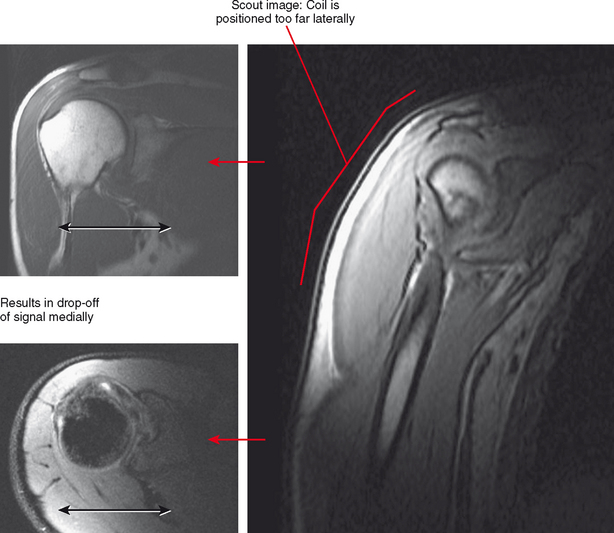
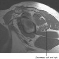
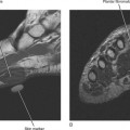
Occasionally, patient limitations require an alternate coil configuration. For example, it is optimal to image the elbow above the head in an extremity coil, but this position may be difficult for patients to achieve, particularly those who have shoulder problems. A reasonable alternative would be imaging the arm at the side wrapped in a flex coil; at least the patient will be able to tolerate the examination with less motion. Similarly, some newer shoulder coil configurations are fitted to shoulder shape, but this can also create drawbacks. A shoulder coil design that is cuplike may not fit all patients, resulting in field cut-off (Fig. 1-6). This may also not allow positional imaging, such as the abduction–external rotation (ABER) position.
IMAGING SEQUENCE SELECTION
Spatial Resolution versus Contrast—Which to Choose?
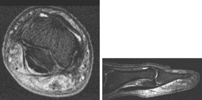
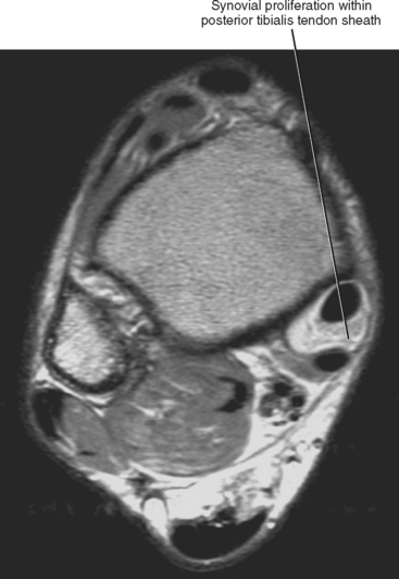
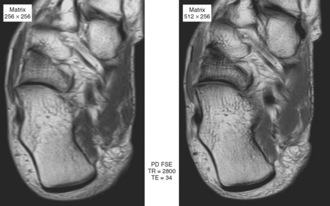
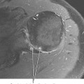
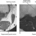
Sequences that offer high spatial resolution are useful for evaluating small structures, such as interosseous ligaments of the wrist and the labrum of the hip, or for evaluation of the articular cartilage. These sequences require high SNR, allowing the radiologist to decrease field of view and increase matrix size. Gradient-echo imaging (see Fig. 1-3) can provide high in-plane and out-of-plane resolution; in-plane resolution is related to SNR, field of view, and matrix (i.e., discrimination of adjacent structures in the X/Y plane), and out-of-plane resolution is related to slice thickness and interslice gap. Three-dimensional gradient sequences can be acquired at very narrow slice thickness, without a gap. Proton density imaging provides high SNR, since fat and fluid both have high signal (Fig. 1-7). This added signal can be used to decrease field of view and increase image matrix size, thus increasing spatial resolution (Fig. 1-8).
Sequences with high contrast resolution provide a large difference in signal between the anatomic structures being imaged and the surrounding tissues. For example, a fat-suppressed T2-weighted image of the wrist has high contrast resolution, with fluid being very bright and the triangular fibrocartilage being very dark. STIR imaging has high contrast, but may be limited by lower spatial resolution. One way to increase contrast resolution is to perform MR arthrography using fat-suppressed T1-weighted images (Fig. 1-9), which, when performed with spin-echo or gradient-echo imaging, also can be optimized for spatial resolution. This is one advantage for performing MR arthrography for internal derangement. Although it may be desirable to combine high contrast and spatial resolution, often these cannot be achieved in the same sequence, and protocols should be set up with some sequences optimized for spatial resolution (high matrix, small field-of-view proton density for gradient-echo imaging) and others designed for high contrast (fat-suppressed T2-weighted imaging or STIR). Newer scanners provide an estimate of SNR when changing sequence parameters from the standard settings, allowing the technologist to alter those parameters to adjust SNR to a satisfactory level. This can take some of the guesswork out of protocol management.
FAST SPIN-ECHO IMAGING
When using fast spin-echo imaging, care should also be taken to avoid blur artifact. This is less of a consideration in newer scanners, but can still be seen with a combination of a high echo train length and low TE. In this situation, the low selected TE is used to plot the center of K space (resulting in contrast at the desired TE), whereas the higher TEs, which are low in amplitude, are used for the periphery of K space (which determines image sharpness). The low amplitude of the TEs used for resolution results in lack of sharpness of the image, or blur artifact. For this reason, some authors have suggested that fast spin-echo imaging should not be used for proton density imaging, such as for evaluation of the knee menisci. However, if the echo train length is limited to 4 and TE is not below 20 msec, this artifact is generally not noticeable. In addition, the use of a higher receiver bandwidth setting to reduce the interecho spacing will reduce blurring artifacts: 20- to 24-kHz bandwidth settings on gradient echo and 150- to 200-Hz/pixel settings on Siemens; and 1 to 1.5-pixel shift on Philips equipment work well. Fast spin-echo imaging can even be used to acquire T1-weighted images. At such a low TE, the echo train length must be decreased further, generally to 2 echoes.
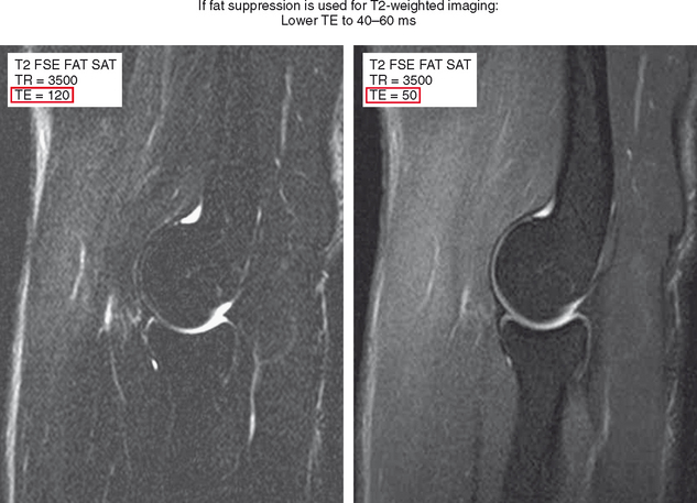
Another common mistake is using similar parameters that were historically used for T2-weighted spin-echo imaging for fast spin-echo imaging, which results in unsatisfactory images. When spin-echo technique is used to acquire T2-weighted images, a TE of 100 to 120 msec is used to achieve high fluid conspicuity. Fast spin-echo imaging with fat suppression at the same TE results in a very black-and-white image with low SNR and a grainy appearance. The recommended TE for T2-weighted fast spin-echo fat-suppressed images is about 40 to 60 msec (Figs. 1-10 and 1-11). Although this borders on proton density imaging parameters, lowering the TE recaptures signal and provides a high-quality anatomic image while retaining fluid conspicuity. As long as all these factors are taken into consideration, fast spin-echo imaging can be used to acquire both high spatial resolution proton density images, in addition to high-contrast fat-suppressed T2-weighted images for evaluation of the musculoskeletal system (Table 1-2).
| Increase | Decrease |
|---|---|
| Advantages | |
| Increased fluid brightness | Recapture signal-to-noise ratio (SNR) |
| Reduce blur artifact | Reduce metal artifact |
| Disadvantage | |
| Lose SNR | Decreased fluid brightness |
SHORT TAU INVERSION RECOVERY
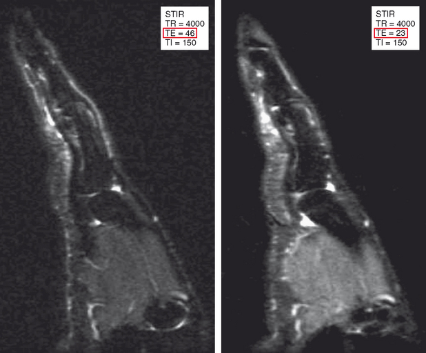
STIR imaging is like the bone scan of MRI—very sensitive but with relatively low resolution. The STIR sequence incorporates a 180-degree inversion pulse followed after a certain time interval (the inversion time, TI) by a spin-echo or fast spin-echo sequence. After the 180-degree pulse, protons in different tissues relax through the transverse plane at different rates. The tissue crossing the transverse plane gets dephased by the 90-degree pulse that initiates the rest of the sequence, and the result is no signal from that tissue. Selection of the inversion time is generally based on relaxation of fat through the transverse plane to achieve a fat-suppressed image. Because T1 relaxation rates are different at different field strengths, the inversion time also must be adjusted at different field strengths. Table 1-3 lists optimal inversion times at various field strengths. STIR imaging can be acquired at any field strength and is particularly advantageous at low field strengths, where other forms of fat suppression are limited. STIR also is useful at higher field strengths when using a large field of view (Fig. 1-12
Stay updated, free articles. Join our Telegram channel

Full access? Get Clinical Tree


