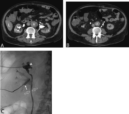
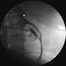
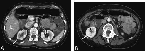
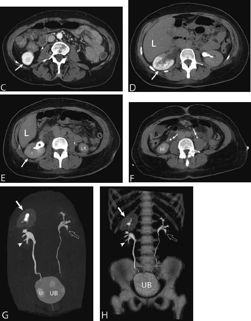
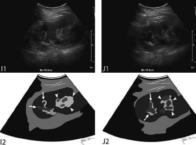
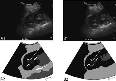
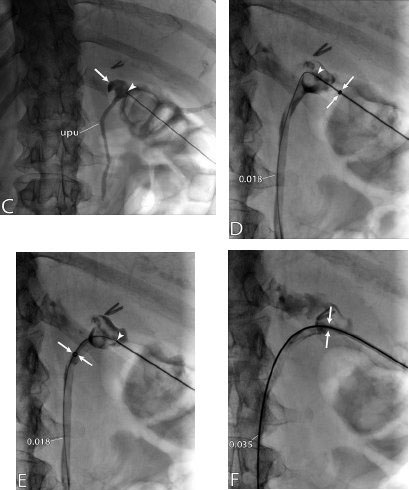
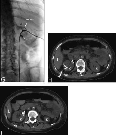
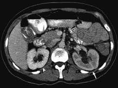
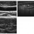
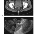
11 Percutaneous Nephrostomy The following is generally the order from the most common indication to the least common indication for a percutaneous nephrostomy. Notice that there is no mention of hydronephrosis. Hydronephrosis is not an indication to percutaneous nephrostomy. Hydronephrosis is not synonymous with urinary obstruction and urinary obstruction does not necessarily lead to hydronephrosis. Acute high-grade urinary obstruction shuts down the kidney’s ability to form urine; thus, it does not lead to the backing-up of urine to cause enlargement/engorgement of the pelvicalyceal system by urine. Dilation of the pelvicalyceal system can be seen for months after an obstruction has been resolved. In addition, there are several causes of nonobstructive hydronephrosis: Fig. 11.1 Duplicated collecting system. (A) Delayed contrast enhance (pyelogram phase) axial computed tomography (CT) image of the midabdomen at the level of the renal pelvis. The left kidney (LK) exhibits a duplicated collecting system. The arrowhead points to the upper moiety (upper pole) ureter, which passes adjacent to the lower moiety renal pelvis (arrow) that is leading to a separate ureter (L, liver; RK, right kidney; LK, left kidney; I, inferior vena cava; A, abdominal aorta). (B) Delayed contrast-enhanced (pyelogram phase) axial CT image at a lower level than in Fig. 11.1A. The left kidney (LK) exhibits a duplicated collecting system. There are two separate ureters (arrowhead: upper moiety; arrow: lower moiety). If they both continue separately to the urinary bladder then it is a complete duplication. If they fuse, then this is a partial duplication. This is a complete duplicated collecting system (not shown) (RK, right kidney; LK, left kidney; I, inferior vena cava; A, abdominal aorta). (C) Fluoroscopic image of the same patient as Figs. 11.1A and 11.1B demonstrating a nephrostomy tube in each moiety (arrowhead: upper; arrow: lower) of the completely duplicated collecting system. The hollow arrows point to the upper moiety ureter. The lower moiety ureter is not seen. The ureters do not fuse. The purpose of this image is not to show complete ureteric separation, but to show the requirement of the two nephrostomy tube placements. Fig. 11.2 Fluoroscopic image during a nephrostogram demonstrating a partially duplicated collecting system. The upper moiety (arrowhead) does not have a nephrostomy tube. The nephrostomy tube is in the lower moiety collecting system (arrow) and drains both moieties because their ureters fuse close by the renal pelvises (hollow arrows). The only stipulation for the system to be drained by one nephrostomy tube is that the proximal ureters be patent. Fig. 11.3 (A,B,C) Duplicated collecting system with upper moiety obstruction. Contrast-enhanced (nephrogram phase) axial computed tomography (CT) images through the upper, mid-, and lower portions of the right kidney. These images are to be compared with the delayed images (pyelogram phase) in Figs. 11.3D, 11.3E, and 11.3F. There is slight hydronephrosis of the upper pole moiety (Fig. 11.3A, arrowhead) compared with the lower pole moiety (Fig. 11.3B, arrowhead). In addition, there is a slight delay in the nephrogram phase of the upper moiety (Fig 11.3A, arrow) compared with the lower moiety (Figs. 11.3B and 11.3C, arrows) (L, liver; Sp, spleen). (D,E,F) Delayed contrast-enhanced (pyelogram phase) axial CT images through the upper, mid-, and lower portions of the right kidney. These images are to be compared with the earlier images (nephrogram phase) in Figs. 11.3A, 11.3B, and 11.3C. There is a delay of the nephrogram of the upper pole moiety (Fig. 11.3D, arrow). The upper pole is still in the nephrogram phase (Fig. 11.3D, arrow) compared with the lower pole moiety (Figs. 11.3E and 11.3F, arrow). The lower moiety is well within the pyelogram phase with contrast in the lower moiety renal pelvis (asterisk, Fig. 11.3E). In Fig. 11.3F, the contrast is seen in the left singular ureter and the right lower moiety ureter (arrows) (L, liver; RK, right kidney; LK, left kidney). (G,H) Maximum intensity projection (MIP; Fig. 11.3G) and a three-dimensional reconstruction (Fig. 11.3H) of the same CT examination partly shown in Figs. 11.3A–11.3F); both demonstrating the singular renal collecting system on the left (hollow arrow) and the duplicated collection system on the right (solid arrow in the upper moiety; arrowhead in the lower moiety). The left collecting system (hollow arrow) and the lower moiety right collecting system (arrowhead) are synchronized (same contrast phase). However, the obstructed upper moiety on the right (solid arrow) is delayed and is still in the nephrogram phase. Notice the shadow of a ureterocele (U) in Fig. 11.3G inside the urinary bladder (UB). Remember, “Vowels stay together and constants stay together” – Upper pole: Obstructed, Ectopic, Ureterocele, enters bladder Inframedial Lower pole: Reflux, Dominant (drains larger renal mass), enters bladder supralateral. (I,J) Gray-scale ultrasound images (top) and schematic sketches (bottom) of the same duplicated system on the right side. Again noted is the mild hydronephrosis in the upper pole moiety (arrows) compared with the lower moiety (arrowheads). Fig. 11.4 (A,B) Nephrostomy tube placement in duplicated collecting system with upper moiety obstruction. Gray-scale ultrasound images (top) and schematic sketches (bottom) of the same duplicated system as in Fig. 11.3. A 21-gauge needle (arrowhead at needle tip) has been passed under real-time ultrasound guidance into the upper pole collecting system (between arrows). (C) Fluoroscopic image during the initial antegrade pyelogram after the 21-gauge needle (arrowhead at needle tip) has been passed under real-time ultrasound guidance into the upper pole collecting system (arrow). As can be seen, the upper pole collecting system is small (nondominant), which is typical, and leads to the independent (totally separated upper pole ureter: upu). (D,E) Fluoroscopic images obtained after a 0.018-inch wire (0.018) has been passed coaxially through the 21-gauge access needle. The 21-gauge needle has been removed and replaced with an AccuStick (Boston Scientific, Natick, MA) dilator system over the 0.018-inch wire. The arrowhead does not point to the access needle tip (the needle has been removed), but it points to the tip of the inner metal stiffener of the AccuStick system. The outer dilator of the AccuStick system has a radiopaque ring/marker (between arrows). The tip of the metal stiffener (arrowhead) is stopped short of the 0.018-inch wire turn (metal does not go around corners). At this time (Fig. 11.4D), the operator passed the plastic/dilator portion of the AccuStick system over the wire and metal stiffener to enter the distal renal pelvis/proximal ureter (Fig. 11.4E). Notice the filling defects in the collecting system and ureter (compare it with Fig. 11.4C): this is blood in the collecting system, which is not uncommon in difficult nephrostomy tube placements. (F) Fluoroscopic image obtained after the 0.018-inch wire has been exchanged for a 0.035-inch wire (0.035). The AccuStick system has also been removed. It has done its designed job, which is primarily to upsize the 0.018-inch platform (wire system) to a 0.035- or 0.038-inch wire system, and secondarily, to dilate the tract to up to 6.5-French. The AccuStick system has been replaced with an 8-French fascial dilator to dilate the retroperitoneal tract in preparation for an 8-French nephrostomy drain placement (arrows at tip of 8-French dilator). (G) Fluoroscopic image obtained after an 8-French nephrostomy drain has been placed (8-French all purpose draining locking (APDL) catheter). Because the collecting system is duplicated and the less dominant upper pole moiety is not significantly hydronephrotic, there is little room to place a wide (more than 2-cm diameter) pigtail catheter. The 2-cm pigtail catheter is formed/deformed partly in the proximal ureter (arrowhead) and partly, unraveled in the small upper pole collecting system (arrow). (H,l) Unenhanced axial CT images of the midabdomen at the level of the renal pelvis. The arrowhead and arrow correlate with the arrowhead and arrow in the fluoroscopic image of Fig. 11.4G, respectively (K, kidney; I, inferior vena cava; Ao, aorta; L, liver). Fig. 11.5 Obstruction of the kidney with delayed nephrogram (obstructive nephropathy). Contrast-enhanced axial CT image through the midportions of the kidneys. The left kidney is obstructed by a stone in the ureter (not shown). The acute obstruction has not yet developed into significant hydronephrosis; however, it has caused a delayed nephrogram in the left kidney (arrow). As can be seen, the left kidney is in an early nephrogram phase with corticomedullary differentiation. However, the right kidney (arrowhead) is in a later nephrogram phase without corticomedullary differentiation.
Indications
Contraindications
Relative Contraindication
Preprocedural Evaluation
Evaluate Prior Cross-Sectional Imaging
Evaluate Prior Nuclear Renal Scan
Evaluate Preprocedure Laboratory Values
Obtain Informed Consent
Related posts:
Stay updated, free articles. Join our Telegram channel

Full access? Get Clinical Tree


