Symptoms arise when narrowing of the spinal canal, lateral recesses, or intervertebral foramina impinge upon the neural structures that traverse the spinal column. Pathology involving the structures that make up the spine can narrow the relevant spaces. Here a description of percutaneous procedures that address narrowing from disc disease, ligamentum Flavum hypertrophy, and devices that open and stabilize the spine at individual levels are presented.
Introduction
Spinal stenosis is characterized by the narrowing of the spinal canal, lateral recesses, or intervertebral foramina, causing compression on the spinal cord and nerves. Common causes of spinal stenosis include ligamentum flavum hypertrophy, disc degeneration, osteophyte formation, and degenerative arthritis. Minimally invasive spine procedures have become increasingly popular for treating spinal conditions, providing effective alternatives to traditional open surgery. These procedures offer numerous advantages, including reduced recovery time, minimized complication rates, and improved overall patient outcomes.
1) MILD
Minimally invasive lumbar decompression (MILD) is a fluoroscopically guided procedure performed to treat spinal stenosis by removing excess ligament tissue and small pieces of bone that contributing to narrowing of the spinal canal.
Ideal candidates for this procedure are patients with symptomatic lumbar spinal stenosis secondary to hypertrophic ligamentum flavum (≥2.5 mm) confirmed on MRI and symptoms of neurogenic claudication. ,
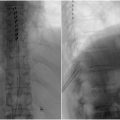
The procedure is performed with a kit comprised of a single-use 6-gauge (5.1 mm diameter) mild® portal cannula with trocar, a portal stabilizer, a bone sculptor rongeur, and a tissue sculpture (Vertos Medical Inc., Aliso Viejo, California). Following a comprehensive imaging evaluation, patient is positioned prone with a bolster, or a pillow placed under the abdomen to reduce lordosis. Fluoroscopy is used to identify the target spinal level and for visualization throughout the performance of the procedure. After administering local anesthetic, an epidurogram is obtained on the ipsilateral side to the intended treatment level to establish a baseline for assessing the epidural space, the safety depth, and visual field for the procedure as shown in Fig. 1 . Under fluoroscopy, trajectory is planned ahead so that the tip of the portal is docked at the lamina of the target level. After making a #15 blade stab incision, the MILD trocar-portal unit is inserted percutaneously and advanced along the predetermined trajectory until the distal end of the trocar touches the superior surface of the inferior lamina. A contralateral oblique view is obtained again to ensure correct placement of the unit. The trocar is removed. A MILD portal stabilizer is then used to secure the portal position and angle. The bone rongeur is introduced through the access portal to remove a small amount of the lamina, creating better access to the interlaminar space and the ligamentum flavum. Once an access is gained to the ligamentum flavum, the bone rongeur is removed, and tissue sculptor is used to resect the ligamentum flavum. A confirmatory epidurogram is performed to evaluate the improved contrast spread, indicating relieved stenosis.
2) Spacer

The Superion® Indirect Decompression System spacer gently separates the vertebrae and increases foraminal height, which help relieve neural compression secondary to spinal stenosis and improving spinal stability.
The spacer is indicated for skeletally mature patients with neurogenic claudication due to lumbar spinal stenosis, with or without grade 1 spondylolisthesis, confirmed by X-ray, MRI and/or CT that shows thickened ligamentum flavum, narrowed lateral recess and/or central canal or foraminal narrowing.
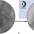
The procedure is performed with the Superion® Indirect Decompression System (Vertiflex, Carlsbad, CA, USA). Patient is placed in the prone position with a bolster placed under the abdomen to adequately flex the lumbar spine. Under fluoroscopy guidance, the intended level for treatment is identified and marked using a dilator. After administering local anesthetic, a 12-15mm midline incision is made at the midline down to the supraspinous ligament under the guidance of AP and lateral fluoroscopy. Dilator 1 is inserted into the treatment site at midline and advanced with the use of the mallet until the distal tip touches the dorsal aspect of the facet shadow. Confirmation of the depth and placement of the dilator 1 can be done via lateral and AP fluoroscopy. Once confirmed, Dilator 2 is then inserted over Dilator 1 and advanced carefully so that the Dilator channels are between the superior and the inferior spinous processes. Fluoroscopic imaging is obtained again to ensure correct placement. Dilator 1 is removed. A cannula is inserted over Dilator 2 and is advanced through the supraspinous ligament until the distal tip is firmly placed between the adjacent spinous processes and positioned slightly beyond the apexes of the spinous processes. Advancement should be done carefully to prevent Dilator 2 further advancement and the trajectory stays at the midline. Confirmatory imaging is done to verify the position, and Dilator 2 is removed. The interspinous gauge is inserted through the cannula to determine the proper implant size selection. Proper orientation of the gauge is confirmed via the orientation flat on the barrel. The depth of the gauge is confirmed with lateral fluoroscopy. The distal tips of the gauge should touch the spinous process dorsal to the spinolaminal junction of the superior aspect. A measurement of the interspinous space is read on the gauge scale after gripping the device firmly until resistance is detected at the distal tips. The gauge is locked, and midline positioning is confirmed via the AP fluoroscopic view, which shows the distal tips of the gauge contain the spinous processes. The gauge is removed. The appropriate implant is selected and is loaded onto the inserter by aligning the arrow on the inserter with that of the implant. The dial is turned towards the “locked” logo to lock the implant into place. The driver is inserted through the proximal entry point on the inserter. The inserter is loaded into the cannula. Lateral fluoroscopy is done to ensure proper placement and depth. The driver is turned clockwise to partially deploy the implant under lateral view. Once the implant is deployed about 30%-50%, AP view is used to verify containment of the superior spinous process then the inferior is checked. Once confirmed, the implant can be deployed completely, and the driver can no longer be rotated. Confirmatory fluoroscopy with lateral and AP view ( Fig. 2 ) is done to ensure proper implant prior to removal of the inserter. ,
3) Oxygen-ozone chemonucleolysis Technique

Related posts:
 Thoracolumbar spinal cord stimulation: technique and overview
 Lumbar Zygapophysial Joint Nerve (Medial Branch) Radiofrequency Neurotomy, Posterior Approach
 Migrated Superior Vena Cava Stent Repositioned Using a Balloon and Loop Snare Combination
 Bronchial Artery Interventions in Children
 Carcinomas of the Head and Neck
 15 Hepatocellular Carcinoma: Staging and Clinical Management
Stay updated, free articles. Join our Telegram channel

Full access? Get Clinical Tree


