Key Facts
- •
Spine injection procedures can be helpful in localizing pain to a particular source (nociceptor) and in treating symptoms.
- •
Careful image guidance is necessary to optimize results and minimize complications.
- •
Vertebroplasty and kyphoplasty have both shown good pain relief and improved function with minimal complication rates in appropriately selected patients.
- •
Kyphoplasty (balloon-assisted vertebroplasty) is a percutaneous procedure in which an inflatable bone tamp is used to create a void in an attempt to restore lost vertebral body height before cement is injected.
Neck, dorsal spine, and lower back pain are extremely common, and the majority of the population will have activity-limiting pain at some point in their life. Percutaneous spine interventions in conjunction with other modalities of therapy (e.g., physiotherapy) can provide symptomatic relief and facilitate functional restoration for select patients with these conditions. This chapter discusses several image-guided spine interventions. Pertinent anatomy and technical aspects, as well as a discussion of safety considerations will be presented in the context of current concepts of painful spine syndromes.
DISCOGRAPHY
Overview and General Considerations
There is anatomic evidence and hence concept validity that the disk can be a source of pain (nociceptor) because of the innervation that exists along the outer anulus from the ventral nerve roots that provide branches anteriorly (grey ramus communicans) and posteriorly (sinuvertebral nerve). This is best established in the lumbar region. However, there are many other structures in and around the spine that may be nociceptors, and it is often difficult for the clinician to differentiate among these potential sources of pain or, when there are multiple causes, to determine which is the primary inciting source. The numerous pain sources have a variety of clinical expressions that overlap with each other and with other disorders as well.
Discography is the injection of contrast material into a disk with monitoring of any symptoms produced and analysis of contrast distribution on imaging (e.g., CT).
While the concept of discogenic pain represents a reasonable paradigm, poorly performed discography can be confusing rather than helpful. Currently, the primary purpose for discography is for documentation of the disk as a pain source. For patients whose symptomatology is predominately axial, nonmyelopathic, and nonradicular, imaging may be insufficient or equivocal for determining the nature, location, and extent of symptomatic abnormalities. Moreover, imaging reveals asymptomatic abnormalities in a substantial proportion of patients.
Demand for discography is increasing as a diagnostic tool to determine levels of pain generation for patients who are being considered for surgical management (e.g., interbody arthrodesis) or other procedures. Degenerated disks may be relatively motionless, and the source of pain may be at the relatively normal-appearing or less degenerated-appearing levels above or below due to abnormal biomechanics at these levels. Surgeons concerned with limiting the extent of fusion are interested in obtaining added evidence beyond magnetic resonance imaging (MRI) abnormalities to document what intervertebral disk levels are contributing to the painful syndrome.
Interpretation of a discogram includes both morphologic and functional evaluation. The functional evaluation is more important because MRI is well suited for characterization of morphologic findings. The tenet of discography is that injection into the disks and subsequent increased intradiscal pressure will elicit a concordant pain response (one that mimics the patient’s typical pain) if that disk is a pain generator. A scale of subjective pain severity from 0 (no pain) to 10 (maximal pain) can be determined during the procedure by asking the patient to relate what their level of pain is during each injection. The patient is also asked whether the pain mimics their typical pain (i.e., “concordant”). In order to evaluate the patient’s pain response more objectively, multiple vertebral levels around the suspected pain generator are injected during the procedure; the patient is not told which level is being injected or when the injection is starting. It is important to establish a “reference level,” or relatively pain-free level with injection. For discography to be considered positive, there should be at least one reference level, which is defined by the absence of pain or lack of concordant symptoms upon injection. An unquestionably positive discogram consists of a single concordantly symptomatic disk with control disks above and below that level (except at the lumbosacral junction or in the cervical spine). Optimal benefit results when one or two levels demonstrate a highly concordant pain response, with a relatively pain-free adjacent reference level(s). If all levels are painful, a limited fusion may not result in patient satisfaction and can suggest to the surgeon that continued medical management instead of surgery might be the best course.
Injection into the disks and subsequent increased intradiscal pressure will elicit a concordant pain response (one that mimics the patient’s typical pain) if that disk is a pain generator.
Guidance for needle placement should be performed with a C-arm, floating image intensifier, or biplane fluoroscopy. Patients must be informed ahead of time that the purpose of the procedure is to generate a pain response, which in some circumstances can be severe. Complications include persistent pain, infection, bleeding, and injury to exiting nerve roots. Antibiotics should always be administered, whether intravenous or intradiscal. A small dose of short-acting anesthetic (e.g., fentanyl) or anxiolytic (e.g., midazolam) may be administered but can potentially blunt a positive response. Information assessed and recorded should include the volume of contrast-injected, pain response with particular emphasis on its location and concordance to clinical symptomatology, and the pattern of contrast distribution. Computed tomography (CT) imaging may be used to complement projectional imaging techniques, and grading systems are available to characterize internal disk derangement. CT allows additional information regarding the location of an anular abnormality to be gleaned.
Classifying patients based on the results of pressure-controlled manometric discography can be clinically relevant. This technique may help stratify patients into categories that identify patients who are more likely to improve from interbody fusions. Less invasive forms of intradiscal therapy (e.g., percutaneous disk decompression) that are evolving may also make discography increasingly valuable. Discography techniques therefore are important for the next generation of minimally invasive intradiscal therapies.
Cervical Spine Technique
The complication rate and false positive rates of cervical discography appear to be higher than lumbar discography, and its use is limited relative to lumbar discography. Cervical discography is performed using an anterolateral approach. The patient position is supine with a small rolled towel between the scapulae to extend the neck and a small pillow under the neck itself for comfort. Disk puncture can be accomplished using anteroposterior imaging for frontal visualization. An alternative technique is to use an oblique projection similar to cervical transforaminal injections. With this technique, the needle is directed down the beam just anterior to the uncinate process to achieve disk puncture. The adult cervical disk normally accepts a volume of less than 0.5 cc. Usually, a 25-gauge single needle approach will suffice. As mentioned, the lateral and posterolateral portions of the cervical disk anulus are relatively attenuated. This results in clefts (joints of Lushka) that communicate with the disk, which are unique to the cervical spine. Opacification of these regions in patients aged more than 20 years should not be confused with degenerative disk disease based on this morphologic finding alone ( Figure 40-1, A ).


Thoracic Spine Technique
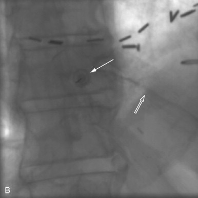
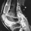
Thoracic spine discography can be performed in the prone or prone semi-oblique 45-degree position (using a wedge) with the less painful side up. The C-arm is rotated to the side of injection until a lucent zone directly in line with the beam is seen projecting over the thoracic disk. The needle should enter the disk lateral to the interpediculate line and medial to the costovertebral joints in order to avoid potential complications such as accidental puncture of the lung or thecal sac. This procedure is often done as a single-needle technique (23 or 22 gauge). The thoracic disk normally accepts a small volume of injectant, less than 1.0 cc. Fluoroscopic images may be difficult to interpret because of the superimposition of osseous structures ( Figure 40-1, B ), difficulty obtaining a true lateral projection, and presence of only a small amount of injected contrast. Therefore, postdiscography CT imaging is often a useful adjunct to delineate internal disk derangement (IDDs) and herniated nucleated pulposus ( Figure 40-2, A ).


Lumbar Spine Technique
The technique for lumbar injection is a posterolateral extradural approach. Levels for injection are chosen based on imaging findings and clinical exam. The most common levels are L3-L4, L4-L5, and L5-S1. The patient is positioned in a prone or a prone-oblique position (with the less painful side up). Each level is set up fluoroscopically so that the disk is parallel to the beam and obliqued so that the superior articular process of the overlying facet joint is slightly posterior to the center of the end plate (30% to 50% zone). The needle is advanced along the x-ray beam toward the disk, past the anterior margin of the superior articular process. A single-needle or coaxial technique is used to place the discography needles in each disk. The coaxial technique may reduce the risk of infection and allows one to redirect the inner needle if needed. The larger outer needle allows rapid positioning at the disk margin, with a small-gauge needle used to penetrate the anular fibers. The L5-S1 disk may be located below the pelvic rim, and can be difficult to access making this coaxial technique helpful. Generally, the x-ray beam is oriented with more caudal angulation than used for the higher levels and is rotated to open a small triangle of access over the iliac crest. Positioning of all needles during placement is checked frequently in the plane along the trajectory of the needle and is supplemented with the anteroposterior and lateral planes as the tip approximates the disk. The tip of the inner needle should be positioned as close as possible to the center of the disk, so that injection is into the nucleus pulposus instead of the innervated annular fibers, which can result in a false-positive pain response. After all needles are placed, typically 1 to 3 cc of contrast (mixed with antibiotic) is injected at each level, with fluoroscopic monitoring and assessment of any pain elicited. A morphologically normal disk demonstrates a central globule of contrast collection or “hamburger bun” configuration and degeneration is indicated by a horizontal, linear distribution of contrast ( Figure 40-1, C ). An anular tear is diagnosed if contrast extends into the periphery of the disk in the expected region of the anular fibers ( Figure 40-2, B ).
EPIDURAL INJECTIONS
Overview and General Considerations
Degenerative disk disease is a common cause of back pain, with or without radicular symptoms. Disk material that extends from its normal position can compress nerve roots, the dorsal root ganglion, or proximal segmental nerve, all of which can cause pain. Disk-based inflammation can also cause pain, which is thought to be due to inflammatory mediators such as phospholipase A2 and others. Disk herniations tend to shrink over time, which can relieve compressive nerve pain, but the injection of corticosteroid can decrease inflammatory mediator-based pain and radiculopathy. Epidural injection is most commonly requested for the lumbar or cervical region.
There is high-quality evidence that lumbar transforaminal epidural corticosteroid injection (ESI) is also useful for lower-extremity radicular pain. However, with regard to axial low-back pain, there is evidence that interlaminar ESI is not useful.
The patient’s pain is estimated with a visual analog scale prior to and following the procedure. The dictated report should include the degree of pain relief and a statement whether relief of the typical pain was complete, partial, or none. This immediate symptomatic improvement is due to the anesthetic component of the injectate (referred to as the “anesthetic phase”). The corticosteroid effect takes several days to initiate and is typically assessed at 1 to 2 weeks postinjection. The duration of effect is variable. For lumbar injections, the patient must be watched, and ambulation should begin with assistance since both motor and sensory block often occur, and the patient may comment on slight difficulty with ambulation.
Following epidural injection, immediate symptomatic improvement is due to the anesthetic component of the injectate. The corticosteroid effect takes several days to initiate and is typically assessed at 1 to 2 weeks postinjection.
Cervical Spine Technique
For cervical nonselective epidural corticosteroid injection, a paramedian interlaminar approach is commonly used. The needle is advanced at the C7-T1 interspace, where capacity of the spinal canal is more generous, and the cord is positioned anteriorly in the thecal sac. Improved efficacy for injection at a higher level has not been proven, even if the likely pain generator is higher, and the risks are increased at higher levels. A paramedian approach allows the physician to determine appropriate needle depth by touching the lamina and then walking off the edge toward the epidural space. This detail should be stressed: The epidural space is much closer to the adjacent lamina in the cervical spine, and therefore placing the needle too deep with dural puncture is more likely. The lateral projection is also used to visualize the needle and prevent passing the spinolaminar line. The injection is similar to the lumbar spine. If the needle appears to be too deep and potentially within the spinal cord substance, then no injection should be performed because this will cause more neurologic damage than just the needlestick itself.
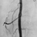
For cervical transforaminal or selective segmental nerve block, the patient is placed supine with the head turned away from the affected side. The C-arm should be positioned so that a good view of the foramen is obtained, and the target zone of the needle tip must be in the posterior inferior corner of that foramen. To determine depth, the C-arm is moved to an anteroposterior position for that level of the spine, accommodating the rotated head position, and the needle should be advanced no more than midway across the articular pillar in this view (50% zone). This zone is identified as the midpoint between a line formed by the uncinate process and the lateral margin of the lateral masses. Using sterile technique after cutaneous local anesthesia, a 25-gauge needle (2.5 or 3.5 in) is directed toward the posterior inferior portion of the target foramen under oblique fluoroscopic control. The vertebral artery runs along the anterior aspect of the foramen just behind (posterolateral to) the uncinate process. In addition, there is a wide array of cervical medullary and segmental arteries in and about the foramen with the least density being in the target zone. Injection of a small amount of contrast should show epiradicular and epidural opacification without vascular uptake ( Figure 40-3, A ). There are several case reports of spinal cord infarction with transforaminal cervical injections; the etiology is felt to be an embolic event from particulate material injected within a cervical medullary artery or branch. In order to minimize this complication, the following technique modifications are suggested: use of digital subtraction angiography during contrast injection to identify spinal artery opacification; if no vascular uptake is identified then perform a test injection of a small bolus of local anesthetic and test the patient for sensory or motor changes; and use of a nonparticulate corticosteroid preparation (dexamethasone).

Thoracic Spine Technique
Thoracic selective injections are performed with the patient in the prone position. The x-ray beam is tilted laterally such that a window is created allowing access between the facet joint, pedicle, transverse process, and rib, similar to the projection for thoracic discography. The beam is tilted craniocaudally such that it is directed “down the barrel” of the pedicle, the lower margin of which is about halfway between the end plates. The area is prepped and draped, the skin entry site is localized fluoroscopically, and subcutaneous short-acting anesthetic is administered. Deeper anesthetic is administered along the angle of the x-ray beam. Next, a 22- to 25-gauge spinal needle is advanced inferior to the pedicle through the aforementioned window until the posterolateral vertebral body is reached or radicular pain is perceived. If there is severe radicular pain, the needle should be repositioned. Care must be taken to avoid the pleural margin more laterally, which is easily visualized fluoroscopically. The needle should not be advanced more medial than the medial margin of the pedicle, which forms the border of the spinal canal.
If there is any blood return from the needle, the tip should immediately be repositioned; in the thoracic spine, especially from T7 to T9, small arterial feeders to the spinal cord can extend through the superior aspect of the neural foramen. Injection of air, short-acting anesthetic, or particulate corticosteroid into these branches has the potential to cause cord infarction. For this reason we also position the needle more inferiorly within the neural foramen, since the feeding vessels run just below the pedicle. Next, contrast injection is performed to verify satisfactory positioning. The injected contrast should extend centrally into the lateral epidural space of the spinal canal and peripherally around the nerve root. If there is vascular opacification, the needle should be repositioned. If the patient complains of acute onset of severe radicular pain immediately upon injection, an intraneural injection may have occurred; injection should be stopped immediately, and the needle should be repositioned. After proper positioning is verified, the anesthetic and corticosteroid mixture is injected with periodic fluoroscopic observation.
Lumbar Spine Technique
The lumbar epidural space can be approached in three ways, caudally: dorsally via an interlaminar or interspinous approach, and via the spinal foramen at a particular level. For the caudal approach, the fact that the thecal sac ends at the S2 level is advantageous because a needle placed through the sacral hiatus is less likely to penetrate the thecal sac than when approached with the other methods. To perform a caudal block, the patient is placed prone on the table, and the low back is prepped and draped in sterile fashion. The sacral hiatus is palpated, identified on anteroposterior and lateral fluoroscopy, and then marked. Care should be made to adequately anesthetize the overlying skin, subcutaneous tissue, and periosteum, as this is a sensitive area for many patients. A 22-gauge spinal needle, straight or curved at the tip, is inserted into the sacral canal, which is confirmed with lateral fluoroscopy to ensure neither dorsal nor ventral needle position. The needle should not be advanced above the S2-S3 disk to minimize risk of dural puncture. Review of MRI is useful to ascertain that dural ectasia with multiple perineural (Tarlov) cysts does not exist. Injection of contrast material is indicated to confirm typical sacral epidurogram, and lack of intravascular uptake ( Figure 40-4 ). A combination of local anesthetic and corticosteroid is injected (usually about a 3-cc volume), followed by 3 to 5 cc of saline. When dural puncture occurs with a caudal approach, a low thecal sac is usually present.


The interlaminar approach is performed with the patient prone. Fluoroscopy is used to visualize the interlaminar space one interspace above or below the most likely pain-generating level. Some physicians inject at the most symptomatic level, but if there is stenosis due to a disk bulge, the injectate can transiently raise intrathecal pressure and be uncomfortable for the patient. The needle is advanced to the inferior margin of the lamina of the vertebra above the target space. The lateral projection is used to confirm that the needle tip is located in the region of the dorsal epidural space. A blunt-tipped needle is preferred by some operators for the procedure. The needle is walked off the lamina into the interlaminar space and slowly advanced into the epidural space. To determine when the epidural space is entered, some physicians advocate continuous light pressure on a glass syringe connected to the needle, detecting loss of resistance. An alternative is to use a low-friction plastic or glass syringe and connecting tube filled almost to the end with contrast. A small quantity of air is left within the tubing when connected to the needle. Slight ballottement on the syringe plunger will cause the meniscus between the air and contrast in the tubing to “bounce” when resistance at the needle tip is present. As the epidural space is entered, the resistance decreases and the meniscus “jumps” forward. The contrast can then be injected to confirm under direct visualization that the needle is within the epidural space. Ideally, the contrast material and injectate should reach the ventral epidural space to theoretically maximize effectiveness. If the dura is punctured, the procedure can be performed at another site and the patient counseled for the risk of headache.
The transforaminal ESI has the intuitive advantage of a more targeted placement of the corticosteroid and anesthetic if injected. The risk of an intradural injection is much lower, but there is an increased possibility of nerve stimulation and pain during the procedure. This can be minimized by careful needle placement. For this technique, the patient is prone so the intervertebral disk of interest is profiled and the image intensifier rotated to access the foramen of the affected level. This is best done by projecting the ring shadow of the pedicle in the upper portion of the vertebral body using an obliquity that allows needle passage lateral to the lamina and under the transverse process. The needle is advanced to a level just under the pedicle at the 6-o’clock position into the “safe triangle.” If the needle comes in proximity to the nerve, the patient can be asked if the sensation follows her or his typical radicular distribution, although the sensation itself will likely be different from their typical pain. Injection of a small amount of contrast can confirm both epidural and epiradicular spread (see Figure 40-3, B ); corticosteroid with anesthetic can then be injected. This is very similar to selective nerve blockade.
Selective segmental nerve blockade (SNRB) is a procedure very similar to transforaminal epidural corticosteroid injection (some use these terms synonymously). SNRB is usually performed as a diagnostic test, but therapeutic injection of corticosteroid is sometimes performed as well. The value of selective nerve blocks is in identifying a particular level as a pain generator. A block that does not relieve the patient’s pain is a strong negative predictor for subsequent surgical benefit. Surgeons might request sequential blocks spaced over time to fully elucidate a patient’s pain generators prior to surgical intervention. That level is targeted with an oblique fluoroscopic approach similar to a transforaminal ESI. With ESI, the “safe triangle” is targeted, compared to SNRB in which the needle is directed slightly lower, just anterior and below the pedicle to approach the postganglionic nerve as it descends and traverses the vertebral body. The goal is to minimally touch the tissue adjacent to the nerve root to elicit a radicular sensation. The patient is asked if that sensation follows their typical pain pattern. If it is a portion of the pattern or all of it, the block is carried out. If the sensation is in a completely different distribution than typical pain, then that level may be blocked with an anticipated negative result or a block one level above or below may be considered.
Targeted epidural corticosteroid injections are most likely to benefit those patients whose imaging studies correlate in a neuroanatomic fashion with their clinical examination findings.
Related posts:

Stay updated, free articles. Join our Telegram channel

Full access? Get Clinical Tree


