Fig. 2.1
Longitudinal waves. The expansion and contraction of piezoelectric crystals caused by the application of alternating current to the crystals causes compression and rarefaction of molecules in the body
The compression and rarefaction of molecules is represented graphically as a sine wave alternating between a positive and negative deflection from the baseline. A wavelength is described as the distance between one peak of the wave and the next peak. One complete path traveled by the wave is called a cycle. One cycle per second is known as 1 Hz (Hertz). The amplitude of a wave is the maximal excursion in the positive or negative direction from the baseline, and the period is the time it takes for one complete cycle of the wave (Fig. 2.2).
Fig. 2.2
Characteristics of a sound wave: the amplitude of the wave is a function of the acoustical power used to generate the mechanical compression wave and the medium through which it is transmitted
The velocity with which a sound wave travels through tissue is a product of its frequency and its wavelength. The velocity of sound in tissues is constant. Therefore, as the frequency of the sound wave changes, the wavelength must also change. The average velocity of sound in human tissues is 1540 m/s. Wavelength and frequency vary in an inverse relationship. Velocity equals frequency times wavelength (Fig. 2.3). As the frequency diminishes from 10 to 1 MHz, the wavelength increases from 0.15 to 1.5 mm. This has important consequences for the choice of transducer depending on the indication for imaging .

Fig. 2.3
Since the velocity of sound in tissue is a constant, the frequency and wavelength of sound must vary inversely
Ultrasound Image Generation
The image produced by an ultrasound machine begins with the transducer. Transducer comes from the Latin transducere, which means to convert. In this case, electrical impulses are converted to mechanical sound waves via the piezoelectric effect .
In ultrasound imaging the transducer has a dual function as a sender and a receiver. Sound waves are transmitted into the body where they are at least partially reflected. The piezoelectric effect occurs when alternating current is applied to a crystal containing dipoles [1]. Areas of charge within a piezoelectric element are distributed in patterns which yield a “net” positive and negative orientation. When alternating charge is applied to the two element faces, a relative contraction or elongation of the charged areas occurs resulting in a mechanical expansion and then a contraction of the element. This results in a mechanical wave which is transmitted to the patient (Fig. 2.4).
Fig. 2.4
Piezoelectric effect . Areas of “net” charge within a crystal expand or contract when current is applied to the surface, creating a mechanical wave. When the returning wave strikes the crystal, an electrical current is generated
Reflected mechanical sound waves are received by the transducer and converted back into electrical energy via the piezoelectric effect. The electrical energy is interpreted within the ultrasound instrument to generate an image which is displayed upon the screen.
For most modes of ultrasound, the transducer emits a limited number of wave cycles (usually two to four) called a pulse. The frequency of the two to four waves within each cycle is usually in the 2.5–14 MHz range. The transducer is then “silent” as it awaits the return of the reflected waves from within the body (Fig. 2.5). The transducer serves as a receiver more than 99 % of the time.
Fig. 2.5
The pulsed-wave ultrasound mode depends on an emitted pulse of 2–4 wave cycles followed by a period of “silence” as the transducer awaits the return of the emitted pulse
Pulses are sent out at regular intervals usually between 1 and 10 kHz which is known as the pulse repetition frequency ( PRF ) . By timing the pulse from transmission to reception, it is possible to calculate the distance from the transducer to the object reflecting the wave. This is known as ultrasound ranging (Fig. 2.6). This sequence is known as pulsed – wave ultrasound .
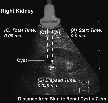
Fig. 2.6
Ultrasound ranging depends on assumptions about the average velocity of ultrasound in human tissue to locate reflectors in the ultrasound field. The elapsed time from pulse transmission to reception of the same pulse by the transducer allows for determining the location of a reflector in the ultrasound field
The amplitude of the returning waves determines the brightness of the pixel assigned to the reflector in an ultrasound image. The greater the amplitude of the returning wave, the brighter the pixel assigned. Thus, an ultrasound unit produces an “image” by first causing a transducer to emit a series of ultrasound waves at specific frequencies and intervals and then interpreting the returning echoes for duration of transit and amplitude. This “image” is rapidly refreshed on a monitor to give the impression of continuous motion. Frame refresh rates are typically 12–30 per second. The sequence of events depicted in Fig. 2.7 is the basis for all “scanned” modes of ultrasound including the familiar gray-scale ultrasound.
Fig. 2.7
Schematic depiction of the sequence of image production by an ultrasound device
Interaction of Ultrasound with Biological Tissue
As ultrasound waves are transmitted through human tissue, they are altered in a variety of ways including loss of energy, change of direction, and change of frequency. An understanding of these interactions is necessary to maximize image quality and correctly interpret the resultant images.
Attenuation refers to a loss of kinetic energy as a sound wave interacts with tissues and fluids within the body [2]. Specific tissues have different potentials for attenuation. For example, water has an attenuation of 0.0 whereas kidney has an attenuation of 1.0 and muscle an attenuation of 3.3. Therefore, sound waves are much more rapidly attenuated as they pass through muscle than as they pass through water (Fig. 2.8). (Attenuation is measured in dB/cm/MHz.)
Fig. 2.8
Attenuation of tissue.) (Adapted from Diagnostic Ultrasound, Third Ed., Vol 1). The attenuation of a tissue is a measure of how the energy of an ultrasound wave is dissipated by that tissue. The higher the attenuation value of a tissue, the more the sound wave is attenuated by passing through that tissue
The three most important mechanisms of attenuation are absorption, reflection, and scattering. Absorption occurs when the mechanical kinetic energy of a sound wave is converted to heat within the tissue. Absorption is dependent on the frequency of the sound wave and the characteristics of the attenuating tissue. Higher frequency waves are more rapidly attenuated by absorption than lower frequency waves.
Since sound waves are progressively attenuated with distance traveled, deep structures in the body (e.g., kidney) are more difficult to image. Compensation for loss of acoustic energy by attenuation can be accomplished by the appropriate use of gain settings (increasing the sensitivity of the transducer to returning sound waves) and selection of a lower frequency.
Refraction occurs when a sound wave encounters an interface between two tissues at any angle other than 90°. When the wave strikes the interface at an angle, a portion of the wave is reflected and a portion transmitted into the adjacent media. The direction of the transmitted wave is altered (refracted). This results in a loss of some information because the wave is not completely reflected back to the transducer, but also causes potential errors in registration of object location because of the refraction (change in direction) of the wave. The optimum angle of insonation to minimize attenuation by refraction is 90° (Fig. 2.9).
Fig. 2.9
A wave which strikes the interface between two tissues of differing impedance is usually partially reflected and partially transmitted with refraction. A portion of the wave is reflected at an angle (θR) equal to the angle of insonation (θi); a portion of the wave is transmitted at a refracted angle (θt) into the second tissue
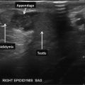
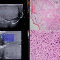
Reflection occurs when sound waves strike an object or an interface between unlike tissues or structures. If the object has a relatively large flat surface, it is called a specular reflector, and sound waves are reflected in a predictable way based on the angle of insonation. If a reflector is small or irregular, it is called a diffuse reflector. Diffuse reflectors produce scattering in a pattern which produces interference with waves from adjacent diffuse reflectors. The resulting pattern is called “speckle” and is characteristic of solid organs such as the testes and liver (Fig. 2.10).
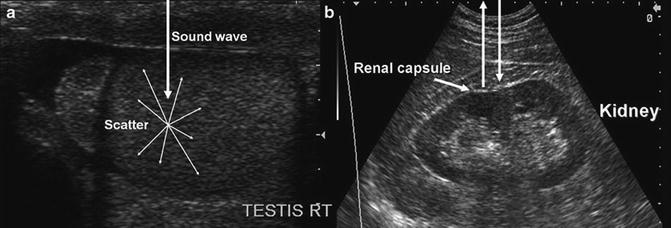
Fig. 2.10
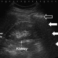
(a) Demonstrates a diffuse reflector. In this image of the testis, small parenchymal structures scatter sound waves. The pattern of interference resulting from this scattering provides the familiar “speckled” pattern of testicular echo architecture. (b) Demonstrates a specular reflector. A specular reflector reflects sound waves at an angle equal to the incident angle without producing a pattern of interference caused by scattering. In this image of the kidney, the capsule of the kidney serves as a specular reflector
When a sound wave travels from one tissue to another, a certain amount of energy is reflected at the interface between the tissues. The percentage of energy reflected is a function of the difference in the impedance of the tissues. Impedance is a property of tissue related to its “stiffness” and the speed at which sound travels through the tissue [3]. If two adjacent tissues have a small difference in tissue impedance, very little energy will be reflected. The impedance difference between kidney (1.63) and liver (1.64) is very small so that if these tissues are immediately adjacent, it may be difficult to distinguish the interface between the two by ultrasound (Table 2.1).
Table 2.1
Impedance of tissue
Tissue | Density (kg/m3) | Impedance (Rayles) |
|---|---|---|
Air and other gases | 1.2 | 0.0004 |
Fat tissue | 952 | 1.38 |
Water and other clear liquids | 1000 | 1.48 |
Kidney (average of soft tissue) | 1060 | 1.63 |
Liver | 1060 | 1.64 |
Muscle | 1080 | 1.70 |
Bone and other calcified objects | 1912 | 7.8 |
Fat has a sufficient impedance difference from both kidney and liver that the borders of the two organs can be distinguished from the intervening fat (Fig. 2.11).
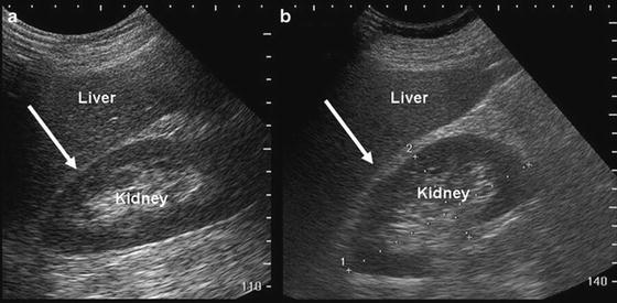
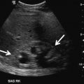
Fig. 2.11
Image (a) demonstrates that when kidney and liver are directly adjacent to each other, it is difficult to appreciate the boundary (arrow) between the capsules of the kidney and liver. Image (b) demonstrates that when fat (which has a significantly lower impedance) is interposed, it is far easier to appreciate the boundary between liver capsule (arrow) and fat
If the impedance differences between tissues are very high, complete reflection of sound waves may occur, resulting in acoustic shadowing (Fig. 2.12).
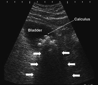
Fig. 2.12
In the urinary bladder, reflection of sound waves as the result of large impedance differences between urine and the bladder calculus (thin arrow). Acoustic shadowing results from nearly complete reflection of sound waves (arrows)
Artifacts
Sound waves are emitted from the transducer with a known amplitude, direction, and frequency. Interactions with tissues in the body result in alterations of these parameters. Returning sound waves are presumed to have undergone alterations according to the expected physical principles such as attenuation with distance and frequency shift based on the velocity and direction of objects they encountered. The timing of the returning echoes is based on the expected velocity of sound in human tissue. When these expectations are not met, it may lead to image representations and measurements which do not reflect actual physical conditions. These misrepresentations are known as “artifacts.” Artifacts, if correctly identified, can be used to aid in diagnosis.
Related posts:

Stay updated, free articles. Join our Telegram channel

Full access? Get Clinical Tree


