- •
The radionuclides of interest for PET emit positrons, the antiparticles of electrons.
- •
Positrons interact with free electrons to produce two back-to-back 511-keV annihilation photons; PET imaging is based on coincidence detection of these photons, not of positrons.
- •
Commercial PET scanners consist of scintillation detectors, in which energy deposited by photon interactions is converted to light; light is converted to electrical signals by PMTs or photodiodes.
- •
Simultaneous detection of a pair of 511-keV photons traveling in opposite directions makes it possible to localize the annihilation event to a line joining the two detectors without the need for the collimators that are used in SPECT.
- •
Scanners with fast scintillation detectors and fast electronics are capable of TOF imaging, which provides additional event localization information based on the difference in detection times of the two photons.
- •
Because it uses electronic rather than physical collimation, PET sensitivity is higher than SPECT sensitivity.
- •
The primary determinants of sensitivity in PET are detector efficiency, which is maximized by using scintillating crystals of high atomic number and high density, and geometric efficiency, which is increased by surrounding the patient with multiple rings of detectors.
- •
Advanced techniques for correction of scatter, randoms, attenuation, and dead time enable quantitative PET imaging.
- •
Emerging technologies include total-body PET and simultaneous PET/MRI systems.
Introduction
In this chapter, we present fundamental principles of positron emission tomography (PET) imaging for clinicians in nuclear cardiology and cardiovascular imaging. We include essential components of the physics, mathematics, and engineering concepts necessary for an understanding of the PET data acquisition and image formation processes. The effects of current and emerging equipment design factors, acquisition choices, and reconstruction algorithm selection on PET image quality, with an emphasis on cardiac PET, are discussed. A more detailed understanding of these topics can be gained by consulting other specialized textbooks. , Other imaging modalities, such as computed tomography (CT) and magnetic resonance imaging (MRI), are covered only in terms of their contribution to PET imaging; readers desiring a more complete treatment are referred to additional specialized readings.
PET physics fundamentals
Positron decay and annihilation
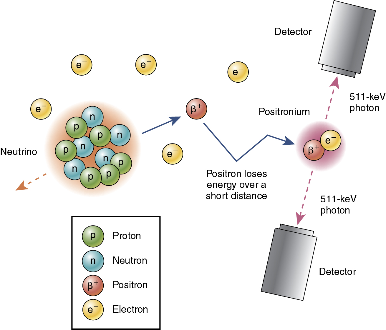
Most naturally existing nuclides are stable (i.e., nonradioactive); unstable nuclides can be created using a cyclotron or accelerator. Unstable nuclides become stable through radioactive decay. Positron emitters, the radionuclides of interest for PET, emit positrons. A positron is the antiparticle of an electron (i.e., the positron and the electron have the same mass and charge), but a positron is positively charged, whereas an electron is negatively charged. The positron is emitted with kinetic energy ranging from zero up to a maximum value, which is characteristic of the radionuclide. The positron travels from the decay site, losing its energy through interactions with bound electrons in tissue, and eventually interacts with a free electron. The electron and positron briefly form an unstable atom called positronium, which exists only for a short time (<0.5 nanoseconds) before annihilating into two photons, each with an energy of 511 keV ( Fig. 2.1 ). The mass of the positron or electron is equivalent to an energy of 511 keV, according to mass-energy equivalence, E = mc 2 , where c is the speed of light ( c = 3 × 10 8 m/sec). The distance between the decay site and the annihilation site (the so-called positron range ) depends on the kinetic energy of the positron and on the tissue composition. The decay-annihilation distance negatively affects the spatial resolution of PET images. PET imaging is based on the detection of 511-keV annihilation photons, not positrons. The two annihilation photons have the same energy of 511 keV, are emitted simultaneously, and travel in opposite directions. These three important physical characteristics of annihilation photons enable efficient detection of coincidence events using an appropriate detection system.
Photon interactions with matter
All 511-keV photons generated from positron decay must travel through the patient’s body before being detected by the PET detector. Therefore it is important to understand how the energetic photon interacts with tissue. The basic attenuating and scattering interactions are described in Chapter 1 . Because the probability of these interactions depends on both photon energy and tissue composition, there are some differences between PET (511-keV photons) and single photon emission computed tomography (SPECT; usually lower energies and, most commonly, 140 keV). In general, the probability of any interaction is lower at 511 keV than at 140 keV, so there is less attenuation (although attenuation is more of a problem in PET. The probability of photoelectric absorption is lower than that of Compton scattering for 511-keV photons in tissue.
The formula for transmission of radiation through matter is given in Chapter 1 . For 511-keV photons, the linear attenuation coefficient is 0.096 cm −1 for soft tissue and 0.172 cm −1 for bone (compared with 0.154 cm −1 and 0.25 cm −1 for 140-keV gamma rays). About 50% of photons are absorbed by an approximately 7.2 cm thickness of soft tissue. Therefore the half-value thickness of soft tissue is 7.2 cm for 511 keV; for bone, it is approximately 4.0 cm. The interaction of 511-keV photons with high-density material, such as scintillation crystals, will be discussed below.
PET imaging technology
PET detectors
PET detection is based on the interaction of the annihilation photons with the detector material. Commercial PET instruments are based on scintillation detectors, described in Chapter 1 , in which energy is deposited by excitation; this is followed by emission of visible or ultraviolet light. The light is converted to electrical signals by photomultiplier tubes (PMTs) or photodiodes (see Chapter 1 ).
Desirable properties of scintillation crystals include: (1) high detection efficiency (attained by using materials with a high atomic number and high physical density); (2) high conversion efficiency, which is the fraction of deposited energy converted into visible or ultraviolet light; (3) short decay times; (4) transparency to emitted light; and (5) an emission spectrum that is well-matched to the sensitivity of the PMT or photodiode. Because of the higher photon energy, a high atomic number and physical density are even more important for PET than for SPECT. Furthermore, fast timing is more important in PET for reasons that will be discussed. Therefore, different scintillators are used in PET ( Table 2.1 ). Commonly used PET detector materials include bismuth germinate (BGO) and lutetium orthosilicate (LSO or LYSO). The advantages of BGO include its high density and atomic number; disadvantages are poor light output, poor energy resolution, and slow decay. High-performance PET systems, such as those with time-of-flight (TOF) capability, use LSO or LYSO. These scintillators have a physical density similar to that of BGO but a somewhat lower atomic number. Importantly, they have high light output, good energy resolution, and fast decay.
| Scintillator | NaI | BGO | LSO | LYSO |
|---|---|---|---|---|
| Density (g/cc) | 3.7 | 7.1 | 7.4 | 7.1 |
| Effective atomic number | 51 | 74 | 66 | 60 |
| Scintillation time (ns) | 230 | 300 | 40 | 41 |
Early PET detectors used individual detector crystals, each coupled to a PMT. Spatial resolution was limited by the size of these units, and the need for a PMT for each detector crystal made decreasing the size of the units prohibitively expensive. Modern PET systems are based on the block detector design ( Fig. 2.2 ), by which the scintillator crystal is segmented into smaller elements by partial cuts through the crystal. Reflective material is introduced into the cuts to render the elements independent. The block is viewed by an array of four PMTs, and interactions are assigned to particular elements by Anger logic.

Photon counting technology
Scintillation crystals are coupled to photodetectors, which convert the light photons emitted by the scintillator to electrons and amplify the signal (see Chapter 1 ). Desirable properties of photodetectors include: (1) high gain (amplification of electric signal), (2) high quantum efficiency (fraction of incident light photons converted to electrons), (3) fast timing (required for TOF PET), (4) compact size (for good spatial resolution), (5) low operating voltage, (6) room-temperature operation, and (7) insensitivity to magnetic fields (required for PET/MRI). There are three types of photodetectors used in nuclear medicine ( Table 2.2 ): PMT and two types of photodiodes, avalanche photodiodes (APDs) and silicon photomultipliers (SiPMs; see Chapter 1 ). PMTs, based on mature vacuum-tube technology, were until recently the most commonly used. A major disadvantage of PMTs for PET is that they are bulky; PET systems use small detectors, unlike SPECT systems, which most commonly use large crystals. APDs have been used in some PET applications, but widespread adoption is unlikely because of relatively low gain and slow timing. SiPMs are more promising; like APDs, they are compact and insensitive to magnetic fields. Unlike APDs, they are fast, with high sensitivity and good resolution, and they operate at low voltage. These devices are used in advanced or newer PET systems.
| PMT | APD | SiPM | |
|---|---|---|---|
| Quantum efficiency | 25% | 80% | 50%–80% |
| Gain | 10 6 –10 7 | 10 2 –10 3 | >10 7 |
| Size | Bulky | Compact | Compact |
| Timing | Fast | Slow | Very fast |
| Operating voltage | High | High | Low |
| Cooling required | No | Yes | No |
| Sensitive to magnetic fields | Yes | No | No |
PET data acquisition
Types of coincidence events
The two annihilation photons are assumed to have the same energy of 511 keV, to be emitted simultaneously, and to travel in opposite directions. These physical characteristics make it possible to limit the volume within which the event might have taken place without a collimator, which is used for this purpose in SPECT. High-density scintillation detectors are required to detect the 511-keV high-energy photons (see Fig. 2.1 ). Coincidence timing is used to determine whether two detected photons originated from the same event. The detection time for each photon is recorded; if the time difference is less than a defined timing window, then it is assumed that the photons are from the same annihilation (see Fig. 2.1 ). The coincidence timing window depends on the temporal properties of the scintillation crystal, the photodetection system, and other electronic components. A 511-keV photon travels about 30 cm in 1 nanosecond. For a 70-cm diameter PET ring, the maximum time difference between two annihilation photon detections is 2.3 nanoseconds. Therefore the timing window must be greater than 2.3 nanoseconds. Typical timing windows are 6 to 12 nanoseconds for non-TOF system and 3 to 6 nanoseconds for TOF systems. Detector blocks are arranged in a circular geometry to efficiently detect pairs of annihilation photons traveling in opposite directions; many more coincidence detections from a given radioactive location are possible using the circular detector arrangement shown in Fig. 2.3 .

A line connecting the two locations where the annihilation photons were detected is called a line of response (LOR). It is assumed that the annihilation occurred somewhere along the line. Pairs of events detected within the coincidence timing window are called prompt coincidences (P). True coincidences (T) are those for which both photons originated from the same positron-electron annihilation and neither underwent an interaction before being detected ( Fig. 2.4 A). If one or both photons are scattered within the patient body before detection within the coincidence window (scattered coincidences [S]), the result is spurious location information (see Fig. 2.4 B) and degraded image quality. Scattered photons must be removed or accounted for in quantitative PET imaging. The energy of Compton-scattered photons is less than the original 511 keV (see Chapter 1 ); therefore, increasing the lower limit of the energy window will reduce (but not eliminate) the detection of scattered photons. A typical energy window is between 425 and 650 keV.

It is possible for photons from two different annihilation events to be detected within the timing window. In Fig. 2.4 C, one photon from each of the events shown in red and orange escaped, and the two unrelated photons were detected within the coincidence timing window, giving rise to a spurious LOR. These events are called random coincidences (R). Unlike S and T coincidences, which arise from radioactivity within the scanner field of view, R coincidences can include photons from radioactivity outside the field. Therefore estimating R coincidences is complicated. Methods to correct for scatter and randoms will be discussed below.
Noise and noise-equivalent count rate
The quality of nuclear medicine images is often assessed in terms of signal-to-noise ratio (SNR), where the signal is determined by the detected counts that are used in the image and the noise level is determined by uncertainty in the measurement of the signal. Radioactive decay and detection of radiation are random processes, and count measurements follow the Poisson distribution, in which the standard deviation is the square root of the signal; therefore <SPAN role=presentation tabIndex=0 id=MathJax-Element-1-Frame class=MathJax style="POSITION: relative" data-mathml='SNR∼N/N=N’>SNR∼?/?‾‾√=?‾‾√SNR∼N/N=N
SNR ∼ N / N = N
, where N is the detected counts. In PET imaging, image formation is based on the detection of three types of coincidences, T—S—R, and on reconstruction of tomographic images with correction for attenuation, randoms, scatter, and dead time. Therefore the relationship between detected counts and PET image SNR is complex. It has been shown that the SNR in PET images of a uniform object (e.g., a cylinder filled with fluorodeoxyglucose) is related to the scanner’s noise-equivalent count rate (NECR); therefore, NECR is used in the performance evaluation of PET scanners and in estimating image quality based on count rate. The NECR is defined as
NECR=T2T+S+kR.
Related posts:
Stay updated, free articles. Join our Telegram channel

Full access? Get Clinical Tree


