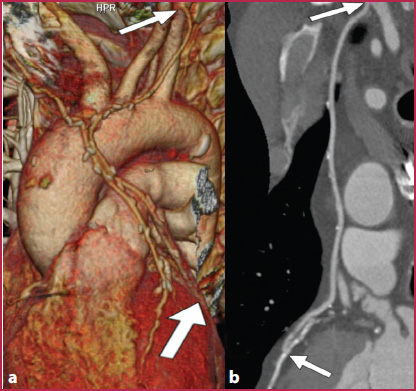
Fig. 3.1
CT angiography of the thoracoabdominal aorta. Axes rearranged perpendicularly to the vessel course. a The 3D Volume Rendering reconstruction allows visualization of the scoliotic course of the aorta at the diaphragmatic hiatus (arrow). b Direct axial reconstruction arbitrarily oriented perpendicular to the CT bed allows for an accurate measurement of the aortic diameter at mid-chest (line A and c), but are oblique to the long axis of the vessel in proximity to the diaphragm (line B and d), resulting in an imprecise measurement. e To obtain an accurate measurement of the aorta’s maximum diameter at the diaphragmatic hiatus, reconstruction must be rearranged orthogonally to the long axis of the vessel (dashed line and f)
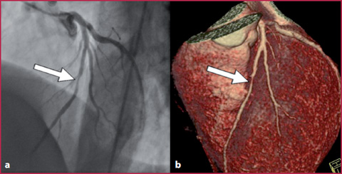
Fig. 3.2
Left coronary system, arterial stenosis. Comparison between coronary angiography (a) and 3D VR reconstruction (b), severe non-calcified stenosis of the middle part of the anterior descending artery
Moreover, post-processing techniques have made understanding and interpreting CT and MRI easier for non-radiologists (Fig. 3.2).
The advanced post-processing techniques (Multiplanar Reconstruction, MPR; Curved Planar Reformation, CPR; Maximum Intensity Projection, MIP; Minimum Intensity Projection, MinIP and Volume Rendering, VR) are the topic of this chapter. However, the importance of the planar reconstructions should not be underestimated, especially in MRA and even more for CTA, because it is the essential basis to generate volumetric data to obtain high quality 3D reconstructions.
3.1 3.1 Planar Reconstructions
The main parameters which must be taken into consideration when performing planar reconstructions are described below.
Reconstruction filters (CTA): the use of sharp reconstruction filters, which may lead to a better definition of vascular contours in planar images, introduce a reduction in the Signal-to-Noise Ratio (SNR), which can interfere with the three-dimensional reconstruction. Regarding this issue, datasets reconstructed using smooth filters are preferable, mostly when volume rendering reconstructions are required.
Window level and width (CTA): the vessel lumen should not be visualized with the highest values of the gray scale (white). If this happens, the gray scale is interrupted and, therefore, it is possible that the size of the vessel could be misrepresented or wall calcifications, metallic stents, and other devices may be confused with the vessel lumen, which is opacified by the contrast medium. Hence, calcifications and metal devices may appear indistinguishable from the vessel lumen, leading to misinterpreted diagnoses such as underestimation of luminal stenosis.
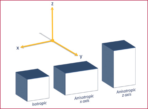
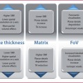
Reconstruction (CTA) and acquisition (MRA) geometry: planar field of view (FoV), matrix size, slice thickness and reconstruction intervals are the key parameters that determine the voxel size. For high-quality reconstructions, the three axial dimensions of each voxel should be as similar as possible (isotropy) (Fig. 3.3). Voxel anisotropy could lead to artifacts in all types of reconstructions, such as the stair–step artifacts, which are image distortions caused by a dimensional excess of the z axis (excessive slice thickness).
Fig. 3.3
Schematic representation of the voxel geometry. A voxel is isotropic when it is characterized by identical dimensions along the three Cartesian axes (x, y, z). When one of the dimensions of the voxel is higher, the voxel is anisotropic (planar anisotropy or along the z axis)
3.2 3.2 Advanced Post-Processing Techniques
MPR
The MPR technique is a 2D approach that enables the operator to select the imaging reconstruction plan. If the direct reconstruction plan is axial, MPR images can be arbitrarily reconstructed in several planes, such as the sagittal or coronal plane, or with various degrees of obliquity. The main advantages of the MPR technique are the speed of execution and its availability on most reporting workstations.
However, since vessels are curved structures (rarely perpendicular, lateral or frontal with respect to the scanner bed), it is necessary to properly orient the reconstruction axes based on the examined structure. The primary limitation of MPR techniques regarding cardiovascular examinations is their 2D approach: the scroll functions must be used to fully explore the whole vessel and it is not possible to present all the information concerning the examined volume in a single image.
Moreover, it should also be noted that in the MPR images the information from extra-vascular voxels (bone and parenchyma) is not removed and, therefore, it is not possible to perform a pure angiographic assessment. On the other hand, this allows for an examination of the abnormalities in others organs such as the kidney, liver, spleen, heart and lungs.
CPR
Reconstructions of 2D planar curves can compensate for the limitations of MPR techniques in the evaluation of tortuous vascular structures: these reconstructions are performed by tracing curved lines with progressive reference points through the images during scrolling (planar or MPR); subsequently, the curved structures are represented on a single plane.
This is the best 2D technique to visualize vascular structures and is crucial for the interpretation of several vascular diseases such as thrombosis, dissections, intimal flaps or during the evaluation of high-density endoluminal material, such as wall calcifications or metallic endovascular devices (Figs. 3.4–3.5).
The CPR is also the most accurate method for the quantification of luminal stenosis and is considered the standard reference for this task in several diagnostic centers.
Until a few years ago, CPR reconstructions were only performed manually (by tracing a point-by-point segmentation through the curved trajectory of the vessel), which resulted in an increased execution time. More recently, many software programs that allow for the automatic creation of CPR by selecting the start and end points only have been developed, helping operators to reduce reconstruction time. These software, however, have some limitations: the correct vascular axis is not always identified and the trajectory automatically calibrated by the software may fall outside the lumen or produce loop artifacts near large vessels. To reduce errors, an operator needs to check the automated process (Fig. 3.6).
Get Clinical Tree app for offline access
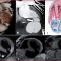
Fig. 3.4
Curved planar reformation. a 3D VR frontal plane reconstruction from a CTA examination performed during follow-up after coronary artery bypass grafting using both internal mammary arteries. b


Related posts:
Stay updated, free articles. Join our Telegram channel
Full access? Get Clinical Tree
