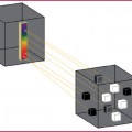
Fig. 1.1
Single-slice spiral scanning (a) in which a single slice for each tube rotation is acquired. Spiral volumetric scanning (b): increasing the detectors number it is possible to cover a larger area for each rotation along the z axis
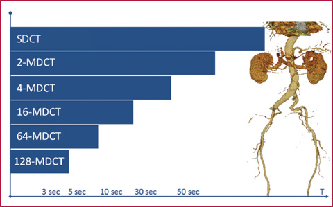
Fig. 1.2
Increasing the number of detectors decreases the acquisition time for a volume of the same amplitude: the acquisition time for the study of the aorta is reduced to an adequate scan time using a minimum of 4 slice detectors
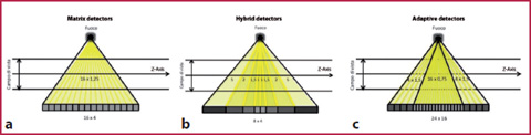
Fig. 1.3
Different multi-detector CT systems: a matrix detectors; b hybrid detectors; c adaptive detectors
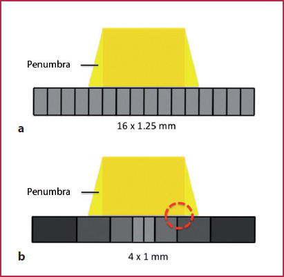
Fig. 1.4
a The geometrical effectiveness of a system depends on the so-called penumbra effect (the amount of diffuse radiation) compared with the total radiation reaching the detector surface area. b Reducing the number of interfaces in the peripheral regions of the detector panel increases the number of registered photons (even those with an oblique inclination) with the result of augmenting detector efficiency and thus the effectiveness of the geometric dose
Scan Parameters
The study of vascular structures, and in particular those of small dimensions (for example the coronary vessels), requires high spatial resolution, with particular regard to the selection of an adequate thickness layer. At the same time it is also essential to respect the technical conditions that represent the optimal compromise between spatial and temporal resolution and image quality (Signal to Noise Ratio / SNR): with the use of old-generation scanners (16 multi–detector Computed Tomography (MDCT)) it is not possible to perform high-resolution CTA examinations (<1.5 to 3 mm) in short times and with large acquisition volumes, whereas with the use of new-generation equipment (64-128-320 MDCT), although it is possible to acquire submillimetric layers in any anatomical region, it is necessary to take into account the fact that the increase in spatial resolution leads to a reduction of SNR. When setting-up the CTA protocols, it is essential to know how to handle a number of additional parameters, during both image acquisition and reconstruction.
Acquisition Parameters
Detector collimation: varies the amplitude of the photon beam used to detect the attenuation profiles of the object under examination. It is determined by the opening degree and by the number of the detectors used in the selected configuration.
Pitch: ratio between the table feed speed and the gantry rotation speed, multiplied by the collimation of the beam:
(TF = Table Feed per rotation; N = number of detectors; C = beam collimation).
Current intensity and the potential difference at the X–ray source: the conductor current intensity (milliamperes / second, mAs) of the X-ray tube determines the number of photons produced by the tube itself, whereas the potential difference (kilovolts peak, kVp) determines their power. By increasing the mAs we can obtain images with a better contrast resolution and with a lower noise; increasing the kVp instead will obtain better penetration of the photon beam (Figs. 1.5, 1.6). The dose administered increases linearly for mAs and with an exponential relationship as regards the kVp.
Reconstruction Parameters
Slice thickness: effective thickness (expressed in mm) of the contiguous slices obtained in the transverse reconstruction plane. It can be equal to or greater than the value of the collimation, but not less than it. The layers can be reconstructed with a thickness greater than the collimation in order to obtain a dataset consisting of a smaller number of images and with a lower noise (Fig.1.7).
Reconstruction Interval (RI): represents the degree of overlap, expressed in millimeters, of two contiguous slices. It can be set to values higher, equal or less than the slice thickness, resulting, respectively, in layers which are spaced, adjacent or overlapped. Reconstructing slices with relatively high thickness (for example 3 mm), but with reduced IR (1–1.5 mm), may make it possible to obtain an adequate spatial resolution along the z axis even with less efficient equipment.
Field of View (FoV): this represents the sizes (expressed in millimeters) of the planar images on the transverse plane. The FoV size must be selected according to the compromise existing between the spatial resolution and the image noise: small FoVs, which are necessary for the assessment of structures with limited dimensions, results in a SNR reduction (Fig.1.8).
Reconstruction matrix: indicates the number of pixels in each image. It is normally fixed (512 x 512), but may be varied in dynamic studies (for example for the evaluation of cardio-CT kinetics) in order to reduce the size of the stored data.
Reconstruction algorithms (or convolution filters): they are used to reconstruct images from the raw data. Information on the attenuation profiles of the object under examination are reworked by means of mathematical algorithms that apply appropriate correction functions to the data before the production of the final image. This leads to the highest influence on the quality of the planar reconstructed image (Fig.1.9).
In all CT scanners various types of filter are available to vary the degree of definition of the image profiles (filters for bone, soft tissue, etc.). The choice of the more appropriate filter is finalized to modify an intrinsic characteristic of the scanned image (for example, the planar spatial resolution for studies of the lung parenchyma), reducing or emphasizing the effect in the reconstruction phase. The use of high-definition filters (sharp) increases spatial resolution, but also the image noise; the use of soft filters (smooth) reduces the definition, but also the noise level.
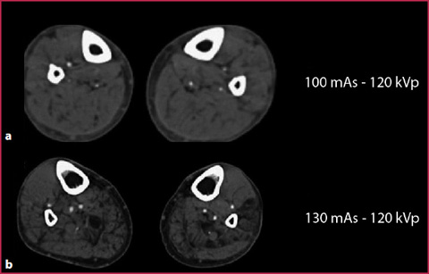
Fig. 1.5
CTA of the peripheral arteries in two patients with a similar body mass, evaluated both at 120 kVp but with 100mAs (a) and 130 mAs (b), respectively. The use of a higher mAs value produces an image with less noise and a greater contrast resolution
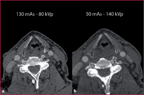
Fig. 1.6
Exam performed with the Dual-Energy technique on a dual source scan, using the same patient and variable values of kVp and mAs. By reducing the value of the kVp (a) it is possible to obtain an image with a contrast resolution comparable to that present in an image obtained using a much higher kilovoltage (b). However, despite the increase in the mAs value on the low kVp scanning (a), the parameter with the greatest effect on the SNR is represented by the effective photon power and not by their number (higher noise in the image obtained at high mAs and low kVp values)
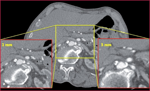
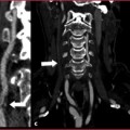
Fig. 1.7
Detail of the abdominal vessels in an image reconstructed with a slice thickness of 1 mm (a) and 3 mm (b): the greater spatial resolution increases the visibility of fine details but reduces the SNR
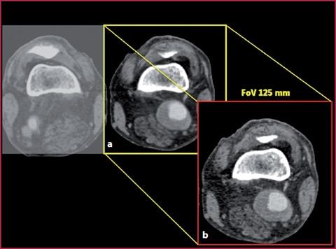
Fig. 1.8
Study of the peripheral extremity vessels obtained for both legs with a 350 mm FoV (a); detail of the limb affected by disease with 125mm FoV (b): also in this case the greater spatial resolution leads to a reduction in the SNR
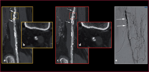
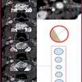
Fig. 1.9
Details of the femoral vessels in a patient with steno-obstructive disease (arrows). The use of a sharp filter (c, d) allows better delineation of the vessel wall profiles and a more adequate identification of the lumen/plaque interface compared with the use of a softer filter (a, b). The conventional angiography examination confirms the presence of multiple steno-obstructive vascular alterations (arrows)
Signal-to-Noise Ratio
All variations of the parameters described, during both the acquisition and reconstruction phase, help to determine the image quality, measured quantitatively with SNR, which is defined as a numerical size which correlates the power of the useful signal with the noise in any system of acquisition, processing or transmission of the information:
![$$ \begin{array}{c} SNR= signal\Big/ noise \\ \begin{array}{ccc} \mathrm{where} & 0<\mathrm{SNR}> & \yen \end{array} \end{array} $$” src=”/wp-content/uploads/2016/03/A978-88-470-2868-5_1_Chapter_TeX2GIF_Equb.gif”></DIV></DIV></DIV>.</DIV><br />
<DIV class=Para>The noise in CT is generally divided into <SPAN class=EmphasisTypeItalic>quantum noise</SPAN> and <SPAN class=EmphasisTypeItalic>electronic noise</SPAN>. The quantum noise is the expression of the probabilistic nature of the interaction between the ionizing radiation and the tissues, whereas the electronic noise is due to the mathematical approximation of the procedures that govern the image reconstruction. In general, the noise presence is related to random and systematic errors due the choice of the image acquisition parameters or also by intrinsic patient factors, such as body mass. The parameters described and their effects on the image are illustrated in <SPAN class=InternalRef><A href=]() Figures 1.10 and 1.11.
Figures 1.10 and 1.11.
Get Clinical Tree app for offline access

1.2 1.2 Contrast Medium Administration
Iodinated contrast agents used in CT are iodine-based substances (with a high atomic number), capable to determine X-ray attenuation. Therefore, for the same administration parameters (total dose of contrast medium and infusion speed expressed in ml / sec) and scanning parameters (mAs and kVp), the higher the iodine concentration (expressed in mgI / ml), the greater the enhancement obtained.
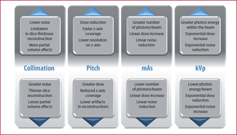
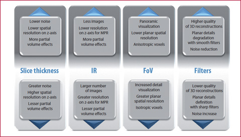
Fig. 1.10
The chart shows the effects induced by changes in different acquisition parameters
Fig. 1.11
The chart shows the effects induced by changes in different reconstruction parameters
The iodinated contrast agents currently available on the market are distinguished by chemical-physical characteristics and iodine concentration, and are water-soluble molecules whose toxicity is significantly lower than that of the older ionic types. These contrast agents are molecules with an interstitial type of biodistribution, whose pharmacokinetics are summarized in Figure 2.13. Once administered intravenously, they undergo an initial phase of vascular distribution, followed by an interstitial phase.
Contraindications to the Use of Contrast Medium
Contraindications to the use of iodinated contrast agents include:
History of previous allergic events related to contrast media or atopy (rhinitis, urticaria, food allergy, allergic asthma). In these cases appropriate prophylaxis must be applied (ESUR guidelines: prednisolone 30 mg – 12 h and 2 h before the examination).Related posts:

Stay updated, free articles. Join our Telegram channel

Full access? Get Clinical Tree