Common trunk
Left anterior descending artery (Anterior interventricular artery) Circumflex artery Intermediate branch
Diagonal branches Septal branches Obtuse marginal branches
Right coronary artery
Sinus node artery
Conal artery
Acute marginal branches
Posterior descending artery (Posterior interventricular artery)
Right or left origin in relation to the cardiac dominance
Postero-lateral branch
Table 9.2
Left coronary artery
1. Common trunk |
2. Left anterior descending artery |
3. Circumflex artery |
4. Intermediate branch |
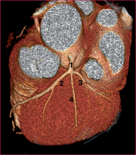
Fig. 9.1
1, Common trunk. 2, LAD. 3, Cx. 4, Intermediate branch
In case of right coronary artery dominance (about 80-90% of cases) the Cx artery is generally thin and may end midway. Conversely, in cases of left dominance, the RCA will not be visible in the distal tract.
The RCA (Fig. 9.5) originates from the right sinus of Valsalva: after branching off into the sinus node branch, its course enters the ipsilateral atrioventricular sulcus, circling the right margin of the heart until it reaches the diaphragmatic surface. Along its course it also gives rise to acute marginal branches, that divide the artery into three parts:
proximal tract (from the origin to the first marginal branch);
middle tract (from the first to the second marginal branch);
distal tract (from the second diagonal branch to the end of the vessel).
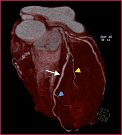
Fig. 9.2
Left anterior descending artery. White arrow: LAD. Yellow arrowhead: first diagonal branch. Blue arrowhead: second diagonal branch
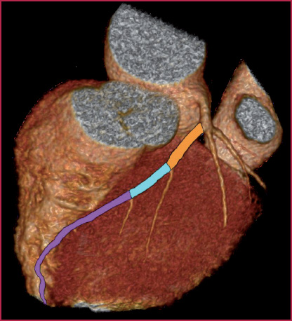
Fig. 9.3
Left anterior descending artery. Orange: proximal tract. Blue: middle tract. Purple: distal tract
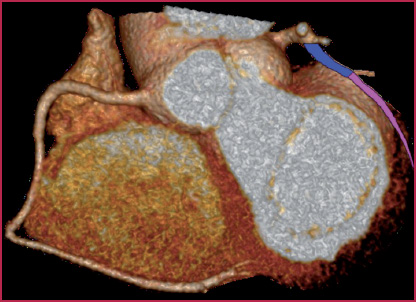
Fig. 9.4
Circumflex artery. Blue: proximal tract. Purple: distal tract
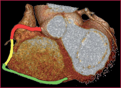
Fig. 9.5
Right coronary artery. Red: proximal tract. Yellow: middle tract. Green: distal tract
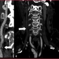
The posterior descending artery (PDA) and the postero-lateral branch run (Fig. 9.6) respectively in the interventricular posterior and atrio-ventricular sulci, supplying part of the diaphragmatic surface of the heart.
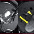
Coronary dominance (Fig. 9.7, Table 9.3) is determined by the origin of the posterior descending artery and of the postero-lateral branch. The importance of the concept of coronary dominance lies in the fact that the dominant vessel supplies the inferior wall of the left ventricle; so for example, the occlusion of a Cx dominant would lead to a very extensive myocardial infarction involving the lateral wall (normal irrigation territory) and the inferior wall (irrigated by the posterior interventricular branch).
Right dominance: the PDA and the postero-lateral branch originate from the right coronary artery.
Left dominance: the PDA and the postero-lateral branch originate from the left coronary (generally from Cx).
Co–dominance: the PDA originates from the right coronary artery, whereas the postero-lateral branch originates from the Cx.
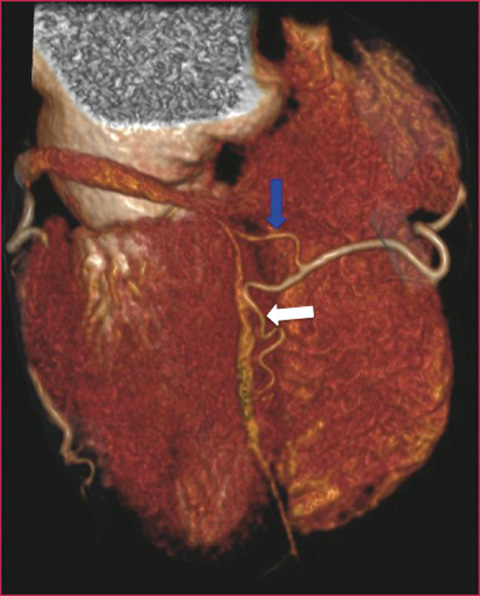
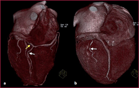
Fig. 9.6
Coronary CTA, volume rendering image, posterior view. Posterior descending artery. Blue arrow: posterolateral branch. White arrow: posterior interventricular artery
Fig. 9.7
a Right dominance: the posterolateral branch (yellow arrow) and the posterior interventricular branch (white arrow) originating from the right coronary artery. b Left dominance: the posterior interventricular branch (arrow) originating from the circumflex artery
Table 9.3
Coronary dominance
RIGHT | 90% |
LEFT | 7-8% |
CO-DOMINANCE | 2-3% |
Anomalies of Origin and Course
Anomalies of origin (Figs. 9.8-9.9) are divided into two categories: minor (benign) and major (malignant).
Minor anomalies of origin (benign): also known as non–interarterial because the abnormal vessel does not run, by definition, between the pulmonary trunk and ascending aorta, and is therefore not imprinted from the outside, especially during increased cardiac inotropism and chronotropism (for example during physical activity); such anomalies usually present no significant problems from a clinical and prognostic point of view.
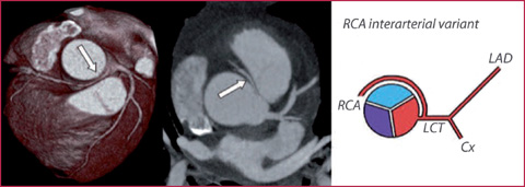
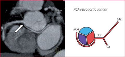
Fig. 9.8
Abnormal origin of the RCA (arrow) from the left sinus of Valsalva, malignant interarterial variant. Cx, circumflex artery, LAD, left anterior descending artery, LCT, left common trunk
Fig. 9.9
Abnormal origin of the RCA (arrow) originating from the left sinus of Valsalva with retroaortic course (benign variant)
Major anomalies of origin (malignant): are the interarterial variants (with the course of the vessel between the pulmonary trunk and ascending aorta), possibly having relevant clinical consequences (angina, syncope, acute myocardial infarction as well as sudden death). In these cases, the symptomatology is correlated with compression of the coronary artery from the arterial trunks during the systolic phase.
Intramyocardial Bridging
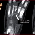
Among the anomalies of course, the intramyocardial bridging is the intramural course of a coronary artery (typically the LAD) (Fig. 9.10).
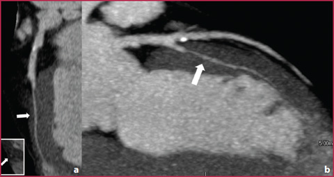
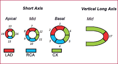
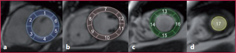
Fig. 9.10
a Intramyocardial course (bridging) of the LAD. b Curved Planar Reformation analysis of the LAD with multiplanar reconstructions; the intramyocardial artery tract is indicated by the arrow
Fig. 9.11
Coronary blood supply territories
Fig. 9.12
Cardiac MR 17-segment left ventricular segmentation. a Basal plane: 1 anterior, 2 antero-septal, 3 infero-septal, 4 inferior, 5 infero-lateral, 6 antero-lateral. b Mid plane: 7 anterior, 8 antero-septal, 9 infero-septal, 10 inferior, 11 infero-lateral, 12 antero-lateral. c Apical planes: 13 anterior, 14 septal, 15 inferior, 16 lateral. d Apex: 17 apex (modified from the American Heart Association model)
The symptomatology, not always present, is due to dynamic stenosis of the vascular lumen from the myocardial wall during the systolic contraction, manifested by occasional episodes of myocardial ischemia during stress.
Coronary Segmentation and Myocardial Blood Supply Territories
Concerning the anatomy of the myocardium, in Fig. 9.11 the left ventricular myocardial blood supply is shown; in Fig. 9.12 left ventricular segmentation is seen.
9.2 9.2 CTA Technique
Patient Preparation
The patient’s heart rate must be less than 70 beats per minute (spontaneous or induced by the administration of beta blockers). An example of the administration regimen for beta blockers such as propranolol:
orally: 40 mg of the beta blocker drug 60–90 minutes prior to multislice computed tomography or, starting from 3 days before, 20 mg/day;
intravenous administration: vial of 5 mg of the beta blocker diluted with 20 mL of a saline flush, administered in 4 progressive doses before the examination, monitoring the patient’s blood pressure and pulse;
Possible administration of sublingual nitrates to facilitate coronary dilatation;
Obtain proper breathing during the scan (to avoid artifacts related to respiratory motion);
Put the patient in the supine position with the arms raised;
Perform cardiac synchronization (positioning the electrodes correctly): it is essential to obtain an easily recognizable QRS complex with a sufficiently high R wave voltage.
Image Acquisition
The ECG is characterized by a QRS complex that corresponds to the ventricular systole, preceded by a P wave (atrial systole) which is followed by a T wave (ventricular repolarization). The fundamental concept in coronary CT (Fig. 9.13) is to acquire images in a phase of relative immobility of the heart and of the coronary arteries, which corresponds (especially with scanners that do not belong to the latest generation, with relatively low temporal resolution) to the ventricular meso-telediastole, i.e. the P wave.
The duration of the diastolic phase progressively shortens with the increase in heart rate.
Acquisition protocols are divided in two groups: ECG prospective gating (selection of the signal) and retrospective gating.
Prospective Gating
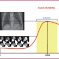
Prospective gating is the acquisition of images in a single phase of the cardiac cycle (usually always during diastole) (Fig. 9.14, Table 9.4), using a sequential technique.
The advantages of this technique are as follows:
quantification of the coronary calcium;
reduction of the effective dose by about 50%.
The disadvantages, however, are:
image acquisition in a single phase of the cardiac cycle, with the risk of artifacts in the event of cycle variability;
no functional imaging.
Retrospective Gating
Retrospective gating refers to image acquisition throughout the entire cardiac cycle (R-R interval) (Table 9.5, Fig. 9.15).
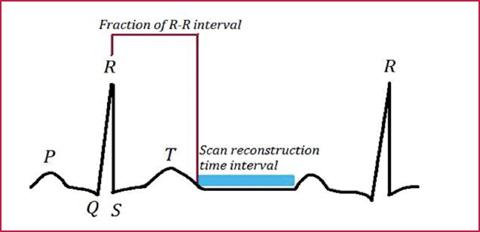
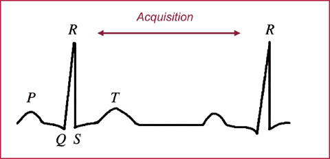
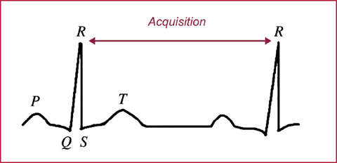
Fig. 9.13
The examination is performed by synchronizing the CT scans with the patient’s electrocardiogram
Fig. 9.14
Prospective gating
Table 9.4
Prospective gating
Advantages | Disadvantages |
|---|---|
Quantification of coronary calcium | Information relative to a single phase of the cardiac cycle |
Low radiation dose | Sequential acquisition |
Reduction in duration of respiratory apnea | |
Stationary table during acquisition |
Fig. 9.15
Retrospective gating
Table 9.5
Retrospective gating
Advantages | Disadvantages |
|---|---|
Possibility of reconstruction in all phases of the cardiac cycle | Higher radiation dose |
Less affected by variations in heart rate | |
Cardiac function evaluation | |
Helical acquisition |
Table 9.6
Use of contrast medium in coronary CT
Contrast | 4 MDCT | 16 MDCT | 64 MDCT | 128 MDCT | Dual source |
|---|---|---|---|---|---|
Contrast medium concentration (mg1/mL) | 350-400 | 350-400 | 350-400 | 350-400 | 350-400 |
Contrast medium volume (mL) | 90-75 | 65-55 80–90 (for by-pass study) | 60-50 80–90 (for by-pass study) | 60-50 80–90 (for by-pass study) | 60-50 80–90 (for by-pass study) |
Saline flush volume (mL) | 50-80 | 50-80 | 40 | 40 | 40 |
Flow rate (mL/s) | 4.0 | 4.0 | 4.0-5.0 | 4.0-5.0 | 4.0-5.0 |
Table 9.7
Coronary CT: technical parameters
4 MDCT | 16 MDCT | 64 MDCT | 128 MDCT | |
|---|---|---|---|---|
KVp | 120 | 120 | 120 | 120 |
mAs | From 200 to 300 | From 200 to 300 | From 180 to 200 (Dose Modulation) | 180 (Dose Modulation) |
Collimation | 4 × 1–2.5 | 16 × 0.4-0.75 | 64 × 0.4-0.625 | 128 × 0.6 |
Slice thickness (mm) | 1-3 | 0.625-1 | 0.5-1 | 0.6 |
Recon increment (mm) | 0.4-0.6 | 0.5-1 | 0.5 | 0.4 |
The advantages of this technique are:
possibility of reconstruction in all phases of the cardiac cycle;
less influence of heart rate variability;
possibility to evaluate cardiac function;
helical acquisition.
As for the disadvantages:
the radiation dose is potentially high.
Key factors in the evaluation of coronary circulation are as follows:
high flow injection rate (> 4 mL/s);
high iodine concentrated contrast medium (CM);
scan times as short as possible, while maintaining pitch range within the limits. In Tables 9.6 and 9.7 the relative reference parameters of different generations of tomographs can be seen.
Data Reconstruction
Related posts:
Stay updated, free articles. Join our Telegram channel

Full access? Get Clinical Tree


