1
Aortic arch
2
Innominate artery
3
Subclavian artery
4
Common carotid artery
5
Internal carotid artery
6
External carotid artery
7
Vertebral artery
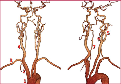
Fig. 6.1
Carotid arteries
Table 6.2
Internal carotid artery
Segments | Course |
|---|---|
Cervical segment (red) | – |
Petrous segment (carotid canal) (yellow) | Caroticotympanic (c) Artery of the pterygoid canal (c) |
Cavernous segment (green) | Cavernous, semilunar, hypophyseal branches, anterior meningeal branch |
Cerebral segment (blue) | Ophtalmic artery (c) Anterior choroidal artery (t) Anterior cerebral artery (t) Middle cerebral artery (t) Posterior communicating artery (t) |
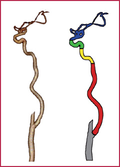
Fig. 6.2
Internal carotid artery
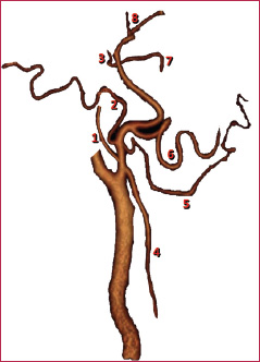
Fig. 6.3
External carotid artery
Table 6.3
External carotid artery
Branches | Course |
|---|---|
Posterior collateral branches | 1. Ascending pharyngeal artery 2. Occipital artery 3. Posterior auricular artery |
Anterior collateral branches | 4. Superior thyroid artery 5. Lingual artery 6. External maxillary artery (Facial artery) |
Terminal branches | 7. Internal maxillary artery 8. Superficial temporal artery |
Frequently, atherosclerotic disease is responsible for changes in the course of the vessel that lead to progressive malacia of the arterial walls, with consequent stretching and straining of the vessel.
Although the described anomalies mostly involve the carotid arteries, they can also affect vertebral or, occasionally, subclavian arteries.
Sometimes a pronounced kinking can cause significant blood flow acceleration, resulting in consequences similar to those for lumen stenosis.
The main morphological and course-related anomalies are mentioned in Figs. 6.4 and 6.5, respectively.
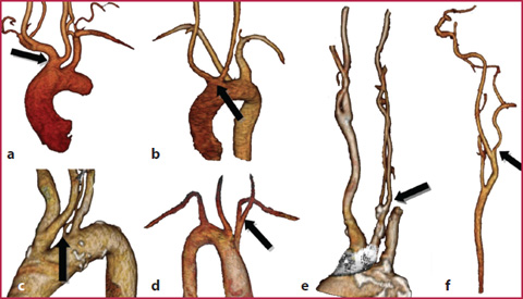
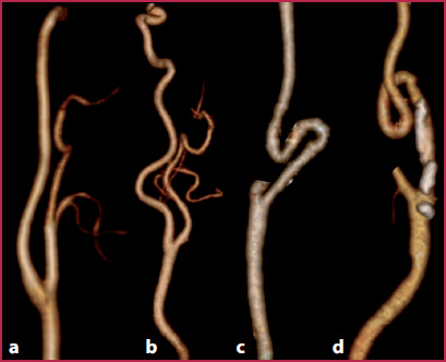
Fig. 6.4
a Common origin of the innominate artery and the left common carotid artery (bovine arch, arrow). b Bi-carotid trunk: common origin of both common carotid arteries (arrow). c The vertebral artery (in most of the cases at the left side) originates from the aortic arch (arrow). d Right-sided aortic arch with left innominate artery (arrow). e Early bifurcation of the common carotid artery (behind the clavicle, arrow). f The vertebral artery originates from the internal carotid artery (arrow)
Fig. 6.5
a Internal carotid artery with regular course. b Tortuosity: angle of the carotid artery less than 90°. c Kinking: angle of the carotid artery greater than 90°. d Coiling: 360° rotation of the carotid artery
6.2 6.2 CTA Technique
Patient Preparation
Patient supine, with the neck regularly extended and any support necessary to avoid head movements.
Peripheral venous access (at least 20 G). It is important to have a venous access at the level of the right upper limb, in order to avoid blooming artifacts during the passage of the contrast agent through the left brachiocephalic trunk (which is anatomically localized in front of the origin of the supra-aortic vessels and is very close to the innominate artery).
Remove any metallic material present in the head and neck region.
Table 6.4
CT technical parameters
4 MDCT | 16 MDCT | 64 MDCT | 128 MDCT | Dual source | |
|---|---|---|---|---|---|
kVp | 120 | 120 | 120 | 120 | 120-120 |
mAs | 200-300 | 200-300 | 180-200* | 180* | 120-180* |
Collimation | 4 × 1-2.5 | 16 × 0.4-0.75 | 64 × 0.4-0.625 | 128 × 0.6 | 64 × 0.6 × 2 |
Slice thickness (mm) | 1-3 | 0.625-1 | 0.5-1 | 0.6 | 0.6 |
Recon increment (mm) | 0.4-0.6 | 0.5-1 | 0.5 | 0.4 | 0.4 |
Table 6.5
Contrast media (cm) administration
Cm | 4 MDCT | 16 MDCT | 64 MDCT | 128 MDCT | Dual source |
|---|---|---|---|---|---|
Iodine concentration (mgl/mL) | 350-400 | 350-400 | 350-400 | 350-400 | 350-400 |
Cm volume (mL) | 90-75 | 65-55 | 60-50 | 60-50 | 60-50 |
Saline volume (mL) | 50-80 | 50-80 | 40 | 40 | 40 |
Flow rate (mL/s) | 4.0 | 4.0 | 4.0-5.0 | 4.0-5.0 | 4.0-5.0 |
Acquisition Technique
Acquire topogram on a coronal plane and place scan volume (from the head to the aortic arch).
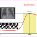
Place the region of interest (Rol) at the level of the aortic arch if a bolus tracking technique is used, and start the scan when a value of 60-80 HU is reached.
Scan the patient in the craniocaudal direction (Table 6.4).
To obtain optimal CTA imaging of the carotid arteries it is mandatory to have:
high flow rates (at least 4 mL/s) (Table 6.5);
high-concentration contrast agents;
a scan duration as short as possible, always keeping pitch values within the limits.
Because of the high speed of carotid circulation and the short transit time from the heart to the carotid and intracranial vessels, optimal CTA of the carotid arteries requires high flow rates for contrast medium injection, a small volume of the contrast agent and very quick scans (see Chapter 1), in order to avoid artifacts due to the presence of the contrast medium coming from venous structures.
6.3 6.3 MRA Technique
Patient Preparation
Patient supine, with neck regularly extended and any support necessary to avoid head movements.
Peripheral venous access (22-20 G). As with CTA, MRA also requires a venous access at the level of the right superior limb, in order to avoid artifacts during the passage of the contrast agent through the left brachiocephalic trunk (which is localized in front of the origin of the supra-aortic vessels and is very close to the innominate artery).
Remove any dentures and any other metallic material present in the head and neck region. Also remove any cosmetics or contact lens.
Use surface coils for the head and neck
Image Acquisition
ToF Sequences
Currently, 2D or 3D Time of Flight (ToF) sequences (Table 6.6) are mainly used for carotid imaging in patients with contraindications or intolerance to paramagnetic contrast agents.
Table 6.6
Technical parameters: ToF
TR (ms) | 120 |
TE (ms) | 200-300 |
Field of view (mm) | 4 × 1-2.5 |
Slice thickness (mm) | 1-3 |
Matrix (mm) | 0.4-0.6 |
The literature describes diagnostic accuracy values slightly lower than those obtained using contrast-enhanced sequences.
Acquire localizer on three planes;
Place sequence volume on a transversal plane (remember to correctly place the volume of the sequence: the direction of the flow to be visualized must be perpendicular to the plane of the sequence volume);
Place a saturation band at the top of the acquisition volume in order to suppress the signal coming from the venous vessels (cardiocentric flow).
Limits of these sequences are: the risk of overestimating severe stenosis (Fig. 6.6), resulting in incorrect diagnosis of vessel occlusion due to artifacts that suppress the signal from protons that are in transit in tortuous areas (course not perpendicular to the acquisition volume) or because of the severe caliber reduction (reduction of flow velocity); poor image quality caused by moving artifacts due to long acquisition times.
Phase Contrast Sequences
Phase contrast sequences (PC) (Table 6.7) are used less often in clinical practice because of their long acquisition times compared to other sequences. However, they may be used in the evaluation of the flow dynamics of carotid stenosis and to differentiate between near-occlusion and retrograde flow in a real occlusion, thereby allowing visualization of the flow direction.
Acquire localizer on three planes;
Place sequence volume with acquisition direction perpendicular to those of the flow to be visualized.
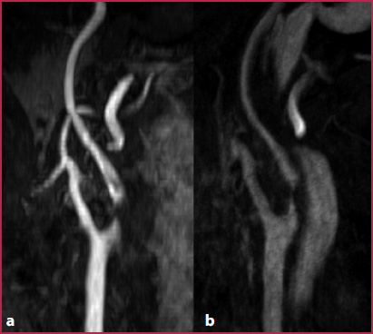
Fig. 6.6
a Using ToF sequences, a signal loss due to proton dephasing at the level of a severe stenosis may occur, leading to overestimation of the stenosis. b The use of intravascular contrast agents and the acquisition of images in the equilibrium phase enable more accurate evaluation of stenosis
Table 6.7
Technical parameters: phase-contrast
TR (ms) | ≥30 (according to R-R interval) |
TE (ms) | 6 |
Flip angle | 20° |
Slice thickness (mm) | 6 |
Matrix | 192 × 256 |
Velocity encoding (cm/s) | 120 |
Table 6.8
Technical parameters: 3D gradient-echo sequences
TR (ms) | 3,5 |
TE (ms) | 1,2 |
Flip angle | 30° |
Slice thickness (mm) | 0.7 |
Matrix (mm) | 384 × 384 |
Acquisition time (s) | 14 |
3D Gradient-Echo Sequences
The main advantages of 3D gradient–echo sequences (GRE) (Table 6.8) in imaging techniques for the carotid arteries are the high spatial resolution (with isotropic or nearisotropic voxels measuring < 1 mm3 and a matrix of at least 384 x 384), the high temporal resolution (acquisition time needs to be kept between 14 and 18 seconds), and the possibility of using subtraction techniques in order to remove the signal from extra-vascular structures (by using a pre-contrast mask) and to increase image contrast (Fig. 6.7).
Acquire localizer on three planes;
Acquire 3D-GRE sequence used as pre-contrast mask on a coronal plane (a small number of images enables acquisition times to be reduced);
Use a fluoro-triggered MR technique to visualize the arrival of the contrast agent (this technique relies on the acquisition of multiple low-spatial resolution images acquired at the level of the heart that enable real-time visualization of contrast agent arrival) (Table 6.9 shows the parameters for contrast medium injection);
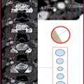
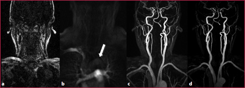
Fig. 6.7
a Pre-contrast mask acquired on a coronal plane. b Fluoro-MR acquired on a coronal plane with real-time visualization of contrast agent arrival (arrow). c 3D GRE sequence acquired after contrast agent injection. d Post-contrast 3D GRE sequence after subtraction of the mask
Table 6.9
Contrast medium