Fig. 26.1
In this view, the insertion point is 1 mm lateral to the lateral aspect of the superior articular process (SAP) and allows needles to be advanced parallel to the beam
Prior to needle placement, a skin wheal is made with lidocaine 1 % (∼1 cc) using a 25-gauge 1.5-in. needle. To anesthetize the needle track, one can use a 25-gauge 3.5-in. needle advanced under to the level of the SAP. Excessive use of local anesthetic may obscure nerve root impairment and could potentially anesthetize the sinuvertebral and ramus communicans nerves, thus altering the evoked pain response during disc stimulation and creating a false-negative response. A single- or double-needle technique may be used; however, both the North American Spine Society and the International Spinal Injection Society recommend a double-needle approach due to lower risk of disc infection (although single-needle techniques have proved adequate and safe since the use of prophylactic antibiotics) [3, 25, 32].
Puncture of L1–L5 Intervertebral Discs
In the double-needle technique, a styletted 25-gauge, 6-in. needle is placed into each disc through a 20-gauge 3.5-in. introducer needle under fluoroscopic guidance. To protect the discographer’s hand from radiation exposure, forceps may be used to grasp the introducing needle. The introducer needle is advanced parallel to the fluoroscopic beam using an oblique fluoroscope view (Fig. 26.2). If bony obstruction is encountered, the physician must confirm whether the needle has contacted the SAP or the vertebral body. If necessary, the needle may be slightly withdrawn and its trajectory modified. The introducer needle can be either advanced just over the lateral edge of the SAP or advanced to the margin of the disc. After confirming introducer needle position with a lateral view, a 25-gauge, 6-in. discogram needle is slowly advanced into the center of the disc through the introducer needle while monitoring the lateral view. A slight bend placed on the end of the discogram needle facilitates navigation. When the needle contacts the disc, position should be checked using AP and lateral views, with the ideal positioning of the needle on the line between midpoint of pedicles on AP view and posterior vertebral margin on lateral view (Fig. 26.3a, b).
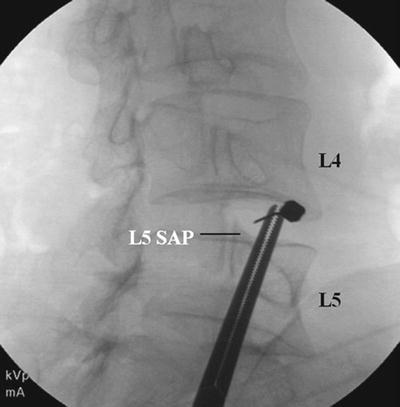
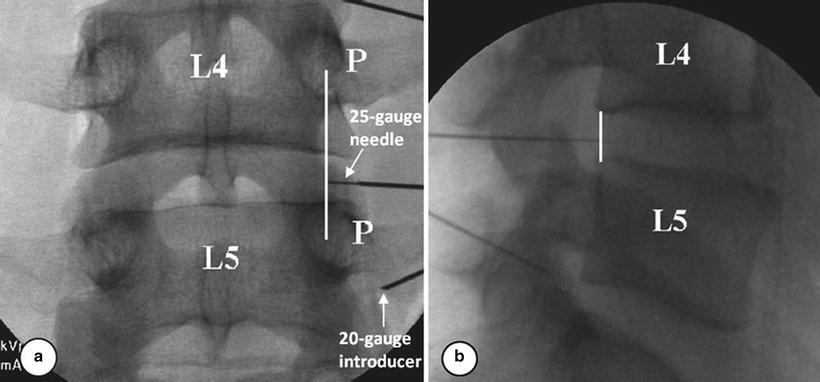
Fig. 26.2
The introducer needle is advanced parallel to the fluoroscopic beam using an oblique fluoroscope view
Fig. 26.3
(a, b) When the needle contacts the disc, position should be checked using AP and lateral views, with the ideal positioning of the needle on the line between midpoint of pedicles on AP view and posterior vertebral margin on lateral view
Contact with the annulus fibrosus is characterized by the perception of firm resistance and frequently the patient experiencing a momentary sharp or sudden aching sensation in the back or the buttock. The needle is then advanced to the center of the disc. This requires confirmation both in AP and lateral views (Fig. 26.4a, b). If the needle tip is in the midline of the disc on the AP view but anterior on the lateral view, the needle entered the disc too far laterally. If the needle tip is centered on the AP view but posterior on the lateral image, the needle entered the disc too far medially.
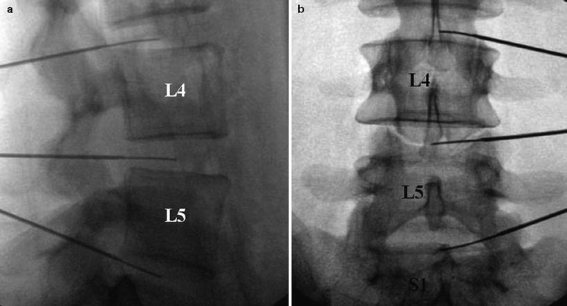
Fig. 26.4
(a, b) Contact with the annulus fibrosus is characterized by the perception of firm resistance and frequently the patient experiencing a momentary sharp or sudden aching sensation in the back or the buttock. The needle is then advanced to the center of the disc. This requires confirmation both in AP and lateral views
Puncture of L5-S1 Intervertebral Disc
Disc access at the L5-S1 interspace can be more challenging because of an overlying iliac crest and broader interfacetal distance at that level. In this case, a curved, double-needle technique is recommended. The fluoroscopy tube is rotated only far enough to bring the facet joint space approximately 25 % of the distance between the anterior and posterior vertebral margins. The introducer needle is inserted between the S1 SAP and the iliac crest (Fig. 26.5). The discography needle is advanced under direct fluoroscopic vision, while the introducer needle is simultaneously retracted slightly. This unsheathes the discography needle, which should be turned so that the curve or bend bows the introducer needle in a medial and posterior direction through the “safe triangle.” If the needle fails to track medially and posteriorly, it will not pass toward the center of the disc and may strike the ventral ramus, in which case the needle should be removed and its curvature accentuated. If the needle is blocked by the SAP, the inner needle is retracted into the introducer needle, and the pair is advanced to the lateral edge of the S1 SAP. The inner discography needle may then be directed toward the center of the disc. Ideally, the needle should be within 4–5 mm of the center on AP and lateral fluoroscopy (Fig. 26.6a, b).
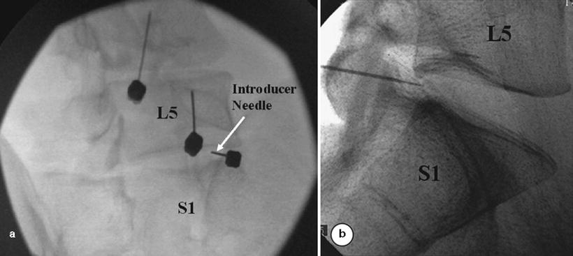
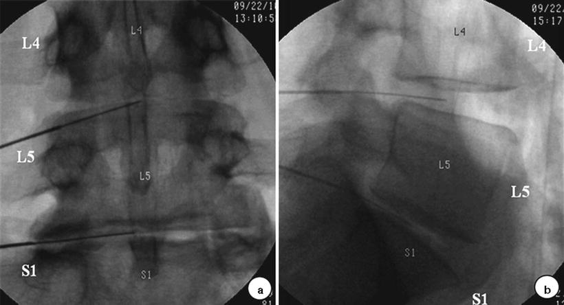
Fig. 26.5
(a, b) The fluoroscopy tube is rotated only far enough to bring the facet joint space approximately 25 % of the distance between the anterior and posterior vertebral margins. The introducer needle is inserted between the S1 SAP and the iliac crest
Fig. 26.6
(a, b) The inner needle may then be directed toward the center of the disc. Ideally, the needle should be within 4–5 mm of the center on AP and lateral fluoroscopy
Provocation Using Pressure Manometry
Provocation
Once the needle tip is in the center of nucleus pulposus, nonionic contrast medium mixed with antibiotic is injected into each disc at slow velocity, using preferably a controlled injection syringe with digital pressure readout. The disc is slowly pressurized by injecting 0.5 mL increments through a syringe attached to a pressure measuring device, while recording the opening pressure, the injection pressure, the location of contrast medium, and any pain response evoked. Injection continues until one of the following end points is reached: pain response ≥7/10, intradiscal pressure >50 psi a.o. above opening in a disc with a grade 3 annular tear or 80–100 psi a.o. with a normal-appearing nucleogram, or a total of 3.5 mL of contrast has been injected. Typical opening pressures are 5–25 psi a.o., depending on the degree of nuclear degeneration; if it exceeds 30 psi a.o., this usually indicates that the needle tip is lodged within the inner annulus and needs to be repositioned.
Imaging
AP and lateral images of all injected discs are saved as part of the permanent record. A variety of fluoroscopic patterns may occur in abnormal discs: cotton ball, lobular, irregular, fissured, and ruptured (Fig. 26.7a) [33]. The appearance of the normal nucleus following the injection of contrast medium is classic: the contrast medium assumes either a lobular pattern or a bilobed “hamburger” pattern (Fig. 26.7b). Contrast medium may extend into radial fissures of various lengths but remain contained within the disc (Figs. 26.7 and 26.8). Contrast may escape into the epidural spaces through a torn annulus or through a defect in the vertebral end plate [34]. In other cases, the disc can look completely fissured and disrupted. However, none of these patterns alone are indicative of whether the disc is painful; that can be ascertained only by the patient’s subjective response to disc injection.
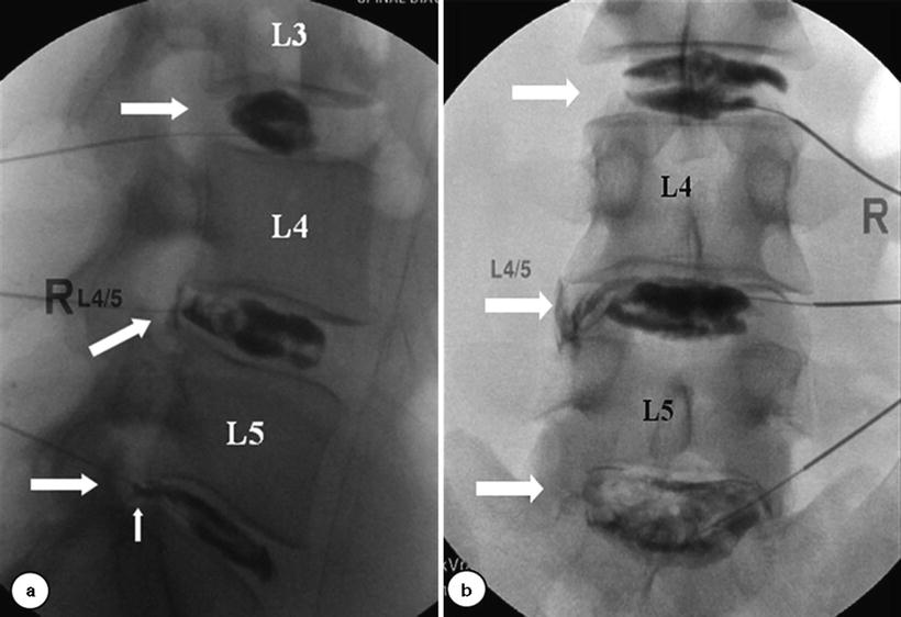
Fig. 26.7
(a) A variety of fluoroscopic patterns may occur in abnormal discs: cotton ball, lobular, irregular, fissured, and ruptured. (b) The appearance of the normal nucleus following the injection of contrast medium is classic: the contrast medium assumes a either a lobular pattern or a bilobed “hamburger” pattern
Fig. 26.8
Contrast medium may extend into radial fissures of various degrees
Post-discography axial CT scanning provides the most accurate depiction of internal disc architecture. The location of degeneration is described by dividing the disc into four quadrants [17]. If the contrast is confined to the nucleus, then no quadrant disruption is present; if the contrast is dispersed, then its location is described (e.g., single quadrant disruption, right posterior; two-quadrant disruption, left anterolateral and right posterior, etc.). The degree of radial and annular disruption is most commonly described [17, 35] using the modified Dallas discogram scale (Fig. 26.9) [32, 35–37]. Grade 0 describes contrast contained within the nucleus; grades 1–3 describe degree of fissuring extending to the inner, middle, and outer annulus, respectively; grade 4 describes a grade 3 annular fissure with a greater than 30° circumferential arc of contrast. A grade 5 annular tear indicates rupture or spread of contrast beyond the outer annulus (Fig. 26.8).
Interpretation
Discography is a provocational test which attempts to mimic physiologic disc loads and evoke the patient’s pain by increasing intradiscal pressure with an injection of contrast medium. Increased intradiscal pressure is thought to stimulate annular nerve endings, sensitized nociceptors, and/or pathologically innervated annular fissures. The intensity of the provocation stimulus must be carefully controlled through the skilled operation of a manometer syringe or an automated manometer, permitting more precise comparisons between patient discs and between discographers. Most abnormal discs will be painful between 15 and 50 psi a.o. [38] and are termed “mechanically sensitive” based on a four-type classification introduced in the 1990s by Derby et al. in respect to annular sensitivity [39]. Discs which are painful at pressures <15 psi a.o. are termed low-pressure positive or “chemically sensitive” discs [39]; if discs are painful between 15 and 50 psi a.o., they are termed “mechanically sensitive” discs. Indeterminate discs are painful between 51 and 90 psi a.o., and normal discs are not painful on provocation. An operator using manual “thumb” disc pressurization to 100 psi a.o. reported to have higher false-positive rate in asymptomatic subjects than other operators [24, 40]. If a disc is painful at >50 psi a.o., the response must be reported as indeterminate, because it is difficult to distinguish between a pathologically painful disc and the pain evoked from simply mechanically stimulating a normal or subclinically symptomatic disc. To limit false-positive responses, the most up-to-date discography standards are set at a pressure criteria of <50 psi a.o. to define a positive response [32, 41].
Injection speed is also a confounding factor and may account for inter-operator variability in results and increased false-positive responses. At high injection speeds, the true intradiscal pressure (dynamic pressure) is higher than the recorded static pressure [42]. The dynamic pressure, measured only in research settings, is the actual pressure which would be recorded with an intradiscal pressure sensor. Currently, the pressure is measured indirectly via a manometric syringe which records plateau static pressures, postinjection. The pain during activities of daily living is more closely correlated to dynamic peak pressure [39]. Static pressure is reflective of dynamic pressure when recorded by needle sensor and manometer only at slower injection speeds (<0.08 mL/s) [42].
Pain assessment during the disc provocation is the most important information obtained from discography. If the patient’s pain intensity, location, and character are similar to or the same as the patient’s clinical symptoms, the criteria for concordant pain are satisfied. A true positive pain response is ≥7/10, sustained for greater than 30–60 s; true discogenic pain is less likely to decrease rapidly. Pain which resolves within 10 s should be discounted. It is recommended to confirm all positive responses with manual repressurization with a small volume. If repressurization does not provoke concordant ≥7/10 pain at <50 psi a.o., then the response is considered indeterminate. Clinically, patients with discogenic pain tend to have increased pain postoperatively and an exacerbation of symptoms lasting 2–7 days.
Technique of Cervical Discography
Patient Position
The patient is placed supine on the fluoroscopy table with a cushion placed under his or her shoulders to slightly hyperextend the neck, which may help to improve a disc access. While the side to be punctured in lumbar discography is that opposite the patient’s dominant pain, a right-sided approach is used for cervical discography because the esophagus lies to the left in the lower neck. The patient’s neck is prepared and draped in a sterile fashion.
Disc Puncture
Midline Approach
The disc level to be studied is identified on the AP view of fluoroscopy. The tube is rotated in a cephalad-caudal direction to bring the end plates parallel to the beam. Pressure is applied with the index finger to the space between the trachea and the medial boarder of the sternocleidomastoid muscle (Fig. 26.10). Firm but gentle pressure will displace the great vessels laterally and the laryngeal structures and trachea medially. Below C4, the right common carotid artery and the internal carotid artery above C4 are palpated. The fingers are insinuated until they encounter the anterior surface of the vertebral column. Since the carotid artery is manually displaced to allow safe needle passage into the disc, and the carotid body may be compressed, administration of IV atropine is therefore suggested to minimize the possibility of vasovagal response [43, 44]. The needle entry point should be medial to the medial border of the sternocleidomastoid muscle, thus avoiding the pharynx superiorly and the apex of the lungs inferiorly. A shorter 25-gauge 2.5-in. needle is recommended for easier and safer handling. With the point of the needle just medial to or under the index finger, both the needle and the index finger can be moved in unison. The trachea is pushed medially by the fingernail of the index finger, and when the needle overlies the disc at 20–40° angle, the needle is introduced through the skin directed toward the anterior lateral aspect of the disc (Fig. 26.11). Once the needle is passed several millimeters into the disc, the lateral view is recommended to guide further advancement, taking precaution to not pass the needle through the disc and into the epidural space or spinal cord (Fig. 26.12). In order to gauge the depth of penetration, the needle may be directed to and touch the anterior disc body just above or below the disc margin before the insertion into the center of the disc.
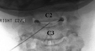
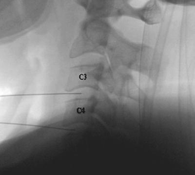
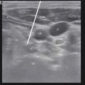
Fig. 26.10
Pressure is applied with the index finger to the space between the trachea and the medial boarder of the sternocleidomastoid
Fig. 26.11
The trachea is pushed medially by the fingernail of the index finger, and when the needle overlies the disc at 20–40° angle, the needle is introduced through the skin directed toward the anterior lateral aspect of the disc
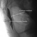
Fig. 26.12
Once the needle is passed several millimeters into the disc, the lateral view is used to guide further advancement, taking precaution to not pass the needle through the disc and into the epidural space or spinal cord
Lateral Approach
In this approach, after aligning the vertebral end plates of the target level, the fluoroscopic beam is axially rotated until the anterior margin of the uncinate process is moved approximately one-quarter of the distance between the anterior and posterior lateral vertebral margins. In this view, the target insertion point is 1–2 mm medial to the anterior margin of the uncinate process (Fig. 26.13). The skin entry point will be over the lateral neck muscles and posterior to the great vessels or trachea. Pressure displacement of the great vessels is difficult and usually not done. This region is highly vascular, and patients have to be observed for signs of hematoma. Before and during the injection of contrast, the needle position within the center of a disc and a spread of contrast material inside the disc have to be confirmed with both AP and lateral fluoroscopic images (Fig. 26.14a, b). At C7-T1, the medial approach is preferred to avoid puncturing the apex of the lung.
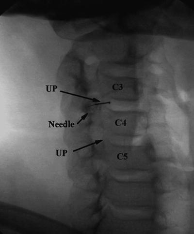
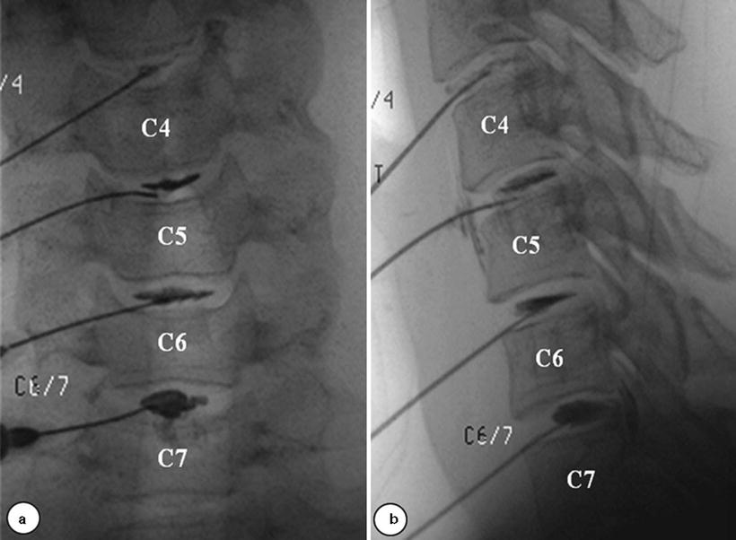
Fig. 26.13
In this approach, after aligning the vertebral end plates of the target level, the fluoroscopic beam is axially rotated until the anterior margin of the uncinate process (UP) is moved approximately one quarter of the distance between the anterior and posterior lateral vertebral margins. In this view, the target insertion point is 1–2 mm medial to the anterior margin of the uncinate process (UP)
Fig. 26.14
(a, b) Before and during the injection of contrast, the needle position within the center of a disc and a spread of contrast material inside the disc have to be confirmed with both AP and lateral fluoroscopic images
Provocation and Interpretation
The clinical utility of provocative discography for solving puzzling presentations of atypical pain resulting from cervical discogenic lesions has been demonstrated. In a systematic review of the literature, Manchikanti showed a significant role for cervical discography in selecting surgical candidates and improving surgical outcomes, when strict criteria requiring a concordantly painful disc and two negative controlled discs, one above and one below the affected level, are utilized [45]. Normal cervical discs hold only 0.25–0.5 mL of fluid, and intradiscal injection of normal discs should not be painful. Schell et al. demonstrated an average pain response during disc stimulation in asymptomatic subjects as 2.2/10, whereas it was 5.2/10 in patients with neck pain. He showed that MRI cannot reliably identify the sources of neck pain and provocative discography results had better correlation between cervical discogenic pain and annular disc disruption compared to MRI [46, 47]. A 1–3-mL syringe with contrast media is attached to the needle. Manual syringe pressure is increased slowly until the intrinsic disc pressure is exceeded. Concordancy and pain intensity are recorded at 0.2 mL increments. A positive response requires provocation of significant (>6–7/10) concordant pain during a confirmatory repeat injection of another 0.1–0.2 mL of contrast. Without an asymptomatic “control” disc, there is no evidence that the patient can discriminate between symptomatic and asymptomatic discs, especially in case of multiple concordant pain levels. It is observed that pressurization of the cervical discs will often cause separation of the end plates, and this movement may cause pain secondary to a symptomatic z-joint. It is recommended to rule out z-joint pain following an analgesic block protocol before performing cervical discography [48].
Technique of Thoracic Discography
Patient Positioning
The patient lies prone on the fluoroscopy table. Skin is prepared and draped in a sterile fashion. As a rule, the side to be punctured is that opposite the patient’s dominant pain.
Related posts:
 Transforaminal Epidural Steroid Injections
 Stellate Ganglion Blockade
 Clinical Applications of Neuromodulation: Section on Angina and Peripheral Vascular Disease
 Superior Hypogastric Plexus, Ganglion Impar Blocks, and Neurolysis
 Complications of Interventional Pain Management Techniques
 Spinal Cord Stimulation
Stay updated, free articles. Join our Telegram channel

Full access? Get Clinical Tree


