Chapter 3 Radiation detection and measurement
Introduction
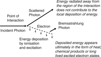
Chapter 2 described the various processes by which photons interact with matter. These interactions produce charged particles (electrons and possibly positrons) which then travel through matter, losing energy by collision processes (ionization and excitation of atoms) and through radiative processes (production of bremsstrahlung), as illustrated in Figure 3.1.
1. transfer of energy from the radiation to emitted charged particles
2. deposition of energy by the emitted charged particles through collision processes.
The first stage is governed by the interaction coefficients for photons in matter as discussed in Chapter 2. The second stage is dependent upon the energies of the emitted charged particles and their subsequent patterns of energy deposition as determined by their stopping powers. Together, these determine the differences in deposition of energy for differing photon energies and materials. For charged particle beams only the second stage is relevant.
Kerma
where  Etr represents the energy transferred from photons to charged particles and is the sum of initial kinetic energies of all the charged particles liberated by uncharged ionizing radiation from an amount of material of mass
  m.
m.
It may be seen from Figure 3.1 that for the Compton interaction illustrated:
1. the energy of an incident photon is shared between a scattered photon and the ejected electron. The scattered photon carries its energy away from the immediate region of the interaction. The term terma represents the total energy removed from the beam per unit mass of matter, including that given to the charged particles and that scattered as photons. Terma is therefore always greater than kerma
2. the electron travels through matter losing energy continually until its kinetic energy is exhausted
3. the travelling electron may lose some energy by bremsstrahlung, producing photons which, like the scattered photon, carry energy away from the immediate vicinity. The term collision kerma refers to that proportion of kerma that is deposited via collision processes only. Kerma and collision kerma differ only in accounting for the energy that is re-radiated. In body tissues, the energy re-radiated is small, being less than 1%, so these two quantities are almost equal.
Absorbed dose
The travelling electrons deposit energy in matter through which they pass, and so the energy deposited by these electrons is displaced in distance from the site of initial transfer of energy from the photon beam. The amount of energy deposited in a small mass of the material is termed the absorbed dose, which is defined by ICRU [1] as:
where  Ed is the total energy deposited by these charged particles in a volume element of mass
  m.
m.
1. the distance travelled by secondary charged particles is sufficiently small for it to be neglected, such that energy may be considered to be absorbed by the matter at the point where it is transferred from photons to the charged particles – a condition known as point deposition of dose. This occurs for low energy photons, where the emitted electrons can travel only short distances, as detailed in Chapter 2
2. the energy lost from the region of initial transfer by the movement of charged particles away from that region is exactly compensated for by energy brought into the region by other travelling electrons produced elsewhere – a condition known as energy equilibrium, or more generally as charged particle equilibrium.
Measurement and standardization of dose
Dose standards
The UK national standard instruments for the standardization of absorbed dose are of two types:
1. calorimeters for megavoltage photon and electron beams. Calorimeters are used to provide direct determination of absorbed dose [2]
2. free-air ionization chambers for lower energy photon beams from x-ray generators operating at up to 300 kV [3, 4]. These provide direct determination of air kerma from which the absorbed dose to water can be calculated.
Traceability of measurement
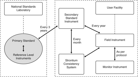
In order to ensure consistency of dose measurement between centre, it is necessary for measurements to be traceable back to the appropriate national standard. This is achieved through a hierarchical arrangement shown schematically in Figure 3.2. Dose measuring instruments within individual hospitals (the field instruments) are used to measure the radiation beams of radiotherapy treatment units. These are calibrated periodically (i.e. annually in the UK) against a secondary standard instrument. The secondary standard instruments are reserved solely for this purpose and are not used to make routine beam measurements. Guidelines on the choice of dosimeter systems for use as secondary standard instruments have been produced by IPEM [5]. Each secondary standard instrument is calibrated periodically (i.e. every 3 years in the UK) by the Standards Laboratory by comparing the response against national reference level instruments that are in turn compared annually with the national standard instrument. The national standards are themselves compared at intervals with equivalent standard instruments developed by standards laboratories in other countries.
• the basis for the standard dose measurement
• the instrumentation and methods for transfer of dose to field instruments by a series of intercomparisons, including specification of any equipment used and any conditions that must exist for the intercomparison to be reliable
• instructions for use of the calibrated dosimeter in routine practice.
Standard calorimeter
where C is the specific heat of the irradiated matter (the amount of energy needed to raise the temperature of unit mass of a substance through 1 degree, expressed in units of in J.kg−1.°C−1) and δT is the change in temperature in degrees Celsius. The equation above assumes no loss of heat to the surrounding environment or structures. Note that the specific heat may also be expressed in calories rather than joules, in which case an additional numerical multiplier of 4.18 is necessary in the above equation.
The national standard calorimeter is based on the irradiation of a known mass of graphite (the core of the NPL high energy photon calorimeter measures approximately 20 mm diameter by 3 mm thick) within a graphite phantom. The design of the calorimeter, a photograph and schematic drawing of which are shown in Figure 3.3, has the core shielded by three jackets, each separated by vacuum in order to minimize heat loss. Temperature measurements are carried out using thermistors embedded in the graphite core, the resistances of which change with temperature. In practice, since the amount of heat energy lost from the core to surrounding structures is not negligible and may be difficult to determine, the rise in temperature resulting from irradiation is compared with the rise in temperature produced by heating the core using a known amount of electrical energy, allowing absorbed dose to be determined directly instead of using the above equation.
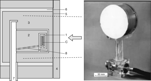
Figure 3.3 Photograph and simplified schematic drawing (redrawn from [2]) of the national standard high energy photon calorimeter, showing the graphite core (C) surrounded by three insulating graphite jackets (1, 2 &. 3). The entire device is housed within a Perspex evacuation vessel (6) which has a thin aluminized mylar front window (5) and which is evacuated via a port (7). A plate (4) suitable for the energy to be measured can be added to the front face. Electrical connections to the core pass through the device (8).
Graphite has the advantage of having no chemical defect (i.e. all the absorbed energy appears as heat) and a specific heat that is one-fifth that of soft tissue or water, thereby producing greater changes in temperature per unit dose. The absorbed dose to water may be calculated from the absorbed dose to graphite using the correction factors determined by Nutbrown [6].
As the standard calorimeter cannot be used in a water tank, a number of specially constructed ionization chambers termed ‘reference standard instruments’ are calibrated annually against the graphite calorimeter in a common graphite phantom. These reference instruments are then used to calibrate in turn the secondary standard instruments using a water phantom. The calibration factor provided for each secondary standard instrument is specific to a stated beam quality and depth of measurement, the latter being important as the spectral content of a radiation beam changes with depth. Table 3.1 shows those photon beam qualities at which calibration factors based on absorbed dose to water as determined by the standard graphite calorimeter are provided by the National Physical Laboratory, UK [7, 8]. When used as a basis for calibration in a radiation beam in the user’s department, the beam quality for that beam must be determined and the appropriate calibration factor obtained by interpolating from the results provided by the standards laboratory. Calibrations in megavoltage photon beams are carried out at the depths shown in Table 3.1 which are beyond the range of contaminating electrons in the radiation beam that have been ejected from the head of the treatment machine [9].
Table 3.1 Photon beam qualities used for therapy level absorbed dose to water calibrations
| Beam quality (TPR20/10) | Equivalent beam energy | Reference depth (cm) |
|---|---|---|
| 0.568 | 60 Co | 5 |
| 0.621 | 4 MV | 5 |
| 0.670 | 6 MV | 5 |
| 0.717 | 8 MV | 5 |
| 0.746 | 10 MV | 5 |
| 0.758 | 12 MV | 7 |
| 0.779 | 16 MV | 7 |
| 0.790 | 19 MV | 7 |
The quantity TPR20/10 is the ratio of tissue-phantom ratios at depths of 20 cm and 10 cm respectively, used by Standards Laboratories as the specifier of beam quality (see Chapter 2).
A number of Standards Laboratories have developed water calorimeters that directly measure the rise in temperature of a known mass of water. These avoid uncertainties with the national standard instrument in moving from a graphite phantom to a water phantom. Such instruments have been used to confirm doses specified using other systems of dosimetry for photon and charged particle beams and are being increasingly developed as national dosimetry standards [44–48]
The free air chamber
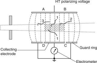
The free air chamber is the primary standard instrument for kV beams, and is shown schematically in Figure 3.4. The free air chamber effectively determines the energy transferred to secondary electrons as a result of interactions of a photon beam within a defined mass of air, i.e. air kerma (ka).
Figure 3.4 shows the physical arrangement. The metal plate that forms the electrode which carries the high tension (HT) polarizing voltage runs the full length of the chamber, whereas the other plate has the collector electrode as the central part only, separated and electrically isolated from adjacent metal plates called guard rings, which are held at the same electrical potential as the collector electrode. This arrangement ensures that the electric field within the region of the collector electrode is uniform and perpendicular to that electrode. Any ions produced in air within the region ABCD on the diagram will be collected on the collector electrode, whereas any ions produced outside this region will be collected on the guard rings and will not be included in the measurement.
Charged particle equilibrium
The shaded region in Figure 3.4 indicates the volume of air of interest irradiated by the photon beam, being specified by the cross-sectional area of the photon beam and the length of the collector electrode. The mass of air within this volume depends upon atmospheric conditions (temperature and pressure). Correction for different atmospheric conditions is covered in a later section.
Practical ionization chambers
One such instrument is the ionization chamber.
Bragg-Gray cavity theory
where Ja is the ionization produced per unit mass of air, W is the average energy lost by the electrons per ion pair formed in the air. If the air is now to be replaced by medium, the energy per unit mass imparted to the medium (Dm) would equal the absorbed dose to air multiplied by the electron mass stopping power for the medium divided by that for air (S/ρ)ma (averaged over the energy spectrum of the electrons), i.e.:
where (μ/ρ)mw is the ratio of mass absorption coefficient for the medium divided by that for the chamber wall.
Dose determination based on calibrated instruments
where D is the dose, R is the mean corrected reading and ND is the absorbed dose calibration factor.
Requirements for practical ionization chambers
Secondary standard instruments are constructed to less stringent standards, but are required to operate over a range of beam energies and to remain consistent in response between recalibrations by the Standards Laboratories (i.e. 3 years). They must be fully transportable so that they can be used to transfer calibrations to other instruments in beams from different treatment machines, or even across different hospital sites. These chambers maintain an accuracy of calibration around 1%. Guidelines covering secondary standards instruments have been published [5].
Field instruments are used in daily measurements within hospitals. Different types of instrument exist, depending upon the nature of those measurements. Thimble chambers, described in detail in the following section, are generally used for calibration of megavoltage photon beams. Chambers based upon the design of the Farmer chamber [10] feature an air cavity of about 0.6 ml, providing a reasonable balance between the response to radiation and smallness of size, are adequate for measurements in relatively uniform radiation beams with an accuracy of 1–2%. Chambers which have much smaller internal dimensions are used to measure variations in dose distributions, which can be very rapid at beam edges. Here, chambers of 0.1 ml or less may be used, with a trade-off between accuracy of response and spatial resolution. Where there is a rapid variation in dose deposited with depth, such as for measurements in the build-up region of photon beams or in the fall-off region of electron beams, parallel plate chambers are used to ensure good depth resolution for the measurements.
Thimble ionization chamber
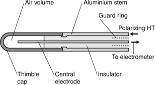
A thimble chamber is an ionization chamber that has a central electrode (the collector electrode) in a volume of air that is contained by a thimble-shaped cap which forms the HT electrode which fits closely onto a metallic stem. The central electrode passes through the inside of the stem and is insulated from the metallic stem by a suitable high-quality insulator material such as amber or polythene. This is schematically shown in Figure 3.5. The cap is generally made of a low atomic number low-density material such as graphite, although various plastic materials have been used where the plastic has been manufactured to be conductive (e.g. Shonka plastic: [11]) or has been coated with graphite to be conductive. The central electrode may be made of aluminium or conductive plastic.
Stay updated, free articles. Join our Telegram channel

Full access? Get Clinical Tree


