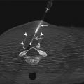
Fig. 3.1
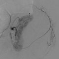
Distribution of dose within a patient undergoing an angiographic procedure using a PA projection
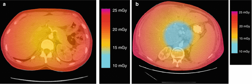
Fig. 3.2
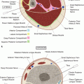
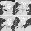
Distribution of dose within a patient undergoing a CT procedure. (a) Small patient, (b) large patient
During CT-guided interventions, the entrance air kerma rate (EAKR) is approximately equal to the CTDI100 1 rate for a typical patient [1]. However, manufacturers typically display the CTDIvol rate or accumulated CTDIvol, not CTDI100, on the scanner. Based on the relationship between CTDI100 and CTDIvol, the EAKR for a typical patient is equal to approximately 0.6 × CTDIvol [2]. Typical entrance air kerma rates during CT-guided interventions range from 1.5 to 8 mGy/s, depending on the operating mode and scanner hardware. If we consider an EAKR of 5 mGy/s, 400 s of imaging would be required to reach an ESAK of 2,000 mGy (2 Gy). While the ESAK is not equal to the actual skin dose, it is a reasonable quantity to use for monitoring the progress of a procedure. Also, the ratio of the EAKR to the CTDI rate will vary with patient size and beam width [1]. Tables 3.1 and 3.2 provide some helpful information regarding radiation dose to the patient during CT-guided interventions.
Table 3.1
Variations in ESAK rate in CT with changes in kVp and mA
kVp | Adjustment factor | |
|---|---|---|
80 | 0.4 | ESAK changes linearly with mA. Doubling the mA doubles ESAK, halving the mA halves the ESAK for the same time |
100 | 0.7 | |
120 | 1.0 | |
140 | 1.4 |
Table 3.2
CT fluoroscopy time required to reach specific skin dose levels
Time to reach threshold (s) | |||
|---|---|---|---|
kVp | mA | 1,000 mGy | 2,000 mGy |
80 | 75 | 435 | 869 |
80 | 100 | 328 | 656 |
80 | 150 | 195 | 392 |
120 | 50 | 184 | 357 |
120 | 100 | 86 | 173 |
Operator Dose in CT-Guided Interventions
Operators face unique radiation protection challenges when working with CT. In angiography, exposure to intense backscattered radiation can be avoided by maintaining the x-ray tube beneath the patient table or by standing by the image receptor end of the C-arm when using oblique or lateral projections. In CT, some exposure to backscattered radiation is unavoidable, as the x-ray tube is not stationary but instead rotates around the patient. In addition, the intensity of stray radiation in CT is higher by approximately a factor of 10 compared to the angiography lab.
Protection of the Patient
Interventional CT procedures utilize a different workflow from diagnostic CT procedures. A typical procedure involves the acquisition of high-quality planning data, followed by the biopsy procedure and its associated scans, and often ends with the acquisition of another set of high-quality post-procedure data. The technical factors used during the different phases of the procedure should be tailored to the goals of each individual phase. In particular, the biopsy portion of the procedure should use lower techniques than the pre- and post-procedure scans. This is especially important considering the fact that the patient is likely to be scanned multiple times at the same location. The use of excessive technical factors for the biopsy phase may put the patient at risk for deterministic radiation injuries such as erythema or epilation [4]. High-contrast anatomical landmarks can be used to navigate on the biopsy scans, or an external electromagnetic guidance system can be used in conjunction with the planning data to guide the intervention.
Appropriate Technical Factors for CT-Guided Interventions
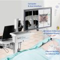
The key to maintaining appropriate patient doses during CT-guided interventions is the selection of appropriate technical factors. A CT-guided intervention is not a diagnostic imaging procedure. While high-quality pre-procedure planning data and post-procedure assessment data may be needed, the CT guidance for the actual procedure can in most cases be performed with greatly reduced technical factors (Table 3.3) [5]. Externally placed markers and internal landmarks can be used for navigation. In addition, some modern ultrasound systems offer navigation options that fuse the ultrasound images with prior CT images, and several companies manufacture guidance systems that use prior CT images for navigation.
Table 3.3
Typical technical factors for CT examinations
Procedure | kVp | mAs | CTDIvol a(mGy) | Scanlength (cm) | Number of scansin same location | Effectivedose (mSv) |
|---|---|---|---|---|---|---|
Diagnostic abdomen CT | 120 | 200 | 15 | 40 | One
Stay updated, free articles. Join our Telegram channel
Full access? Get Clinical Tree
 Get Clinical Tree app for offline access

|
